Skyleader Aircraft Skyleader

Skyleader 200 UL

The all metal trapezoidal wing with two spar construction consists of the outer parts and the wing center section. The short wing center section is firmly placed into the fuselage. The outer parts of the wing are separable for transport.

Wing profile is GA (W) – 1 at the root and the GA (W) – 2 at the tip. The main wing spar is placed in 33 % of the profile depth and is perpendicular to the longitudinal aircraft axis. The main spar is created from the dural beams and web. The beams are from metallurgical L – profiles, milled spanwise and riveted with web using full rivets. The web with changing thickness is relieved by the lightening holes spanwise. The ribs are stamped including lightening holes. The back spar is created by the L-profile and riveted web, which is relieving with lightening holes too. The cover is riveted with the pop rivets to the beams and the ribs. The flaps hinges are from dural sheets with milled grooves for flaps extending. Three safe attachment points attach the wing outer section parts with the wing center section.

The flaps – Fowler type with a proportional depth 29 % have 10 deg and 35 deg deflections. The flaps drive is mechanical in standard. The electrical system is available as an option. The mechanical drive system is created by toothed wheels with racks. The flap controller is placed in tunnel of the cockpit. Left and right parts of the flap drive are connected together. Flap construction is created by spar, ribs and cover, which are riveted with pop rivets.

The aileron is all metal with one spar. Construction consists of control rods and bent levers in the transverse control. The aileron deflections are differentiated.

The wing center section composed with two spars similar to the outer wing ones. These spars are firm attached into the fuselage construction. There are two fuel integral tanks in the front part of the wing center section, each one with 8.5 gallons of fuel capacity. The main landing gear is attached to the wing center section, so it creates an independent set, which can be moved at manufacturing or emergency transported during operation.

The all metal fuselage construction is created by dural L – form stringers, by metallic bulkheads and by cover. The stringers are attached together through the whole length of the fuselage and create a base supporting system of the fuselage. A transverse cross-section of the fuselage is shaped so that the cover could be unrolled and so was stabilized for an increasing of a critical tension. In the cockpit area is the supporting system replenished by steely spar of the closed square cross-section – middle panel of the cockpit. The seats are lengthwise adjustable and equipped by 4 points seat belts. The canopy creates perspex, which is inset into fiberglass frame with reinforcement from carbon and cevlar fibers. The canopy allows a perfect view backwards. The control is dual with control sticks and pedals. The directional control is funicular with turnbuckles.

The landing gear is retractable, controlled by electric motor with manual emergency control. Fixed Landing gear is determined for the Light Sport.

Both wheels of main landing gear and the nose wheel are towed and they are sprung with rubber shock absorbers, created by circular rubber segments. The nose landing gear is at protuberant position connecting with the foot’s control and is controllable at +15° range. The main landing gear wheels are braked with a central manual hydraulic brake lever at the control stick.

Skyleader 500 LSA

The airplane is equipped with Rotax 912 UL (80hp) engine, optionally with Rotax 912 ULS (100hp) or Rotax 914 UL (115hp turbo) engine. The engine is attached by welded bed with the use of rubber shock absorbers through the firewall into the fuselage stringers and central tunnel. Three (3) blade on-ground adjustable propeller is delivered with the plane as standard. As the optional order can be airplane equipped with mechanically or electrically in-flight adjustable propeller, two or three blade.

All metal tail units are standard alignment with a rudder and an elevator. The profile of Vertical Stabilizator and Horizontal Stabilizator is symmetrical to NACA 0012. They are created by spars, ribs and cover. An elevator is divided; therefore it is possible to take it down without disconnecting the controls. The same construction is used at the others control surfaces. A stabilizer is attached to the fuselage by four hinges and is possible to dismantle it without disconnecting the controls.

The aircraft has two integral tanks with capacity of 2×32 liters (total 64l) of the fuel. Optionally can be installed the additional fuel tanks supplying the aircraft with additional 2×15 liters (total 30 liters) of the fuel. Therefore max. amount of the fuel should rise up to 94 liters. The tanks are created by lead box inside the wing center section, out of the fuselage. They are riveted through caulk mastic and the wing center section cover forms concurrently a tank wall. The fuel delivery is ensured by a pneumatic pump for the overflowing the system and in the reason of an error or delivery deficient of the pneumatic pump is possible to use an additional electric pump. A fuel amount is indicated by two analogue fuel gauges.

The aircraft is in UL category furnished with standard instruments for flight and engine control. The Radio, Transponder, Glass Panel, GPS or another flight and engine instruments are installed on the customer’s request. Color painting, upholstery and internal cockpit surface adjustment of the aircraft is realized individually on basis of plentiful amount of offered services and products.
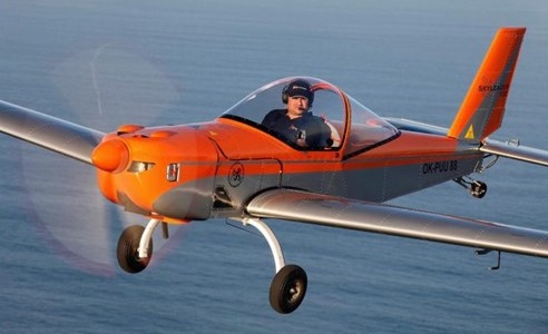
Gallery

Skyleader 100
Engine: HKS 700E
MTOW: 315kg
Cruise at 75% pwr: 75kts
Seats: 1

Skyleader 150 UL
Stall: 26 kt / 30 mph / 48 kmh
Cruise: 119 kt / 137 mph / 220 kmh
VNE: 130 kt / 149 mph / 240 kmh
Empty Weight: 282 kg / 622 lbs
MTOW Weight: 450 kg / 992 lbs

Skyleader 200 UL
Stall: 26 kt / 30 mph / 48 kmh
Cruise: 119 kt / 137 mph / 220 kmh
VNE: 130 kt / 149 mph / 240 kmh
Empty Weight: 282 kg / 622 lbs
MTOW Weight: 450 kg / 992 lbs

Skyleader 500 LSA
Stall: 31 kt / 36 mph / 58 kmh
Cruise: 120 kt / 138 mph / 222 kmh
VNE: 129 kt / 149 mph / 240 kmh
Empty Weight: 313 kg / 690 lbs
MTOW Weight: 580 kg / 1278 lbs

Skylark Aircraft Skycraft

Skycraft 446 NX25607

1946 aviation periodicals told of a “new twin-boom Skylark project” in three versions: two-place 246, four-place 446, and five–place 546. When the prototype appeared, it was as 447, with model number amended to fit the year.

The 1946 two-place Skycraft 246 featured wing ailerons and flaps. It is unknown if any were built in this designation, possibly was an evolutionary project, prised at $3,800-4,200.

No record of production found for the 1945 four-place Skycraft 445 and Skycraft 545. Partially-retracting gear to prevent structural damage in the event of a wheels-up landing, the 545 was noted in a brochure as slated for “Air Taxi service.”

Skycraft Rendering of unspecified model (company brochure)

The 1947 four-place Skycraft 446 and 447 featured all-metal construction, twin booms and tails; no ailerons, but wing spoilers served that purpose.

Partially-retracting gear to prevent structural damage in the event of a wheels-up landing. Priced at $5,800-7,500, one was built, NX25607 (registration also belonged to a North American NA-50A that went to Thailand).

Skycraft 246
Engine: 115hp Continental
Wingspan: 36’0″
Length: 26’3″
Useful load: 710 lb
Max speed: 139 mph
Cruise: 120 mph
Stall: 43 mph
Range: 445 ni
Ceiling: 12,500 ft
Seats: 2

Skycraft 445
Seats: 4

Skycraft 545
Seats: 4

Skycraft 446
Engine: 190hp Lycoming R-680
Wingspan: 36’0″
Length: 26’3″
Useful load: 1240 lb
Max speed: 162 mph
Cruise: 142 mph
Stall: 49 mph
Range: 715 mi
Ceiling: 16,000 ft
Seats: 4

Skycraft 447
Engine: 190hp Lycoming R-680
Wingspan: 36’0″
Length: 26’3″
Useful load: 1240 lb
Max speed: 162 mph
Cruise: 142 mph
Stall: 49 mph
Range: 715 mi
Ceiling: 16,000 ft
Seats: 4

Skyhook Sailwings Orion

Single seat single engined high wing mono¬plane with two axis control. Wing has swept back leading and trailing edges, and tapering chord; no tail, canard wing. Pitch control by fully flying canard; yaw/roll control by angled ¬pivot tip rudders; control inputs through stick for pitch and yaw/roll. Wing braced from above by kingpost and cables, from below by cables; wing profile Clark Y derived; 100% double surface. Undercarriage has three wheels in tricycle formation; no suspension on nosewheel and suspension (type to be decided) on main wheels. Push right go right nose¬wheel steering independent from yaw control. Brakes on main wheels.

Aluminium tube and fabric fuselage, totally enclosed. Engine mounted below wing driving pusher propeller. Windscreen made from rigid plastic sheet, side windows from Mylar film. Bainbridge Dacron used for flying surfaces.

Designer Len Gabriels has aimed to create a machine which will appeal to hang gliding and sailplane enthusiasts as well as microlighters, and in its initial form the machine is unpowered.

As first shown at the British Hang Gliding Association’s annual general meeting in March 1983, the Orion is a fully enclosed hang glider/sailplane with pitch control by weight shift moving a fully flying canard. Combined roll and yaw control is provided by tip rudders mounted under the ends of the wing and with their pivots angled at 45O to the vertical, so that they provide roll at the same time as yaw. Both may be deployed simul¬taneously, to provide air braking.

This unpowered version of the Orion uses two wheels in tandem without suspension or brakes and is basically intended as a foot¬-launched aircraft. Powered versions, howev¬er, will have a tricycle layout with the weight shift pitch control being replaced by a stick. Pedals will steer the nosewheel but will not be connected to the yaw/roll control. Retention of the weight shift pitch control will be an option.

The wing is based on a Clark Y section, though as it is to some degree a flex wing, it will probably not behave entirely as a Clark Y in the air.

As a hang glider, in April 1983, test flights in unpowered form were about to begin.

Length overall 12.0 ft, 3.66 m
Wing span 42.0 ft, 12.80 m
Chord at root 5.0ft, 1.52m
Chord at tip 3.0ft, 0.91m
Canard span 12.0 ft, 3.66 m
Canard chord 2.0 ft, 0.61 m
Total wing area 176 sq.ft, 16.4 sq.m
Main wing area 152 sq.ft, 14.1 sq.m
Canard area 24sq.ft, 2.2sq.m
Wing aspect ratio 9.5/1
Empty weight 154 lb, 70 kg

Skyhook Sailwings Experimental

A single seat single engined flex wing aircraft with conventional three axis control. Rogallo wing. Undercarriage has three wheels in tricycle formation; no suspension on any wheels. Push right go right nosewheel steer¬ing connected to yaw control. No brakes. Aluminium tube trike unit, without pod. Engine mounted below wing driving pusher propeller.

This experimental machine is an attempt to mate three axis controls to a Rogallo wing. It uses the same power pack as the TR1 MkII trike unit, plus a modified Sabre wing. The trike unit is fixed to the wing structure rather than being sus¬pended from it, and the wing is mounted much lower than the normal hang point of a trike.
No test flights have been carried out on this aircraft by 1982.

Engine: Engine: Solo 210 cc, 12 hp at 5500 rpm
Propeller diameter 50 inch, 1.28m
V belt reduction, ratio 2.5/1
Max static thrust > 100 lb, 45 kg

Skyhook Sailwings TR.2

TR.2 Mk.I / Cutlass CD

The Skyhook Sailwings TR2 Mk.I/Cutlass CD is a side by side two seat twin engined flex wing aircraft with weight shift control. Rogallo wing with keel pocket. Pilot suspended below wing in trike unit, using bar to control pitch and yaw/roll by altering relative positions of trike unit and wing. Wing braced from above by kingpost and cables, from below by cables, fixed cross tube construction with 30% dou-ble surface not enclosing cross tube; pre¬formed ribs. Undercarriage has three wheels in tricycle formation; no suspension on any wheels. Push right go left nosewheel steering independent from yaw control. Brake on nosewheel. Aluminium tube trike unit, with¬out pod. Engines mounted below wing driving pusher propellers. Trike unit and wing use aluminium tube to British HT30TF specifica¬tion, bright polished and sleeved at stress points. Wing rigged with plastic coated stain¬less steel wires; wing material is Bainbridge Dacron.

At the beginning of 1981, Len Gabriels was seeking an engine powerful enough to turn his TR1 Mk.I trike unit into a two seater. He was not satisfied with the reliability of any of the larger engines then available, so he decided instead to build a power pack using two of the 210cc Solo engines.

Rather than use two engines to drive one large propeller, he doubled up the drive system as well, creating a power pack with two contra rotating propellers driven from concentric shafts, each by its own engine an reduction drive. The safety attractions of such duplication are obvious, as the aircraft can at least maintain height after an engine failure.

The rest of the trike unit needed little alteration beyond the inclusion of a dual seat and a nosewheel brake. Allied to the Cutlass CD wing, the TR2 proved itself to be a viable training machine, but was dropped from production at the end of 1982 in favour of the TR2 Mk.II.

The Skyhook Sailwings TR2 Mk.I (Single Seat Special)/Cutlass CD is a single seat twin engined flex wing aircraft with weight shift control. Rogallo wing with keel pocket. Pilot suspended below wing in trike unit, using bar to control pitch and yaw/roll by altering relative positions of trike unit and wing. Wing braced from above by kingpost and cables, from below by cables; fixed cross tube construction with 30% double surface not enclosing cross tube; pre¬formed ribs. Undercarriage has three wheels in tricycle formation; no suspension on any wheels. Push right go left nosewheel steering independent from yaw control. Optional brake on nosewheel. Aluminium tube trike unit, with optional pod. Engines mounted below wing driving pusher propellers. Trike unit and wing use aluminium tube to British HT30TF specification, bright polished and sleeved at stress points. Wing rigged with plastic coated stainless steel wires; wing mate¬rial is Bainbridge Dacron.

Although the TR2 Mk I was intended as a two seater trike unit, it was also offered in single seat form a simple conversion, as with the TRI Mk.l. Like the TR2 Mk 1 from which it is derived, this variant is now discontinued.
The Skyhook Sailwings TR2 Mk.II/Cutlass CD is a side by side two seat single engined flex wing aircraft with weight shift control. Rogallo wing with keel pocket. Pilot suspended below wing in trike unit, using bar to control pitch and yaw/roll by altering relative positions of trike unit and wing. Wing braced from above by kingpost and cables, from below by cables; fixed cross tube construction with 30% dou-ble surface not enclosing cross tube; pre¬formed ribs. Undercarriage has three wheels in tricycle formation; no suspension on any wheels. Push right go left nosewheel steering independent from yaw control. Brake on nosewheel. Aluminium tube trike unit without pod. Engine mounted below wing driving pusher propeller. Trike unit and wing use aluminium tube to British HT30TF specifica¬tion, bright polished and sleeved at stress points. Wing rigged with plastic coated stain¬less steel wires; wing material is Bainbridge Dacron.

The TR2 Mk.II was the 1982 two seat trike unit from Skyhook Sailwings and is identical in all respects to the Mk.I except that the twin engined power pack is replaced by a Hunting HS525A twin-¬cylinder engine, with conventional reduction drive and propeller.

TR2 Mk.I/Cutlass CD
Engines: 2 x Solo 210 cc, 12 hp each at 5500 rpm
Two propellers diameter and pitch 50 x 30 inch, 1.28 x 0.76 m
V belt reduc¬tion, ratio 2.7/1
Max static thrust 200 lb, 91 kg
Power per unit area 0.12 hp/sq.ft, 1.3hp/sq.m
Fuel capacity 3.6 US gal, 3.0 Imp gal, 13.6 litre
Length overall 12.7 ft, 3.87 m
Total wing area 198 sq.ft, 18.4 sq.m
Nosewheel diameter overall 12 inch, 305 mm
Main wheels diameter overall 12 inch, 305 mm
Empty weight 2251b, 102kg
Max take off weight 640 lb, 290kg
Payload 392 lb, 178kg
Max wing loading 3.23 lb/sq.ft, 15.8 kg/sq.m
Max power loading 26.7 lb/hp, 11.9kg/hp
Load factors; >+3.75 ultimate
Max level speed >60mph, >97kph
Economic cruising speed 40 mph, 64 kph
Stalling speed 32 mph, 51 kph
Max climb rate at sea level 200 ft/min, 1.0m/s
Min sink rate 500ft/min at 32mph, 2.5 m/s at 51 kph
Take off distance 150 ft, 45 m

TR2 Mk.I (Single Seat Special)/Cutlass CD
Engines: 2 x Solo 210 cc, 12 hp each at 5500 rpm
Two propellers diameter and pitch 50 x 30 inch, 1.28 x 0.76 m
V belt reduc¬tion, ratio 2.7/1
Max static thrust 200 lb, 91 kg
Power per unit area 0.12 hp/sq.ft, 1.3hp/sq.m
Fuel capacity 3.6 US gal, 3.0 Imp gal, 13.6 litre
Length overall 12.7 ft, 3.87 m
Total wing area 198 sq.ft, 18.4 sq.m
Nosewheel diameter overall 12 inch, 305 mm
Main wheels diameter overall 12 inch, 305 mm
Empty weight 220 lb, 100kg
Max take off weight 640 lb, 290kg
Payload 392 lb, 178kg
Max wing loading 3.23 lb/sq.ft, 15.8 kg/sq.m
Max power loading 26.7 lb/hp, 11.9kg/hp
Load factors; >+3.75 ultimate

Skyhook Sailwings TR2 Mk.II/Cutlass CD
Engine: Hunting HS525A
Propeller diameter and pitch 54 x 36 inch, 1.37 x 0.91 m
Length overall 12.7 ft, 3.87 m
Total wing area 198 sq.ft, 18.4 sq.m
Nosewheel diameter overall 12 inch, 305 mm
Main wheels diameter overall 12 inch, 305 mm

Skyhook Sailwings TR.1

TR.1 Mk.I / Sabre C

The TRI Mk.I / Sabre C is a single seat single engined flex wing aircraft with weight shift control. Rogallo wing with keel pocket. Pilot suspended below wing in trike unit, using bar to control pitch and yaw/roll by altering relative positions of trike unit and wing. Wing braced from above by kingpost and cables, from below by cables; floating cross tube construction with 55% double surface enclosing cross tube; preformed ribs. Undercarriage has three wheels in tricycle formation; no suspension on any wheels. Push right go left nosewheel steering independent from yaw control. No brakes. Aluminium tube trike unit, without pod. Engine mounted below wing driving pusher propeller. Trike unit and wing use aluminium tube to British HT30TF specification, bright polished and sleeved at stress points. Wing leading edge stiffened with Mylar sheet. Wing material is Bainbridge Dacron. Wheels run on taper roller bearings.

The TR1 Mk.I represented the first venture of Len Gabriels’ Skyhook Sailwings company into triking after ten years of hang glider and powered hang glider manufacture but went out of production in mid 1982. The design of the trike frame is common to all the company’s trikes. A double pole design, this trike unit used a twist grip throttle in front of the B bar, controlling a 210cc Solo engine which, though reliable, gave a fairly low climb rate, especially with a pilot of above average weight. Typically, it was fitted with a Sabre C wing, largest of the company’s solo wings. This wing is often used with the Mk.II version of the TR1. Like all Skyhook’s wings, the Sabre C features Len Gabriels’ own patented folding control frame, which has no loose or removable parts to get lost during transportation.

The trike frame is stressed for two people and the seat frame is not a structural component, allowing it to be unbolted and replaced by a dual seat. With the original 12 hp engine and the solo only Sabre C wing, this potential was academic, but by ordering the TR l MkI with a Cutlass CD, which can be flown solo or dual, a customer could buy a single seat machine and re engine it later to turn it into a two seater. The company itself later produced a suitable two seater power pack, which allowed various permutations of wing, trike unit and seating arrangement to be produced entirely from in house components.

The TR1 Mk.I was available without wing, for customers who wished to supply their own, a facility which is still available with current models.

The TRI Mk.II/Sabre C is a single seat single engined flex wing aircraft with weight shift control. Rogallo wing with keel pocket. Pilot suspended below wing in trike unit, using bar to control pitch and yaw/roll by altering relative positions of trike unit and wing. Wing braced from above by kingpost and cables, from below by cables; floating cross tube construction with 55% double surface enclosing cross tube; preformed ribs. Undercarriage has three wheels in tricycle formation; no suspension on any wheels. Push right go left nosewheel steering independent from yaw control. No ground steering. No brakes. Aluminium tube trike unit, with optional pod. Engine mounted below wing driving pusher propeller. Trike unit and wing use aluminium tube to British HT3OTF specification, bright polished and sleeved at stress points. Wing leading edge stiffened with Mylar sheet. Wing material is Bainbridge Dacron. Wheels run on taper-¬roller bearings.

The TR1 Mk.II is identical to the Mk.I in all except the engine. Realising that customers were demanding more power than the Solo engine could produce, designer Len Gabriels fitted the single cylinder Hunting engine in 1982 and promptly transformed the performance of the aircraft.

The Sabre C wing remains the typical fitment, and in this guise the aircraft competed successfully, with Len as pilot, in the 1982 London Paris microlight competition. Extra instruments, extra fuel capacity, and minor switchgear modifications were made, but otherwise the only change to the standard specification was the addition of the optional pod.

For 1983 the aircraft has been further improved with the option of fabric fairings for the bottom tubes of the trike unit.

TRI Mk.I Sabre C
Engine: Solo 210 cc, 12 hp at 5500 rpm
Propeller diameter 50 inch, 1.28m
V belt reduction, ratio 2.5/1
Max static thrust > 100 lb, 45 kg
Power per unit area 0.06 hp/sq.ft, 0.7 hp/sq.m
Fuel capacity 2.2 US gal, 1.8 Imp gal, 8.2 litre
Length overall 12.7 ft, 3.87 m
Total wing area 195 sq.ft, 18.1 sq.m
Nosewheel diameter overall 12 inch, 305 mm. Main wheels diameter overall 12 inch, 305 mm. Empty weight 155 lb, 70 kg
Load factors, 3 design; >+4 ultimate

TRI Mk.II/Sabre C
Engine: Hunting HS260A 260 cc, 25 hp at 7000 rpm
Propeller diameter and pitch 50 x 30 inch, 1.28 x 0.76 m
V belt reduction, ratio 2.7/1
Max static thrust 156 lb, 71 kg
Power per unit area 0.13hp/sq.ft, 1.4 hp/sq.m
Fuel capacity 2.2 US gal, 1.8 Imp gal, 8.2 litre
Length overall 12.7 ft, 3.87 m
Total wing area 195 sq.ft, 18.1 sq.m
Nosewheel diameter overall 12 inch, 305 mm
Main wheels diameter overall 12 inch, 305 mm
Empty weight 215 lb, 98kg
Max take off weight 455 lb, 206 kg
Payload 224 lb, 102 kg
Max wing loading 2.33 lb/sq.ft, 11.4kg/sq.m
Max power loading 18.2 lb/hp, 8.1 kg/hp
Load factors, 3 design; >+4 ultimate
Max level speed 45 mph, 72 kph
Economic cruising speed 35 mph, 56 kph
Stalling speed 26 mph, 42 kph
Max climb rate at sea level 300 ft/min, 1.5m/s
Min sink rate 270ft/min at 28mph, 1.4 m/s at 45 kph
Best glide ratio with power off 9/1 at 28 mph, 45 kph
Take off distance 105 ft, 30 m

Skyhigh Sky Baby

Single seat single engined high wing monoplane with conventional three axis control. Wing has unswept leading and trailing edges, and constant chord; conventional tail. Pitch control by elevator on tail; yaw control by fin mounted rudder; roll control by half span ailerons; control inputs through stick for pitch/roll and pedals for yaw. Wing braced from above by kingpost and cables, from below by cables; wing profile; double-surface. Undercarriage has three wheels in tail dragger formation; suspension on tailwheel and bungee suspension on main wheels. Push right go right tailwheel steering connected to yaw control. No brakes. Aluminium tube/wood/steel tube fuselage partially enclosed. Engine mounted below wing driving pusher propeller.

Skyhigh Sky Baby Article

The single seat Skybaby is aimed at homebuilders and is therefore only sold as sets of plans. It is intended to have a McCulloch Mc101 engine developing 12.5 hp at 9000rpm or, for heavier pilots, the Yamaha KT100S of 15 hp at 10,000 rpm. Certain parts are available from Skyhigh Ultralights, for example the landing gear, controls, reduction drive, seat etc.

The price of the plans was $55 in 1982. According to Skyhigh, the construction time for the Skybaby should not exceed 200h.

Engine: McCulloch Mc 101, 12.5hp at 9000rpm
Power per unit area 0.09hp/sq.ft, 1.1 hp/sq.m
Fuel capacity 3.0 US gal, 2.5 Imp gal, 11.4 litre
Length overall 17.0 ft, 5.18 m
Height overall 5.0ft, 1.52m
Wing span 32.0ft, 9.75m
Constant chord 4.0 ft, 1.22 m
Sweepback 0 deg
Total wing area 128 sq.ft, 11.9sq.m
Wing aspect ratio 8.0/1
Empty weight 155 lb, 70kg
Max take off weight 360 lb, 163kg
Payload 205 lb, 93kg
Max wing loading 2.81 lb/sq.ft, 13.7 kg/sq.m
Max power loading 28.8 lb/hp, 13.0kg/hp
Load factors; +5.0, 3.0 ultimate
Max level speed 40 mph, 64 kph
Never exceed speed 50 mph, 80kph
Max cruising speed 35mph, 56kph
Stalling speed 24 mph, 39 kph
Max climb rate at sea level 225 ft/min, 1.1 m/s
Best glide ratio with power off 9/1
Take off distance 200 ft, 60 m
Landing distance 100 ft, 30 m

Skyfox CA-25 Gazelle

CA-25N Gazelle

To meet market demand CA-22 were again reworked and a new type certificate was gained for the CA-25N (nose-wheel) Gazelle. This name stems from the fact that the redevelopment finance for this aircraft was obtained from the Swiss agents Gisela. Production of the CA-22 Elan and the CA-25 Impala (both with tail-wheels) continued but sales of the CA-25N (nose-wheel) went at about l0 to 1.

The CA-25N nose wheel development, first flew 1995.

The airframe is built from 4130 chrome molyb¬denum steel, with the wings built up on tubular spars with an internal web, along with metal drag and anti drag braces. Plywood ribs are epoxy bonded to the spars. They are then covered with Stits polyfibre and Dulux paint. Power is from a Rotax 912, which gives the aircraft the flatter engine cowl¬ing — the easiest way to differentiate this machine from the radial type cowl of the US Kitfox.

Production ceased in late 1999 after about 106 tail-draggers and 83 nose-wheeled machines had been constructed.

CA-25
Tail wheel undercarriage

CA-25N
Extended wingspan: 9.52m (folded: 2.4m)