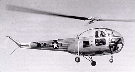
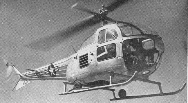
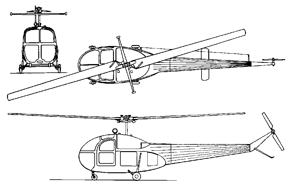
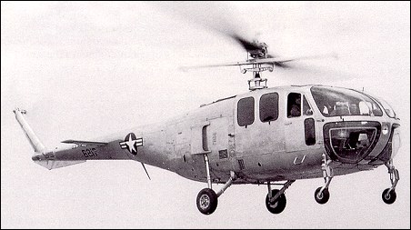
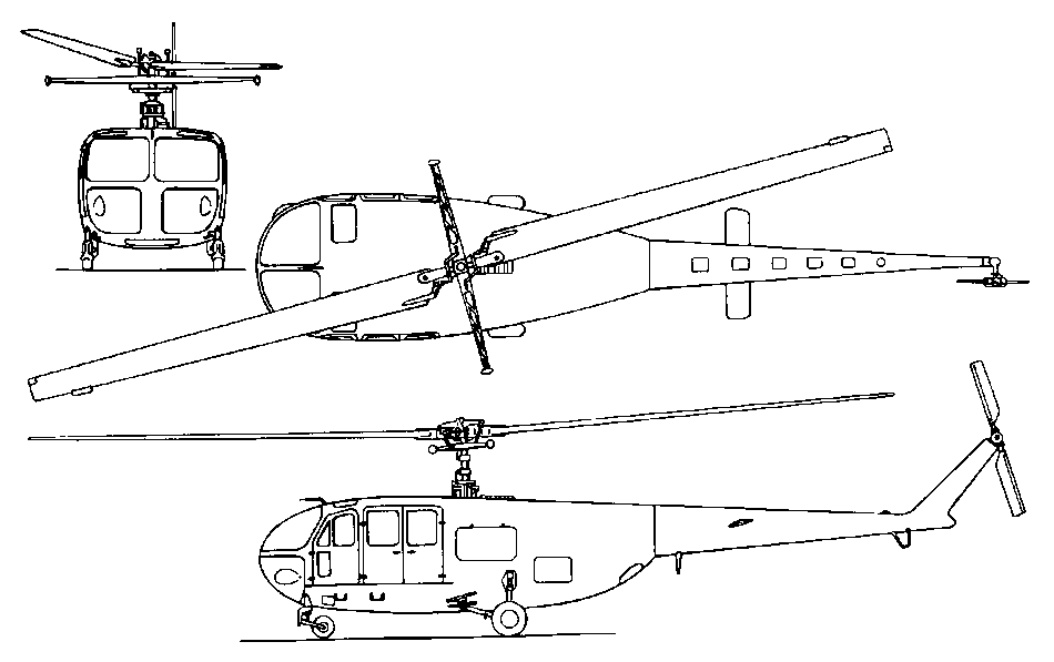
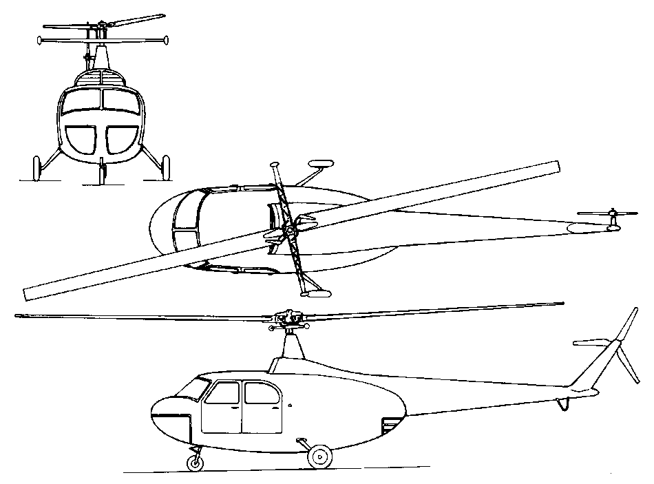
By February 1946 the USAAF issued a to specification for a liaison and observation aircraft. This called for a two-seat, single main rotor type of about 1360kg gross weight and to be powered by a supercharged engine of approximately 260hp. G & A Aircraft Co (Firestone) of Willow Grove, Pennsylvania, won first place and was awarded a contract for three examples of its 100hp Continental A100 powered XR-14-GA (s/n 46-527/529) which were never built. Bell, with its Model 54 proposal, won only second place in this design competition. But at that time, some AAF personnel advocated a contract with Bell and in May 1946 action was initiated for the building and development of three examples of the Model 54 under the designation XR-15-BE (to be redesignated XH-15-BE in 1948). The formal contract was signed a few weeks later. The XR-15 was to be developed both for the Air Force and Army Ground Forces. The Model 54 was an all-metal four-seat helicopter using the same basic rotor system employed in other Bell models, featuring a two-blade rotor with stabilising bar. Power was provided by one 275hp Continental XO-47-5 engine located at the bottom of the rear cabin. Accommodation was provided for a crew of two seated side-by-side in a largely glazed cabin. It had a semi-monocoque fuselage reinforced with stiffeners and fitted with a horizontal stabiliser, and a tricycle (later quadricycle) non-retractable undercarriage. The two-bladed anti-torque rotor was fitted on the starboard side. The aircraft were initially designated XR-15, but this had been changed to XH-15 by the time the first example made its maiden flight in March 1948. Three aircraft were built (s/n 46-530-532) and tested but no production contracts followed. Though funded by the Army Ground Forces (AGF) the XH-15 was evaluated almost exclusively by the Air Force, the latter service having taken control of several AGF aviation projects following the 1947 creation of the USAF. All three examples acquired were used by the Army as high altitude research vehicles until development of the Model 54 came to a halt at the end of 1950. They were stricken from the inventory in the early 1950s. No XH-15 has survived.
In 1946, Bell developed a new general utility helicopter of larger dimensions than the Model 47, as the Model 42, and a military version, the Model 48. The general configuration was a two-blade rotor with stabilising bar, three-wheel non-retractable undercarriage and five-seat cabin with car-like windscreen and doors. The engine was a 540hp Pratt & Whitney R-1340-AN-1 Wasp radial mounted horizontally in the rear fuselage with radiator air intake on top. Alternative equipment included flotation gear for water operation (which was tested on aircraft s/n 46-215), rescue hatch and hoist, litters and life rafts. The USAAF ordered two prototypes of a military derivative, the Model 48, designated XR-12-BE (s/n 46-214/215) as well as a static test airframe. A first production batch of thirty-four examples (R-12A-BE, s/n 47-491/524) was ordered but never built. This order was cancelled in 1947. Meanwhile, the USAAF had ordered a prototype of an enlarged variant, designated XR-12B-BE (s/n 46-216), able to carry up to ten people. This prototype, known as the Model 48A, was followed by a batch of ten similar service trials YR-12B-BE (s/n 46-217/226) with the more powerful 600hp Pratt & Whitney R-1340-5 5 Wasp. The YH-12B was different in shape and the undercarriage had four wheels (wheel base 3.30m; wheel track 2.13m). The wider cabin had separate doors for the crew and passengers and the nose was nearly all-glazed. Horizontal stabilisers were fitted each side of the tail boom. The anti-torque rotor was now located on the port side of the tail-boom end. At the time, the approximate cost of the YR-12, less government-furnished equipment, was estimated at $175,000. Initial deliveries of the YR-12 were scheduled for the summer of 1946. However, Bell was faced with serious engineering difficulties with the prototype. Serious blade weaving and rotor governor trouble were encountered in the main rotor system. In April 1946, Bell accepted the assistance of the Propeller Laboratory at Wright Field to overcome these problems. In May 1946, the USAAF considered that the YR-12 ‘was going to require considerable development and time delay before it was a successful ship’ and procurement of the heavier Sikorsky S-51 was then considered. Delivery of the first YR-12 was in September 1946. Flight tests went smoothly but no production batches of the H-12 were ordered. In 1948, the Bell Model 48 and 48A were respectively re-designated XH-12-BE, XH-12B-BE and YH-12B-BE. They were used for a variety of test programmes before being withdrawn from use. None of them is known to have survived.
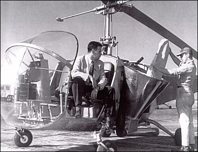
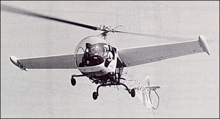
Developed from the Model 30 (third prototype configuration), the Bell Model 47 was ordered for the US Army and Navy towards the end of World War II and first flew in 1945. The pre-production model had a 178 hp Franklin engine driving a two-blade wooden main rotor, two side-by-side seats, open cockpit (but later removable transparent bubble), four-leg wheel u/c, open frame rear fuselage with tail skid (later tubular tail rotor protector), ventral fin and and a car-type. The prototype (NC41962/NC1H) first flew on 8 December 1945. Only ten were built.
On 8 March 1946 this was awarded the first Approved Type Certificate issued for a civil helicopter anywhere in the world. Licensed by the Federal Government and manufactured under Helicopter Type Certificate One. The A and B models used the enclosed body In 1947 the USAAF procured 28 of the improved Model 47A, powered by 117kW (157-hp) Franklin O-335-1 piston engines, for service evaluation: 15 were designated YR-13, three YR-13As were winterised for cold-weather trials in Alaska, and the balance of 10 went to the US Navy for evaluation as HTL-1 trainers. Little time was lost by either service in deciding that the Model 47 was an excellent machine, and the orders began to flow in. The US Army’s first order was issued in 1948, 65 being accepted under the designation H-13B; all US Army versions were later named Sioux. Fifteen of these were converted in 1952 to carry external stretchers, with the designation H-13C. Two-seat H-13Ds with skid landing gear, stretcher carriers, and Franklin O-335-5 engines followed, and generally similar three-seat dual control H-13Es. The H-13G differed by introducing a small elevator, and the H-13H introduced the 186kW Lycoming VO-435 engine. Some of the H-13Hs were used also by the USAF, as were two H-13Js with 179kW Lycoming VO-435s acquired for the use of the US President. Two H-13Hs converted for trial purposes, with an increased-diameter rotor and 168kW Franklin 6VS-335 engine, were designated H-13K. In 1962 US Army H-13E, -G, -H and -K aircraft were redesignated with the prefix letter O, for observation. US Air Force H-13Hs and H-13Js were given the U prefix as utility helicopters. Later acquisitions were the three-seat OH-13S to supersede the OH-13H, and the TH-13T two-seat instrument trainer. US Navy procurement began with 12 HTL-2s and nine HTL-3s, but the first major version was the HTL-4, followed by the HTL-5 with an O-335-5 engine. HTL-6 trainers incorporated the small movable elevator. The HUL-1 was acquired for service on board ice-breaking ships, and the final HTL-7 version for the US Navy was a two-seat dual-control instrument trainer with all-weather instrumentation. In 1962 the HTL-4, HTL-6, HTL-7 and HUL-1 were redesignated respectively TH-13L, TH-13M, TH-13N and UH-13P The 47B-3, a utility and agricultural model, had an open sports-car style body and it was from this design that the goldfish bowl moulded canopy was derived.
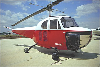
Bell 47B
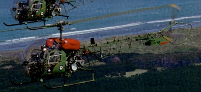
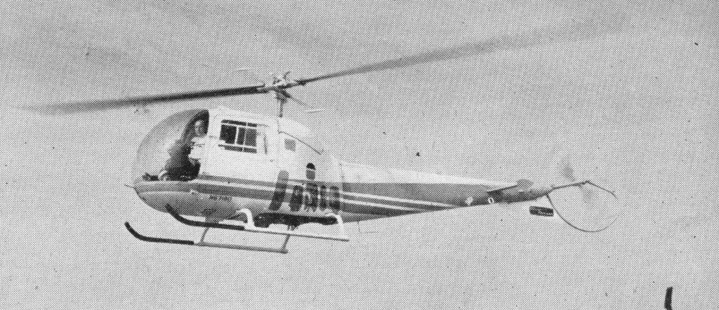
In parallel with production of military aircraft, by both Bell and its licencees, there were civil versions for a wide variety of purposes. These have included the Model 47B (equivalent to the military YR-13/HTL-1), and the agricultural/utility Model 47B-3 with open crew positions. Available in 1948, this model was the crop-dusting variant featuring a fully open cockpit and bins were affixed aft of the cabin and could carry 180kg of dust. The 47B was powered by a vertically mounted 175hp Franklin 6ALV-335 six-cylinder engine. The enclosed cabin, seating two side-by-side, featured two car-like doors. A total of 78 Model 47Bs (including 47B-3) were produced.
Two Bell 47B-3’s used by B.E.A. had plexiglass cabin, covered fuselage, and 178 hp Franklin 6V4-178-B32 engines.
Bell 47B-3
Early in 1948, the Model 47B was superseded by the Model 47D (FAA certified in February 1948) which incorporated improvements, including the plastic bubble-like cabin, the top of which could be removed to provide an open cockpit. In 1949, a new sub-variant appeared, the Model 47D-1 utility helicopter with an openwork tail boom capable of carrying three people or 225kg of payload. The same year, Bell helicopters began to be used on air mail services in Chicago and a Bell 47 set a new altitude record with 5654m as well as a new speed record with 215.45km/h. In 1950, a Bell 47D-1 became the first helicopter to fly over the Alps, and in Belgium the first European postal service by helicopter was set up by Sabena on 21 August, 1950. At the end of the same year, Bell 47s were used to take precise measurements over the Niagara Falls. On 17 September, 1952, Bell pilot, Eiton J. Smith set the world’s straight line distance record for helicopters without payload (Class-E) at the controls of a Model 47D-1 registered N167B, flying nonstop from Hurst (Texas) to Buffalo (New York): 1958.37km in 12hr 57min. On 2 September, 1956, at the National Aircraft Show in Oklahoma City, an H-13H flown by an Army pilot stayed in the air for 57hr and 50min, an unofficial world’s record. The introduction of the Model 47G (granted an FAA certificate in 1953) combined the three-seat capacity of the Model 47D-1 with a 149kW Franklin engine which, through a two-stage planetary transmission system, drove a main rotor of laminated wooden blades with steel leading edges, a tail rotor and a cooling fan. This helicopter had a synchronized elevator directly linked to the cyclic pitch control lever, an improvement which gave better stability and an increased margin of centre-of-gravity travel. The landing gear consisted of two skis 2.88 metres apart, and, if needed, quick-change flotation gear could be fitted. In the former case, two small wheels assisted handling on the ground. The service designations were H-13G in the United States Air Force, HTL-6 in the United States Navy. The designation 47G-1 is that given to the prototype of the 47J equipped with a Lycoming 250hp derated engine.
A Bell 47G-2 landed on the summit of Mt.Blanc (15,770 ft) with two occupants.
Bell 47G-3B-1
Substitution of the similarly powered Avco Lycoming VO-435 resulted in the Model 47G-2 (H-13H). A 179kW VO-435 engine brought the changed designation Model 47G-2A, followed in 1963 by the wider cabin Model 47G-2A-1 with improved rotor blades and increased fuel capacity. Other engine installations included a 168kW supercharged Franklin 6VS-335-A (Model 47G-3); 209kW turbocharged Avco Lycoming TVO-435 (47G-3B); and normally aspirated Avco Lycoming VO-540 and VO-435 engines in the three-seat utility Model 47G-4 and Model 47G-5 respectively. A two-seat agricultural version of the latter was known as the Ag-5, and a civil version of the USAF’s H-13J VIP transport was marketed as the Model 47G-4 and Model 47G-5 respectively.
Bell 47G-2 Wing Ding
The Model 47G-2 registered N6723D and nicknamed “Wing Ding” was converted under the leadership of Jan Drees and flown by Floyd Carlson and Lou Hartwig in 1963. The purpose of the Wing Ding programme was to develop an aircraft which would lift very large payloads in excess of its hover capability, taking advantage of running take-offs and landings. In addition to the wing the rotor’s mast angle could be varied in flight.
Bell 47H
Introduced in 1955, the Model 47H was a deluxe version of the Model 47G. It had an enclosed sound-proofed, 3 seat cabin. The cabin had leather upholstery throughout as well as a leather covered dashboard grouping all electrical switches and carburettor controls. The metal monocoque tail boom contained a luggage compartment. The cabin’s width has been increased to 1.52 metres, so that motor vehicle-size seats can be used. With a 200hp engine, the Bell 47H was not a commercial success.
Bell 47J-2A
First proposed in 1956, the Model 47J was a four-seat utility version of the Model 47G civil version of the USAF’s H-13J VIP transport, powered by a 220hp derated Lycoming VO-435. The enclosed cabin sat the pilot centrally in front and three passengers on a cross bench behind. This bench could be removed to allow the installation of two stretchers. The left door could also be removed for an internal electrically-powered hoist. Alternative skid or pontoon landing gear could be fitted and metal rotor blades were optional permitting a loaded weight of 1290kg. Larger capacity fuel tanks (182 litres) could also be installed providing an extended range of 400km. All the mechanical parts were the same as in the 47G-2. The soldered-tube tail is replaced in the 47J by a monocoque beam. The central section was still made of tubes, but was streamlined. This model was also built under licence by Agusta with 152 aircraft built. Sub-variants were:
Model 47J-1 – this sub-variant was similar to the Model 47J but was powererd by a Lycoming VO-435A.
Model 47J-2 and J-2A “Ranger” – introduced in 1960, this sub-variant was similar to Model 47J but had a 305hp (derated to 240hp) Lycoming VO-540-B1B, metal rotor blades, hydraulic power controls and a gross weight of 1290kg. The Model 47J-2A of 1964 was produced in Italy by Agusta.
Model 47J-3 “Super Ranger” – this variant, produced by Agusta, was powered by a Lycoming VO-540 derated to 260hp. It differed from the standard J-2A in having a modified main transmission able to absorb greater power input. A special ASW version was designed for the Italian Navy with new instrumentation, high efficiency rotor brake and armed with a single Mk.44 torpedo.
Model 47J-3B-1 – this sub-variant produced by Agusta was a high-altitude version powered by a 270hp Lycoming TVO-435-B1A and equipped with an exhaust-driven supercharger which maintained sea level conditions up to 4260m. This model also had a high-inertia rotor and servo-control on the pitch control systems.
1959 Bell 47J
The 1959 version of the Bell 47J Ranger had a modified tail-rotor control to simplify maintenance. Larger drag-links are required for the metal blades of the main rotor. B 1959, over 2000 Bell 47s had been built.
The 47J “Ranger” is the first helicopter to have crossed the Andes by way of the Christo Paso. This flight was made at a height of 5180m, with a total weight of approximately 68kg below the helicopter’s own maximum gross weight. HUL-1 is the U.S. Navy designation. Experimental versions have been numerous. Perhaps the two most important were the turbine Bell Model 201 (service designation XH-13F) and the armed Bell Model 207 Sioux Scout. Bell’s production of Model 47s eventually came to an end in late 1973, versions of the Model 47G-5 being the last to be built. 4,018 were built in 24 different basic configurations. Of the many different models built only two of the commercial versions, the Bell 47G-2 and the Bell 47G-3B-l, had production runs in excess of 300 (334 and 337 respectively).
In 1952 Agusta SpA of Italy was granted a licence to build the Bell 47 and produced its first 47G in 1954. Since then Agusta has built over 1000 G (from 1954 to 1976) and J marks. Agusta produced a three-seat version as the EMA 124.
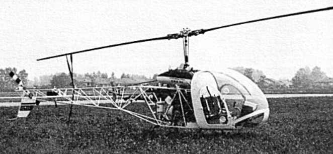
Agusta-Meridionali EMA.124
The Agusta-Meridionali EMA.124 Bell 47 derivative had three-seats, an open frame rear fuselage, skid u/c and one 305hp Textron Lycoming VO-540-B1B3 piston engine. Intended for production by Elicotteri Meridionali SpA, one prototype, I-EMAF, was built, first flown on 28 May 1970.
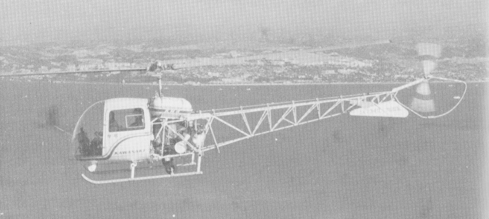
Kawasaki in Japan received a licence in 1953, and the Kawasaki-Bell 47G3B-KH-4 first flew as a type in 1962. Being a development of the Bell 47 G3B by Kawasaki, the type features a four-seat cabin layout, modified instrument and control systems, and a 260 hp Lycoming.
Kawasaki KH-4
In August 1964 it was reported that the British Army was buying 150 Bell 47G three-seat, similiar to the US Army OH-13S Sioux, but with 270 hp Lycoming TVO-435 engines. The first 50 were to be built in Italy by Agusta, and the next 100 by Westland Aircraft in Britain. The unit cost was about $50,000.
The Model 47 was built under licence by Westland in the UK (the 47G-2 for the British Army) with the name Sioux.
In addition there have been specialised conversions by at least two American companies, including a high-performance Carson Super C-4, and a number of El Tomcat agricultural aircraft developed by Continental Copters Inc. Turboshaft conversions of several models have been produced by Soloy in the USA.
47 Initial prototype, 10 built. Car-type cabin Engine: Franklin, 178 hp Main rotor: two-blade wooden, Seats: two side-by-side
47A / YR-13 / YH-13 / HTL-1 USAF version of Model 47 as YR-13 with enclosed rear fuselage and tail boom, powered by one 175hp Engine: Franklin O-335-1, 175hp 28 built.
47A / YH-13A Three YH-13 modified for cold weather operations. Engine: Franklin O-335-1, 117kW (157-hp)
47B Two-seat commercial Model 47 with enclosed tailboom, fully enclosed fuselage with stepped windshield, under-nose transparencies and two car-type doors, four-leg u/c. Prot NX41967. Engine: Franklin 6V4-178-B3, 178hp Rotor diameter: 10.26m Gross weight: 992kg Empty weight: 626kg Cruising speed: 128km/h Rate of climb: 290m/min Service ceiling: 2960m Range: 320km Seats: two side-by-side
47B-3 Model 47 for crop dusting with modified open cockpit, engine compartment fairing, and externally mounted dusting hoppers. Engine: Franklin 6V4-178-B32, 178hp Payload: 180kg of dust.
47C / H-13G U.S.A.F. version
47D Model 47B-3 with improved plexiglass, bubble canopy, new wheel installation with brakes, 24 volt electrical system, modified fuel system, optional float u/c (47D-S) and 178hp Franklin 6V4-178-B32 engine.
47D / H-13B Sioux / HTL-2 Military model similar to civil 47D with four-leg u/c, bubble canopy with removable top, covered rear fuselage and dual controls. 61 built. Engine: Franklin O-335-3, 200hp
47D / H-13C Sioux H-13B with uncovered rear fuselage and skid u/c with external medevac litter fittings. 16 built.
47D / H-13D Sioux H-13C with single pilot controls. 88 built. Engine: 200hp Franklin O-335-5 Rotor dia.: 35 ft. 11 in. Weight: 2,350 lb Max speed: 100 mph Seats: 2
47D / H-13E Sioux / OH-13E H-13D with dual controls, modified main and tail gearboxes and main transmission. 49 built. Engine: Franklin O-335-5B, 178hp Seats: 3
47D-1 Three-seat Model 47D with open frame fuselage, new canopy, gravity-feed fuel system, ventral fin, roller-bearing transmission, 29-USG fuel capacity, reduced equipment and increased useful load. 937kg TOGW.
47D-1 / HTL-4 / TH-13L US Navy version of Model 47D-1. Later TH-13L. 46 built. Rotor diameter: 10.72m Overall length: 12.56m Fuselage length: 8.33m Height: 2.79m Loaded weight: 943kg Empty weight: 626kg Maximum cruising speed SL: 147km/h Rate of climb: 313m/min Service ceiling: 3965m Hover ceiling in ground effect: 1920m Range (75% power): 342km Seats: 3 Fuel capacity: 29-USG
47D-1 / HTL-5 HTL-4 with 200hp Franklin O-335-5 engine. Payload: 225kg Seats: 3
Bell 47D-S Engine: Franklin 6V4-178-B32, 178hp Undercarriage: floats
47E / HTL-3 Two-seat Model 47D with 200hp Franklin 6V4-200-C32 engine, 1060kg TOGW, 33-USG fuel capacity, optional open cockpit.
47G Three-seat Model 47D with 200hp Franklin 6V4-200-C32AB engine, skid u/c, small tailplane with endplates, relocated battery, revised tail rotor gearbox, synchronised elevator and relocated 43-USG ‘saddle’ fuel tanks 1060kg TOGW. Entered production 1953
47G-2 Model 47G with 200hp Lycoming VO435-A1A engine, relocated cyclic hydraulic boost controls, bonded metal rotor blades and 1105kg TOGW. Also built by Kawasaki.
Bell 47G / H-13G Sioux / HTL-6 / TH-13M / OH-13G US Navy dual control training version of H-13G. Later TH-13M. Military model similar to 47G-2 with increased fuel and external stretcher fittings. 265 built. Engine: Franklin, 200 hp / 149kW Rotor diameter: 10.72m Overall length: 12.62m Fuselage length: 8.33m Height: 2.87m Loaded weight: 1067kg Empty weight: 651kg Maximum speed: 138km/h Cruising speed: 113km/h Initial rate of climb: 238m/min Service ceiling: 2718m Hover ceiling in ground effect: 1098m Range: 341km Seats: 3 landing gear two skis Skid width: 2.88 m
Bell 47G-1 Engine: Lycoming 250hp derated
Bell 47G-2 / H-13H Sioux / UH-13H H-13G with 250hp Lycoming VO-435-23 engine, improved skid u/c and all-metal bonded rotor blades. 468 built. Engine: Avco Lycoming VO-435-23, 250hp
47G-2A Three-seat Model 47G with 240hp Lycoming VO-435-A1E engine, 1285kg TOGW. Also Kawasaki model.
47G-2A-1 47G-2A with fuel capacity inc. from 43-USG to 61.6-USG.
Bell 47G-2 Wing Ding
Bell 47G-3 / H-13K Sioux Civil and military model 47G with 225hp Franklin 6VS-335-A engine, longer rotor blades and 14-inch longer tailboom. 1195kg TOGW. Engine: 225hp Franklin 6VS-335-A supercharged TOGW: 1195kg
47G-3B / OH-13S Sioux Civil and military Model 47G-3 with turbocharged 260hp Lycoming TVO-435-A1A and 1285kg TOGW. 576 built. Engine: 260hp Lycoming TVO-435-A1A Length : 31.562 ft / 9.62 m Height : 9.285 ft / 2.83 m Rotor diameter : 37.238 ft / 11.35 m Max take off weight : 2954.7 lb / 1340.0 kg Max. speed : 91 kt / 169 km/h Service ceiling : 17487 ft / 5330 m Range : 274 nm / 507 km Seats: 3
47G-3B1 Model 47G-3B with 270hp turbocharged Lycoming TVO-435-B1A engine, 8-inch wider 3-seat cabin, 61.6-USG fuel capacity. 1330kg TOGW. Built also by Westland and Agusta. Engine: Lycoming TVO-435-B1A, 260 hp Max speed: 105 mph Range: 273 sm Rotor: 2-blade, 11.32-rn (37 ft 2 in) Cruise @ 65%: 80 mph Endurance: 3 hr TOGW: 1330 kg Useful load: 470 lb Seats: 3 Fuel capacity: 61.6-USG
47G-3B2 Model 47G-3B1 with turbocharged 280hp Lycoming TVO-435-G1A. 1330kg TOGW. Engine: Lycoming TVO-435-G1B, 280 hp Rotor: 2-blade, 11.32-rn (37 ft 2 in) Max speed: 91 kt Cruise: 73 kt Range: 215 nm Empty wt: 858 kg MTOW: 1340 kg
47G-3B-2A Engine: Lycoming TVO-435-F1A, 280 hp Rotor dia: 37 ft 1.5 in / 11.32 m Fuselage length: 37 ft 7 in / 9.63 m Empty weight equipped: 1893 lb / 858 kg MTOW: 2950 lb / 1338 kg Cruise 5000 ft / 1525m: 73 kt / 84 mph / 135 kph ROC SL: 990 fpm / 302 m/min Service ceiling: 19,000 ft / 5790 m Range max fuel 6000ft / 1830m, no res: 214 nm / 247 mi / 397 km Seats: 3 side by side External cargo: 1000 lb / 454 kg
47G-3B2 / TH-13T Two/three seat military instrument trainer with extra IFR equipment. 417 built.
47G-3B2A Model 47G-3B2 with TVO-435-F1A engine and 11-inch wider cabin
47G-4 Model 47G with 260hp Lycoming VO-540-B1 B3 engine, 61.6-USG fuel, hydraulically assisted controls and 1330kg TOGW. Engine: Lycoming VO-540-B1 B3, 260hp TOGW: 1330 kg Fuel capacity: 61.6 USG Seats: 3
47G-4A Model 47G-4 with engine uprated to 280hp.
Bell 47G-4 Ag-5 agricultural version Engine: Lycoming VO-540-B1 B3, 260hp Fuel capacity: 61.6 USG Seats: 2
47G-5 / H-13J Economy 2-seat version of 47G-4 with 12 volt electrical system. 1285kg TOGW, 28-USG fuel capacity. Can be upgraded to 3-seat configuration with synchronised elevator mod. Engine: Avco Lycoming VO-435, 260 hp TOGW: 1285 kg Fuel capacity: 28 USG Seats: 2-3
47G-5A 3-seat Model 47G-5 with 61.6-USG fuel tanks and 11-inch wider cabin. Engine: Avco Lycoming VO-435-B1A, 198-kW (265-hp) Max speed at sea level: 196 km/h (105 mph) Cruise: 137 km/h (85 mph) at 1525m (5,000ft) Service ceiling: 3200m (10,500ft) Range max fuel: 412 km (256 miles) Empty equipped weight: 786 kg (1,732 lb) MTOW: 1293 kg (2,850 lb) Main rotor dia: 11.32m (37ft 1½ in) Tail rotor diameter: 1.78m (5ft 10in) Length, rotors turning 13.3m (43ft 7½in) Height: 2.84m (9ft 3¾ in) Main rotor disc area: 100.61 sq.m (1,083 sq ft). Seats: 3 Fuel capacity: 61.6 USG
Bell 47H Engine: 200 h.p. Franklin 6V4-200-C32 Rotor diameter: 35 ft. 1.5 in. Rotors: 2-blade main; 2-blade tail Fuselage length: 31 ft. 4 in Loaded weight: 2,350 lb. Max. speed: over 100 m.p.h. Ceiling: 10,600 ft. Typical range: over 200 miles at 95 mph with full load. Cabin width: 1.52 m Seats: 3.
47H-1 Model 47G with fully clad fuselage, wider three-seat deluxe cabin and rear baggage stowage locker, contoured 35-USG fuel tanks, modified skid u/c. 1060kg TOGW. Rotor diameter: 10.72m Overall length: 12.62m Fuselage length: 8.33m Height: 2.82m MTOW: 1067kg Empty weight: 681kg Fuel capacity: 35 USG Maximum speed: 161km/h Cruising speed: 142km/h Initial rate of climb: 250m/min Service ceiling: 3660m Hover ceiling in ground effect: 1310m Range: 339km Number of seats: 3
47J Formerly 47G-1 Four-seat development of Model 47H with single pilot seat and rear 3-place passenger seat. Powered by one 220hp Lycoming VO-435-A1B, 1157kg TOGW and 35-USG fuel capacity.
47J / H-13J Model 47J for USAF with 240hp Lycoming VO-435-21.
47J / HUL-1 Model 47J for US Navy with 260hp Lycoming VO-435-B1B. Later UH-13P. Also HUL-1G (HH-13Q) for USCG. 25 built.
Bell 47J / H-13J / UH-13J Engine: Lycoming VO-435-21, 240hp
47J-1 Model 47J with VO-435A engine. Engine: Lycoming VO-435-A1B, 220hp Fuel capacity: 35 USG Opt fuel tanks: 182 lt Length : 31.562 ft / 9.62 m Height: 9.285 ft / 2.830 m Rotor diameter: 37.238 ft / 11.35 m Max take off weight: 1157kg Metal rotor blades option MTOW: 1290kg Max. speed: 91 kt / 169 km/h Service ceiling: 17487 ft / 5330 m Range: 274 nm / 507 km Seats: 4
47J-2 Ranger Model 47J with 240hp VO-540-B IB engine, metal rotor blades, fixed stabiliser, hydraulic controls, blue tinted bubble and windows, 48-USG fuel capacity and 1285kg TOGW. Originally 47G-1 Engine: Lycoming VO-540-B1B, 305hp (derated to 240hp) Gross weight: 1290kg Fuel capacity: 48 USG Seats: 4
47J-2A Model 47J-2 with 260hp Lycoming VO-540-B 1 B3 engine, collective boost system and 1330kg TOGW. Built by Agusta.
47J-3 Naval Model 47J-2A with strengthened transmission, improved rotor brake and underslung torpedo. Agusta built.
Bell 47J-3 Super Ranger Engine: Lycoming VO-540 derated to 260hp
47J-3B1 Model 47J with turbocharged Lycoming TVO-435-B1A engine for high altitude operation and modified servo control system 1330kg TOGW. Lycoming TVO-435-B1A 270hp @ 4260m Rotor diameter: 11.32m Fuselage length: 9.87m Height: 2.83m Take-off weight: 1340kg Empty weight: 845kg Maximum speed at sea level: 169km/h Cruising speed at 1525m: 138km/h Initial rate of climb: 276m/min Service ceiling: 5340m Hover ceiling in ground effect: 5030m Hover ceiling out of ground effect: 3720m Range: 338km Seats: 4
47K / HTL-7 / TH-13N US Navy 2-seat trainer based on HUL-1 with modified cockpit and IFR instrumentation. 240hp Lycoming O-435-6 engine. 1157kg TOGW, 35-USG fuel capacity. Later TH-13N. 18 built. Engine: Lycoming O-435-6, 240hp TOGW: 1157kg Fuel capacity: 35 USG Seats: 2
47L / HUL-1M / UH-13R Experimental Model 47J with 250shp Allison YT-63-A-3 turboshaft and 1285kg TOGW. First a/c Bu. 149838 FF 6 Jan, 1961. Later UH-13R. 2 built.
Kawasaki-Bell 47G3B-KH-4 Engine: Lycoming TVO-435-D1A, 270 hp Main rotor diameter: 37 ft 1.5 in / 11.32 m Fuselage length: 32 ft 7.25 in / 9.93 m Empty weight: 1890 lb / 757 kg MTOW: 2850 lb / 1292 kg Cruise speed: 76 kt / 87 mph / 140 kph ROC S/L: 850 fpm / 260 m/min Range max fuel: 186 nm / 214 mi / 345 km Seats: 4
Continental Copters 47G-2 El Tomcat Agricultural conversion by Continental Copters with single seat cockpit and two large external hoppers plus underslung spray bars. Seats: 1
Texas Helicopters M-74 Wasp Conversion by Texas Helicopters
Texas Helicopters M-79T Hornet Conversion by Texas Helicopters
Agusta EMA 124 3 seat development of 46G Engine: VO-540, 250 hp Seats: 3
With the Model 47 in production Bell concluded that there was a market for a larger helicopter with seating for five or six people. The Model 42 was a streamlined all-metal helicopter which could carry five people: the pilot’s and co-pilot’s seat were situated in the front of the cabin, and a bench seat for three passengers was located in the rear. The Model 42 had a completely enclosed fuselage pod and boom and a fixed tricycle undercarriage, and a stabilising bar on the main rotor. It was powered by one 450hp Pratt & Whitney R-985 Wasp Junior engine, mounted horizontally behind the cabin driving a two-blade symmetrical aerofoil wooden rotor. Cooling was assured by a large airscoop located at the root of the main rotor mast. The rotor had a reduction gear ratio of 8.987:1. In addition to the free-wheeling coupling, the transmission included a rotor brake. A three-bladed anti-torque tail rotor, also made of laminated wood, was on the starboard side of the semi-monocoque tail boom. Access to the cabin was via two car-like doors. The undercarriage was of the fixed tricycle type and fuel capacity was 65 US gal. The Model 42 design was a monstrous tangle of cables winding around drums and full of unexpected difficulties, and responsibility of the development was transfered to the Gardenville team. After much work and re-design, Arthur Young and Bartram Kelley got most of the bugs out of the prototype (c/n 1, NX33540) and made it fly properly. In December 1946, the Model 42 was displayed at the Cleveland Air Show. Two more examples were assembled and tested (c/n 2, NX42063; and c/n 3) but no firm orders were placed and the development of the Model 42 came to a halt. Nevertheless, the characteristic silhouette of the Model 42 would re-appear months later with the military Model 48. None of the Model 42 seem to have survived.
Model 42 Engine: one 450hp Pratt & Whitney R-985 Wasp Junior Rotor diameter: 14.48m Maximum weight: 2315kg Useful load: 656kg Maximum speed at sea level: 200km/h Cruising speed 75% pwr: 160km/h Service ceiling: 3965m Range: 480km
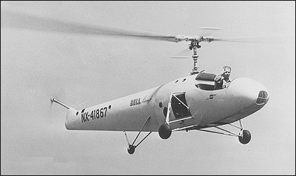
By the autumn of 1941, Arthur M Young had been testing helicopter scale-models on his farm in Pennsylvania for some thirteen years. After this period of research, many failures and his big breakthrough with the invention of the stabiliser bar, Young had perfected a design that would appeal to a manufacturer. Young’s first attempts at interesting aircraft companies in his machine met with little enthusiasm until one of his friends visited Bell’s factory. This led to an appointment for a demonstration on 3 September, 1941. Larry Bell and Arthur Young reached an agreement and, on 24 November, 1941, Young and his assistant, Bart Kelley, arrived at Bell to supervise the initial building of two prototypes as specified in the contract. On 23 June, 1942, Young and his team (some fifteen people) were installed in an old Chrysler agency and garage in Gardenville, a suburb of Buffalo. Dave Forman was assigned to supervise the project. The Model 30 structure was made of welded tubes with a four-legged undercarriage made of 3in aluminium tubing. The 160hp Franklin six-cylinder horizontally-opposed air-cooled engine was mounted vertically behind the cockpit within a steel-tube framework. The main two-blade rotor hub was mounted on a transmission mast by universal joint and was provided with a stabilising bar below and at right angles to the blades which were rigidly connected to the hub. This bar acted as a flywheel on a hinge. It kept the rotor blades level and independent from the movements of the fuselage, solving the problem of stability. The main rotor drive was done through a centrifugal clutch and a two-stage planetary transmission with a 9:1 reduction ratio. The blades, of symmetrical aerofoil section, were made of solid wood with a steel insert in the leading edge. The two-blade tail rotor (also made of solid wood) was mounted on a thin tube at the end of the fuselage. The roll-out of the first Model 30 (c/n 1, later to be registered NX41867) took place on 24 December, 1942; a secretary broke a bottle of champagne on the fuselage and the aircraft was named Genevieve. That day, the engine was run up at 150rpm. The first flight occurred on 29 December when Young flew the tethered Model 30 at an altitude of 1.5m; the same day Floyd Carlson also flew the aircraft. Early in January 1943, the prototype suffered an accident and its pilot, Bob Stanley, was badly hurt. The aircraft was repaired and on 26 June, 1943, the cable was removed and Carlson took Genevieve on its first free flight. The aircraft performed well and by July 1943 was flying at speeds of over 110km/h. At this time, a three-wheeled undercarriage was installed, the fuselage was covered and the aircraft was painted blue overall, so that it could be used for demonstration flights. While flights of the Model 30 No.1 were underway, aircraft No.2 was being built. Several modifications were introduced in this machine: new undercarriage, semi-monocoque fuselage and new tail rotor mounting, and an enclosed cockpit, with car-like doors, for the pilot and one passenger. Unfortunately a setback occurred in September 1943 when the No.1 crashed with Carlson at the controls. Carlson was unhurt but the badly damaged aircraft had to be rebuilt. It was flying again within six months. In late September 1943, aircraft No.2 (registered NX41868) replaced No.1 as the test vehicle. One of the first passengers to fly in this aircraft was Larry Bell. In 1944, Bell began a demonstration programme with aircraft No.2 which made its public debut in March 1944. On 10 May, Floyd Carlson flew the aircraft indoors in a Buffalo armoury before Civil Air Patrol pilots and cadets. By the spring of 1944, aircraft No.1 had been rebuilt and was designated No.1A. This helicopter was the star attraction at a soldier’s benefit show, staged at Buffalo’s Civil Stadium on 4 July 1944. On 5 January, 1945 the first rescue mission ever made by a Bell helicopter took place when Jack Woolams baled out of a P-59 Airacomet in trouble near Lockport. Floyd Carlson and Dr. Thomas C. Marriott took off in one of the Model 30s and, guided by Joe Masham flying a P-59, rescued the unfortunate pilot. But the first publicised rescue mission took place two months later, on 14 March, when two ice fishermen were rescued on Lake Erie. Carlson received the Treasury Department Silver Medal for this feat. The construction of a third aircraft introduced several improvements including a four-wheel undercarriage, an advanced instrument panel and a tubular tailboom, but it retained the open cockpit of No.1. This helicopter (c/n 3, registered NX41869) flew for the first time on 25 April, 1945, and performed well, so well that it proved to be the best of the trio to demonstrate, but the open cockpit was a real handicap. To overcome this Young had the idea of covering the cockpit with a Plexiglass bubble thus providing both comfort and outstanding visibility for pilot and passenger. The shape of this aircraft was now very near to that of the Model 47. Two of the Model 30s are still in existence: c/n 1A (NX41867) is on display at the National Air and Space Museum and c/n 3 (NX41869) is owned by Buffalo and Erie County Historical Society Museum, Amhurst, New York.
Model 30 Engine: 1 x Franklin 6-cylinder, 110.4kW / 160hp Main rotor diameter: 9.75m Main rotor: 2-blade wooden Length: 8.22m Height: 2.59m Empty weight: 518kg Crew: 1 Passengers: 1
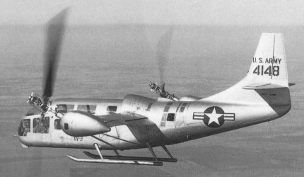
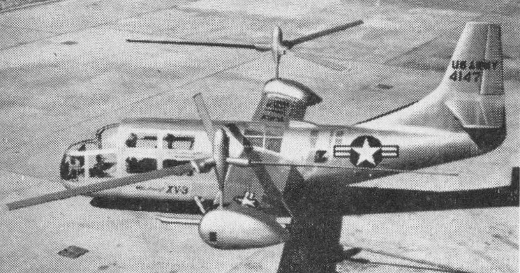
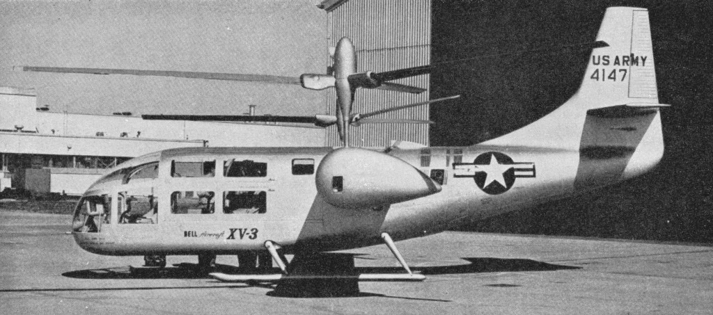
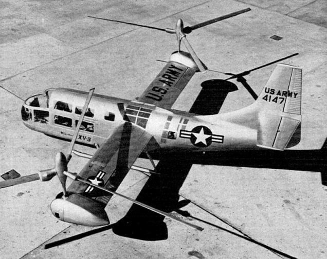
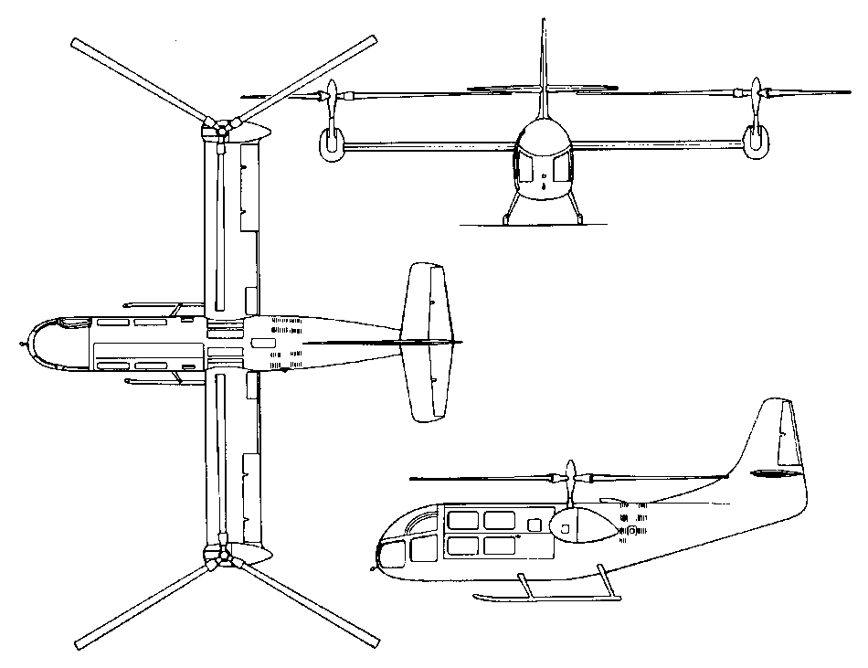
In August 1950, the Air Force and Army announced an official Tilt Rotor design competition. Bell’s proposal for their Model 200 won the competition for the XV-3 (originally designated the XH-33), and Bell was awarded a contract in May 1951. The XV-3 was built and initially flight tested at Bell’s Ft. Worth, Texas, facility. Two prototypes were built, carrying tail numbers 4147 and 4148. The basic configuration was a metal fuselage with the metal wing mounted mid fuselage. A helicopter-like rotor was mounted on each wing tip. The rotor shafts were oriented in a vertical position for take-off, landing and hover like a helicopter, and moved to the horizontal position for forward flight like a conventional aircraft. A single Pratt & Whitney R-985-AN-1 Wasp Junior piston engine, producing 400hp for flight and 450hp for take-off, was located in the fuselage just behind the wing. A series of gearboxes and drive shafts transferred power to the rotors. Fuel was stored in a 380 litres tank located in the fuselage just under the wing. The fuselage length was 9.25m, the wing span was 9.53m, the height was 4.14m, and the wing area was 10.8 sq.m. The maximum speed was predicted to be 252km/h. Three-bladed, fully articulated, 7.63m-diameter rotors were used initially. They were driven through a two speed transmission that could be shifted to a lower gear to allow the rotors to turn at a lower speed while the engine maintained a higher speed for greater cruise efficiency. The rotor tilt was controlled by an electric motor enclosed in a fairing at each wing tip. Each rotor could rotate through a 90-degree arc from vertical to horizontal in 10 to 15 seconds. The pilot could stop or reverse the rotor motion at any point. Steady, stable flight could be maintained with the rotors in any intermediate position. The XV-3 was intended as a research vehicle to evaluate the Tilt Rotor concept and to provide design and test data, but the military contracting rules at the time required that it also be designed and demonstrated with a military mission capability. The XV-3’s military mission was observation, reconnaissance, and medical evacuation. It had mounting points for two litters. Tests confirmed that good propulsive efficiencies for cruise could be obtained using helicopter rotors as propellers by reducing the rotational speed to about half of that used for hover. Only minor design changes were recommended as a result of tests. What the wind tunnel tests did not look at was the impact of the large, slow turning rotors on the aeroelastic and longitudinal stability of the aircraft at cruise speeds. Aeroelastic effects, which are the coupling of the bending motions of various flexible components on the aircraft, plagued the XV-3 throughout its early life. The first XV-3 (serial 54-147) was constructed between January 1952 and December 1954. The aircraft rolled out on February 10, 1955, and following roll out, airframe and control system proof load tests, vibration surveys, and system functional tests were performed. Then, with the XV-3 mounted on a tie down stand, full conversions and operation in helicopter and airplane modes were tested. Ground runs included a rotor stability survey and ten hours of full power operation. These ground tests were completed by August. No major difficulties were noted, and rotor stability checks showed the aircraft to be free of any resonance tendencies.
The first hover flight was made on August 11, 1955, by a Bell test pilot, but limited progress was made in flight testing during the next three years due to continuing problems with wing/pylon/rotor instabilities during flight. The first of these occurred after only one week and 1.2 hours of flight time, during an air taxi test. It resulted in a hard landing, and the XV-3 sustained rotor and airframe damage. While the damage was not extensive, the discovery of the instability raised major concerns. Repairs were made, and several modifications also were made which were felt would eliminate the elastic coupling problem. These included stiffening the rotor controls and adding external struts to make the wing more rigid. The trailing 25 percent of the wing was made to droop during hover to reduce disturbance to the rotor airflow during hover, and also to reduce stall speed to 85 knots, making transitions at a lower speed possible. 200 hours of ground runs and tie down tests were made to evaluate these modifications before clearing the XV-3 to fly again. The next hover flight finally occurred on March 24, 1956. Bell finally began envelope expansion flights in June 1956 and performed a nacelle tilt of 5 degrees on July 11. By July 25, they reached 70 degrees tilt and 150km/h forward speed when another rotor instability was encountered. Flight testing resumed on September 26 after more modifications were made to the rotor system and ground run evaluations were completed. On October 25, during another test flight, 4147 encountered another very severe inflight rotor instability and crashed. The pilot was seriously injured, but survived. Bell took a serious look at the entire rotor system, and decided that the basic design and characteristics of the three-bladed articulating rotor system were unsatisfactory for the XV-3. Prior to resuming flight testing with the second prototype, 4148, Bell made numerous changes. They kept the R-985 engine, despite its limited power, because of its very good reliability record. The flush engine cooling air inlet was replaced with a scoop that spanned across the top of the fuselage, from one wing root to the other. As had been done with 4147, the rotor controls were stiffened and the wing was braced with external struts on the bottom. The number 2 XV-3 was shipped to NASA’s Ames Research Center, where it flew in their 12m x 24m wind tunnel in September and October 1957. Serious flutter problems with the original three blade rotors were confirmed, and Bell decided to replace them with two-bladed, semi-rigid type rotors of 7.3m diameter, mounted on shorter masts. The semi-rigid, versus the fully articulated design, in itself further increased rigidity, which would decrease the possibility of aeroelastic coupling. While in the wind tunnel, pilots were able to practice conversion procedures and gear changes. Further changes to the two bladed rotor/pylon design were still required to eliminate pylon oscillations, but these changes were tested while still in the tunnel, and again appeared to eliminate the problem in all conditions that were tested. The pilots found conversion to be quite easy, but engine gearbox shifting proved to be difficult, requiring considerable manipulation of the pitch controller and throttle throughout the twenty second process. Flight testing of 4148 (serial 54-148) began at Bell on January 21, 1958. Conversions to 30 degree pylon angle and speeds up to 205km/h were accomplished by April 1, 1958. Pilots also demonstrated autorotation to a landing following a simulated engine failure. Helicopter characteristics were rated as good, especially in high speed forward flight, and vibration levels were lower than expected. By May 6, another rotor oscillation was encountered in flight at a 40 degree pylon angle, and the aircraft again was grounded. Bell, the Army, and NACA decided that another series of wind tunnel tests was in order. The 12m x 24m tunnel at Ames Research Center was heavily scheduled through the summer, and the XV-3 sat grounded until being shipped to Ames in September. During this time, Bell conducted analog computer simulations to further analyze the instability problem and recommend configuration changes prior to beginning the wind tunnel tests. During October 1958, the XV-3 finally went into the 12m x 24m foot wind tunnel at NASA Ames, and more refinements resulted. Changes included increasing the control system stiffness to three times greater than original, adding counterweights in to the rotor collective control mechanism, and increasing the blade sweep angle. Flying resumed on December 11, and on December 17, the XV-3 achieved 30 degrees tilt, and on December 18 achieved 70 degrees tilt. After making a few minor rigging corrections, a second flight was made and a full conversion to 90 degrees finally was achieved. The conversion was made in steps, starting at 167km/h in full helicopter mode and finishing at 213km/h in full airplane mode. A second full conversion was made the next day. This was three years after the date projected for full transition at the time of the XV-3’s roll out. Over the next ten weeks, final aerodynamic and control system refinements were made, including adding a large plywood ventral fin to improve the poor directional stability. With all the changes that were made to the rotors and pylons, Bell tried something new to see if the wing really was contributing to the instability. The strut attachments were modified with locking devices that allowed the XV-3 to fly with the supporting struts either locked in place to maintain wing rigidity or loose to provide no support to the wing. They were hydraulically actuated, and the pilot could switch between the two settings in flight. Bell assumed that if the instability resumed with the struts unlocked, then the wing indeed did contribute to the problem. The new device was tested on January 16, 1 959, at rotor angles up to 85 degrees from vertical with no instability problems. On the January 22, the struts were removed and the XV-3 flew up to 220km/h with the rotors 50 degrees from vertical, again with no instability noted. A wheeled landing gear was added to the landing skids, and short take-offs were made on April 13, 1959, using less than 60m of runway, and using only two thirds power. Optimum rotor tilt angle was found to be ten degrees forward of vertical. The first in-flight gear change was made on April 14, 1959, and a forward speed of 220km/h was achieved at a much lower engine speed with an accompanying lower vibration level. The gear change took about ten seconds to accomplish. The process was very similar to shifting a manual transmission in a car, requiring manipulation of the aircraft’s collective control, throttle, and clutch.
By April 24, 1959, the XV-3 was ready for formal evaluation by the military. It was shipped to Edwards AFB for a two month flight evaluation that began on May 14, 1959. The joint Air Force and Army evaluation consisted of 38 flights and a total of 29.6 hours. Forty conversions were made, as were twenty gear shifts to lower the rotor speed while in airplane mode. Also demonstrated were power-off conversions from airplane mode to helicopter mode followed by autorotation to a safe landing. Flights up to 3660m were performed. Air Force and Army evaluators concluded that conversions could be performed easily at all airspeed and fuselage attitudes that were tested. They considered the concept to be operationally practical because of low down wash velocity and temperature, low vibration, reasonable noise levels, and excellent reliability. The XV-3 demonstrated good behavior during stalls, good rolling take-off performance, and good basic controllability without electronic or mechanical stability augmentation. On the negative side, items related to the prop rotor concept included an erratic lateral darting tendency and roll oscillations during hovering in ground effect. A large increase in power was needed as hovering flight was approached. Weak longitudinal and lateral-directional stability was also observed at low speed in helicopter mode, as was excessive blade flapping during longitudinal and directional maneuvering in airplane mode. There was high parasite drag in all configurations at high speeds. And last, the XV-3 displayed a fore/aft surging motion, especially severe in rough air, attributed partly to the use of large, lightly loaded rotors as propellers. Performance was significantly less than predicted and weight had grown. The design empty weight was 1580kg and grew to 1895kg, before the Air Force added 72kg of instrumentation. At a gross weight of 2165kg, only the test pilot and about 190 litres of fuel (half the fuel tank capacity) could be carried. This gave a maximum endurance of one hour. In airplane mode in high gear and full power at 1220m of altitude, cruise speed was 189km/h true airspeed and wing stall was 185km/h. In low gear and full throttle, cruise increased to 213km/h and wing stall was reduced to 174km/h. The XV-3 was dived to 287km/h, which was the top speed due to limits of collective pitch. Short period longitudinal dynamic stability began to deteriorate at 222km/h, and was considered unacceptable at 240km/h. At the completion of Air Force testing, the XV-3 was shipped to NASA Ames where it remained on flight status through July 1962. By the time its flying career ended, the XV-3 had been flown 270 times by 11 pilots for a total of 125 hours. 110 full conversions were made by nine different pilots, six of whom performed the conversion on their first flight.
Flight testing of the XV-3 clearly demonstrated that technology had not yet developed an understanding of the aeroelastic coupling that could occur between the wing and a large, slow-turning rotor located at the wing tips. It wasn’t until the mid-1960s that engineers finally had a relatively complete understanding of the coupling problem, following the development of sophisticated analytical tools and more capable computers. Although the XV-3 demonstrated the feasibility of the Tilt Rotor concept, it was limited because of low power, an unsophisiticated flight control system, and relatively low twist, helicopter-like rotor blades. Several times Bell proposed replacing the powerplant with a Lycoming T-53 turboshaft engine of 600hp and making rotor and control modifications to eliminate the concept-related deficiencies identified during the Air Force evaluation, but the XV-3 never flew again. However, the XV-3’s career was not over yet. Under a NASA contract, Bell continued studying the phenomena of aeroelastic coupling and ways to improve high speed flight. Two additional sets of wind tunnel tests using the XV-3 were performed. The first was done in July 1962, evaluating several changes aimed at increasing maximum speed, improving high-speed flight characteristics, and decreasing the rotor flapping that occurred during maneuvering. The tunnel was run at 240km/h before instabilities set in. Following modifications, the instabilities did not return until 295km/h. Using these results, Bell felt that they finally had a good understanding of the problem. In May 1965, the XV-3 returned to Bell, where further study, modifications, and ground runs were performed between July 1965 and March 1966. It then returned to Ames and again entered the 12m x 24m tunnel for the fourth, and last, time in May 1966. This time, the XV-3 was tested to 365km/h, the limit of the wind tunnel, without encountering any of the oscillations that had plagued the aircraft throughout its career. However, on May 20, while running at maximum tunnel speed and taking the last planned data point, both rotors tore loose following a wingtip fatigue failure, damaging the aircraft and permanently ending the XV-3’s career. Following these events, the XV-3 was placed in storage for many years, spending time at Wright-Patterson AFB and Davis-Monthan AFB. Eventually the U.S. Army Aviation Museum at Fort Rucker, Alabama, acquired it for display. Small size and lack of capital of Platt-LePage Aircraft, along with lack of orders for military aircraft caused the Platt-LePage Aircraft Co. to shut down in August of 1946. The McDonnell Aircraft Co. obtained most of the helicopter patents from Platt-LePage during the liquidation of the company, along with the personnel responsible for the twin engine project. Robert Lichten an ex-Platt-LePage engineer went to Bell Helicopter and developed the Tilt-Rotor idea into the XV-3, an examination of the original patent by Haviland Platt shows a remarkable similarity between the two ideas, and Bell Aircraft eventually paid Haviland Platt for the use of his patent.
Bell XV-3 Engine: 1 x Pratt & Whitney R-985, 330kW / 450hp Type of rotors: 2 x 3-blade combined rotor-propellers Propeller diameter: 7.32m Wingspan: 9.15m / 30 ft Length: 30 ft Take-off weight: 2177kg Empty weight: 1633kg Max speed: 280km/h Ceiling: 3600m Seats: 4
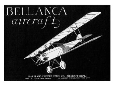
The CE biplane, designed by Guiseppi Bellanca in 1919, was powered by a 35-hp Anzani engine. Two were built, including one by Clarence Chamberlin, who would fly the Atlantic after Lindberg in a later model Bellanca airplane.
Engine: 35-hp Anzani Span: 28 ft Length: 18 ft Empty weight: 470 lb Load: 250 lb Speed: 102 mph.
The 31-55A Senior Skyrocket is generally similar to the Pacemaker but carries a crew of two and six passengers. The Skyrocket was first produced in 1930, and was built with a variety of radial engines in the 450-500 hp range prior to World War 2.
They were built post-war under licence in 1946-7 by North-West Industries Ltd in Canada. Powered by a 500 hp Pratt & Whitney Wasp S3H1, it is otherwise identical to the Model 31-42 Skyrocket of 1935.
31-55A Senior Skyrocket Wingspan: 50 ft 6 in Length: 27 ft 11 in Empty weight: 3760 lb Loaded weight: 6450 lb Max speed: 180 mph Cruise: 160 mph
The Bellanca 19-25 Skyrocket II is a prototype light plane built in 1975 by Payne Engineering Company. The aircraft design was the result of Giuseppe Bellanca’s son, August attempting to revive the original Bellanca company with an all-new design to prove that proper composite design could take advantage of a 1940’s NACA laminar flow airfoil. Designed over a sixteen year period and design and constructed over two and a half years, the project was begun on Long Island, New York and later transferred to Huntington, West Virginia.
The Skyrocket II is a six-seat, low-wing cantilever monoplane of conventional configuration with retractable tricycle undercarriage. The SkyRocket has an aluminum honeycomb, molded into a half inch thick skin. The Bellanca uses pre impregnated glass cloth kept frozen in a freezer until ready for use and then laid in the mold, where it softens. When sandwiched in honeycomb, it is cured in an oven for an hour and a half at 250 deg F. There are left and right molds for the fuselage and for the vertical tail, and top and bottom molds for the wings and horizontal tail. The wing is buttressed by a pair of glass spars fastened in the fuselage floor by metal bolts.
Skyrocket III
The inside of the fuselage shell discloses three bulkheads of plastic, and an inte¬gral part of the monocoque structure, once the fuselage halves are joined.
Wet wings hold 180 US gallons of 100 octane for a planned max fuel range of 1,485 nm at a 75¬% cruise. The expected stall speed, with gear and flaps down, is 56 knots.
$340,000 was raised from 20 friends of the Payne’s to construct this plane from August Bellanca’s design drawings in the 1974-1976 time span.
August Bellanca was the designer. John P Harris was the construction engineer and the test pilot for all flights through 1978, including the 5 FIA world record runs. Henry E Payne was the chief director and facility provider for the project. These three were the key group that produced this prototype. They are all deceased within five years before 2007.
The test pilot for this new prototype was John P. Harris. Within months of its first flight, the prototype claimed five FAI world airspeed records for an aircraft in its class, all of which still stand in 2007. The aircraft attracted the attention of NASA, which conducted an aerodynamic analysis of the design, in order to investigate natural laminar flow as a factor of its high performance.
The six place SkyRocket II is envisioned by its builders as the fastest piston single in commercial general aviation. They attempted to raise three to five million dollars to get the plane certificated. There were plans also for a twin-engine version of the Skyrocket. The plan was to build 100 units per year and sell each for $200,000 including the estimated $100,000 product liability insurance premium. The time frame for raising money, 1976-1979, included 15% to 20% interest rates. The money could not be raised so the project was discontinued. August Bellanca took the plane to Delaware and tried the kit plane concept and other attempts to manufacture the plane. Despite its advanced design and exceptionally good performance, it never achieved certification or entered production.
AviaBellanca Aircraft Corp announced in 1998 an advanced derivative of the SkyRocket, the AviaBellanca 19-25 Skyrocket III. Incorporating carbon fibre/Nomex foam structure and a 435 hp Continental GTSIO-520, the Skyrocket III has a 0.0155 drag coefficient.They claim a kit could be assembled in 3500 hours and take from 325 to 500 hp.
Skyrocket III
SkyRocket II Engine: Continental GTSIO-¬520 F, 435 hp. Gross weight; 3775 lb Cruise speed: 220 kt at 16,000 ft Fuel capacity: 180 USG Seats: 6
SkyRocket II Engine: One Continental GTS520-520D, 375 hp Oil capacity 15 qts. Wing span: 35ft Length overall: 27ft Height overall: 9ft Wing area: s: 182.6 ft² Weight empty: 2450 lb (kg) Max T/O weight: 4100 lb (kg) Total fuel usable capacity 2 wing tanks: 150 US gallons / 568 lt Max never-exceed speed: 280 knots IAS Max cruising speed (75% power): 210 knots Cruising speed (65% power): 200 knots Stalling speed, wheels and flaps down: 56 knots Vx (best angle of climb): 80 knots Vy (Best rate of climb): 90 knots Max demonstrated crosswind component: 18 knots Max rate of climb at S/L: 1900ft/min Service ceiling: 36,000ft T/O to 50 ft (15 m):1790ft Landing from 50 ft (15 m):1665ft Range, 75% power: 1056nm Range, 65% power: 1273nm Seats: 6 Systems: 12V electrical
AviaBellanca 19-25 Skyrocket III Engine: Continental GTSIO-520F, 435 hp Power Loading: 9.7 lb/hp Wing Loading: 23.0 lb/sq.ft / 112.3 kg/sq.m Length: 27.0 ft / 8.23 Wing Span: 35.0 ft / 10.67 Height: 9.0 ft / 2.74 Wing Area: 182.6 sq.ft / 16.96 sq.m Maximum Gross Weight: 4200 lb / 1905 kg Empty Weight: 2490 lb / 1129 kg Useful Load: 1710 lb / 776 kg Maximum Baggage: 200 lb / 91 kg Cabin Length: 155 in / 395 cm Cabin Width: 45 in / 114 cm Cabin Height: 48 in / 122 cm Crew: 1 Passengers: 5 Integral Wing Tanks: 176 USG / 666 lt Alternative Engines: Teledyne Continental TSIO-550, 350 hp Teledyne Continental GTSIO-520-L, 375 hp Maximum speed, @20,000ft: 340 mph / 296 kts / 547 kph Cruise @5000ft (1521m), 75% pwr: 270 mph / 235 kts / 435 kph Cruise @10,000ft (3041m), 75% pwr: 282 mph / 245 kts / 454 kph Cruise @26,000ft (7925m), 75% pwr: 327 mph / 284 kts / 526 kph Cruise @26,000ft (7925m), 65% pwr: 314 mph / 273 kts / 505 kph Stall, landing configuration: 68 mph / 59 kts / 109 kph Range (w/45 min res) (@10,000ft / 3041m; 75%pwr) Full Fuel: 1800 sm / 1565 nm / 2897 km Range (w/45 min res) (@26,000ft / 7925m; 65%pwr) Full Fuel: 2300 sm / 2000 nm / 3701 km Landing Dist 50ft (15m): 1786 ft / 544.4 m Landing Grd Run, S.L.@ISA: 922 ft / 281.0 m Ground Run, S.L.@ISA: 680 ft / 207.3m Total to clear 50ft (15m): 1128 ft /344.8m Max ROC S.L.@ISA: 2080 fpm
Skyrocket III Empty weight: 1129 kg Wing span: 10.67 m Wing area: 14.96 sq.m Fuel capacity: 666 lt Engine: Continental GTISO-520F, 435 hp MAUW: 1905 kg Seats: 6 Max speed: 547 kph Cruise speed: 526 kph Minimum speed: 109 kph Climb rate: 10 m/s Fuel consumption: 90 lt/hr Kit price (1998): US$85,000
Ben Anderson, Marvin Greenwood and their associates conceived a sophisticated airplane, and in 1971, the preliminary design of the four place AG 51 was completed.
One AG-51 prototype was built in 1973, N51AG c/n 0001, later redesignated as the first Bellanca T-250 Aries It received Approved Type Certificate A11SW. That aircraft (which the FAA claims was built in 1976) was apparently re-registered as N251AG. The design won full FAA certification on July 8, 1976.
Two more examples built as Bellanca T-250 Aries types, under the same Approved Type Certificate. C/n 0003-80 is N250DJ and c/n 0004-80 is N77CT.
C/n 0002 has never been mentioned and c/ns 0005 to 0007 were reserved but not built.
Anderson, Greenwood’s AG 51 may be transformed into the Bellanca Aries T 250 at the stroke of a pen. The two companies had reached an agreement in principle, subject to negotiations as well as other conditions including outside financing. Under the agreement, Bellanca would manufacture the airplane at its Alexandria, Minnesota facility and would handle marketing as well. Bellanca would have a new mod¬el and the Aries T 250 a home in which to be built and someone to market it.
The Aries T¬250 is a metal airplane, powered by a 250 horsepower carbureted Lycoming, designed for the best combination of production efficiency, performance and good handling qualities.
The main landing gear tread is narrow. With a T tail, the wings are constant chord with a low aspect ratio. A T 250s can lift a gross of 3,150 pounds, and the prototype would fly with full tanks (76 gallons), four 170 pound people and 99 pounds of luggage.
An agreement giving Bellanca Aircraft exclusive production rights to the Aries T-250 single engine retractable expired at the end of 1977. According to Bellanca President James Callier, Anderson, Green-wood Aviation Corporation which controls the rights to the airplane and has pumped $2.4 million into Bellanca since 1976 – found it unwise to continue an agreement when there were no immediate prospects that would allow Bellanca to begin production.
Engine: Avco Lycoming O-540-A4D5, 247 hp Length: 26.181 ft / 7.98 m Height: 8.596 ft / 2.62 m Wingspan: 31.332 ft / 9.550 m Wing area: 170.071 sqft / 15.8 sqm Max take off weight: 3153.2 lb / 1430.0 kg Weight empty: 1852.2 lb / 840.0 kg Max. speed: 187 kts / 346 km/h Cruising speed : 181 kts / 335 km/h Service ceiling: 18045 ft / 5500 m Wing load: 18.66 lb/sq.ft / 91.00 kg/sq.m Range: 1017 nm / 1883 km Crew: 1 Payload: 3 Pax