Brditschka HB-21

The HB-21, which first flew in 1973, is basically an enlarged version of the HB-3 with an increased wing span and a lengthened forward fuselage seating two people in tandem under a long three-piece cockpit canopy hinged to open sideways.

The HB-3’s basic configuration of high wings and a pusher propeller rotating in a cut-out portion of the fuselage is retained. Construction is very similar to the HB-3, the fabric-covered three-piece wooden wings being of birch ply with laminated beech spars; they now have Wortmann aerofoil sections and there are spoilers in the upper surfaces. The fuselage is a steel tube framework covered with glassfibre, and the wooden tail unit has a fixed-incidence tailplane and fabric covered control surfaces. The fixed nosewheel undercarriage has Tost mechanical brakes on the main wheels.

Four prototypes were built which included both the HB-21 R with a 41 hp Rotax 642 two-stroke engine like the HB-3, and the HB-21 L with a 65hp Volkswagen(VW)-Westermayer 1600G ‘flat four’ motor, the latter being the principal version; both powerplants drove a Hoffman HO 14-175 B 117 LD two-blade fixed-pitch propeller, and both versions have an 11.9 Imp gallon aluminium fuel tank in the wing.

Certification of the HB-21 was granted in February 1978, and a year later 15 had been built.

HB-21L
Span: 53 ft 3.5 in
Length: 25 ft 11 in
Height: 8 ft 6.25 in
Wing area: 204.3 sq ft
Aspect ratio: 13.89
Empty weight: 1,102 lb
Max weight: 1,565 lb
Max speed: 124 mph (in smooth air, power off)
Max cruising speed: 99 mph
Min sinking speed: 3.94 ft/sec at 52 mph
Best glide ratio: 24-26:1 at 65 mph
Max rate of climb: 650 ft/min at sea level
Take-off run: 330 ft
Range with max fuel: 497 miles

HB-21 R
Engine: Rotax 642, 30.6 kW / 41 hp
Wing span: 16.24 m / 53 ft 3.5 in
Length: 7.9 m / 25 ft 11 in
Height: 2.6 m / 8 ft 6.25 in
Wing area: 18.98 sq.m / 204.3 sq ft
Wing section: Wortmann FX-61-184/60-126
Aspect ratio: 13.9
Empty weight: 418 kg / 922 lb
Max weight: 640 kg / 1,411 lb
Water ballast: None
Max wing loading: 33.7 kg/sq.m / 6.9 lb/sq.ft
Max speed: 140 kt / 260 km/h
Stalling speed: 35.5 kt / 66 km/h
Min sinking speed: 0.8 m/sec / 2.6 ft/sec at 43 kt / 80 km/h
Best glide ratio: 28 at 54 kt / 100 km/h
T-O run: 170 m / 558 ft
Rate of climb: 132 m/min / 433 ft/min at S/L
Range: 650 km / 350 nm

Brditschka HB-3

Designed by Heinz W. Brditschka and built by his firm at Linz in Austria, the HB-3B is a single-seater cantilever high wing monoplane distinguished by a pusher propeller rotating in a triangular cut-out in the glassfibre-covered tubular steel framework carrying the tail. This consists of two steel tubes, the upper one running through the centre of the propeller and the lower one from the bottom of the fuselage just under the propeller disc; the forward fuselage containing the engine and cockpit is likewise a steel tube framework covered with glassfibre. The HB-3 uses the basic wing design of the Kra’he sailplane designed in Germany by Ing Fritz Raab; the wing is a conventional all-wood structure of red pine, spruce and birch ply, with spoilers in the upper surfaces; no flaps or trim tabs are fitted.

Design of the HB-3 started in 1968 and the first of three prototypes made its maiden flight on 23 June 1971, followed by the second on 5 June 1972 and the third on 28 July 1972. Nine production HB-3s had been completed by early 1976, but production ended that year.

The HB-3’s standard powerplant was a 41 hp Rotax 642 two-stroke ‘flat twin’ mounted aft of the cockpit and driving a Hoffman two-bladed fixed-pitch propeller via a belt; the fuel used is a 75/25% petrol and oil mixture, and there is a single fuel tank in the fuselage and an aluminium tank in the wing centre-section, which together provide a total capacity of 8.15 Imp gallons. The tail unit is of all-wood construction, with wire bracing from the fin to the centre section trailing edges; the fixed incidence tailplane has a trim tab in the starboard elevator. The fixed nosewheel undercarriage has glassfibre legs which provide all the necessary shock absorption without the need for separate shock absorbers. The main wheels have Tost mechanical brakes. The pilot sits under a large cockpit canopy that hinges to open sideways to starboard; there is a small baggage space behind his seat and a ram air intake in the nose is provided for cabin ventilation.

Heinz W. Brditschka also converted an HB-3 airframe in 1973 to have electric power, in which form it was known as the Militky MB-E1.

Variation:
Militky MB-E1

HB-3B
Span: 39 ft 4.5 in
Length: 22 ft 11.75 in
Height: 9 ft 8 in
Wing area: 153.1 sqft
Aspect ratio: 10.11
Empty weight: 573 lb
Max weight: 837 lb
Max speed: 108 mph (in smooth air, power off)
Max cruising speed: 99 mph
Min sinking speed: 3.77 ft/sec at 45.5 mph
Best glide ratio: 20:1 at 50 mph
Take-off run to 50ft: 755 ft
Range with max fuel: 341 miles

HB-3BR
Engine: Rotax 642, 30.6 kW / 41 hp
Wing span: 12.0 m / 39 ft 4.5 in
Length: 7.0 m / 22 ft 11.5 in
Height: 2.95 m / 9 ft 8 in
Wing area: 14.22 sq.m / 153.1 sq ft
Wing section: Gottingen 758/Clark Y
Aspect ratio: 11.1
Empty weight: 255 kg / 562 lb
Max weight: 372 kg / 820 lb
Water ballast: None
Max wing loading: 26.2 kg/sq.m / 5.36 lb/sq ft
Max speed: 95 kt / 175 km/h
Stalling speed: 32.5 kt / 60 km/h
Min sinking speed: 1.15 m/sec / 3.8 ft/sec
Best glide ratio: 21 at 43 kt / 80 km/h
T-O run: 100 m / 328 ft
Rate of climb at S/L: 180 m/min / 590 ft/min
Range: 700 km / 378 nm

Brauner and Smith Biplane             

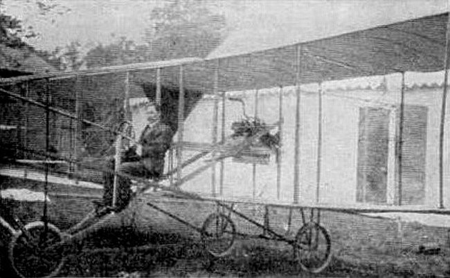
The 1909 Brauner and Smith biplane was designed and built by Pincus Brauner and A. J. Smith, who were members of Aeronautic Society of New York, Morris Park. Their biplane was the second aircraft of the Society to fly. Both Brauner and Smith made numerous flights in the machine proving its airworthiness. Later, the aircraft was exhibited at Madison Square Garden. Eventually Brauner, while attempting to reach a greater height, raised his front control too acutely, and fell backwards, almost totally destroying the machine, but he escaped unhurt.

Bratukhin B-11

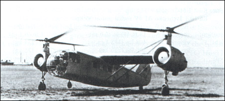
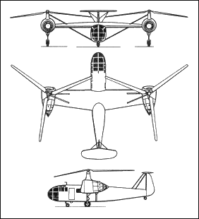
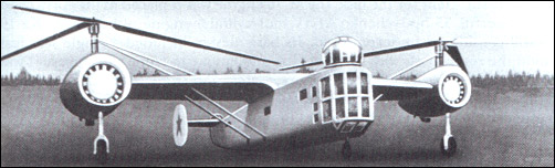
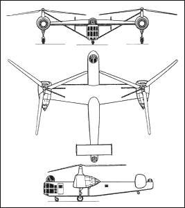
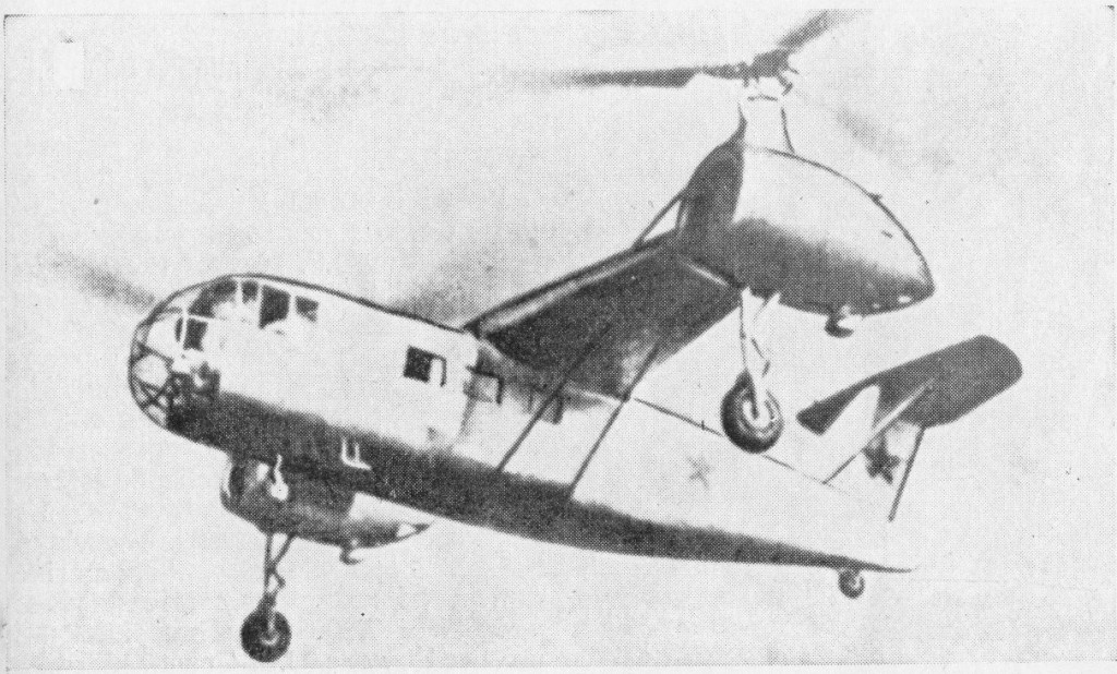
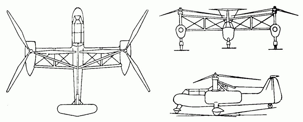
The last design authorised from OKB-3 was to provide comparision against Mil and Yak single-rotor submissions to VVS requirement for a three-seat all-weather communications helicopter. Dynamic parts were as previous Bratukhin except for hydraulic rotor-hub dampers and faired masts with oil-cooler inlets. Wing of lifting section are set at zero incidence. The fuselage had improved form, with round instead of polyhedral top and bottom. The tail was basically as the B-5. The pilot was in B-5 type nose, main cabin for two seats, with space at rear for freight ot two stretchers (in lieu of passengers) loaded through enlarged door. Improved differential rotor controls with reduced friction were fitted. The B-11 was equipped for blind flight.
Two prototypes were completed in April 1948, flying in June and September. Progress was made with measured performance, sustained (47 min) single-engine flight, autorotative landings and in eradication of various faults stemming mainly from vibration was achieved. One problem was lack of wing lift resulting from incidence setting, causing the rotors to stall at high forward speeds. A further snag was hydraulic leaks difficult to rectify. On 13 Decemeber 1948 first machine shed a blade from the right rotor, killing Ponomaryov and I.G.Nilus.
After several modification, including installation of new engines (same series), it was presented on an Aviation Parade.
The favored scheme of twin-rotor helicopter became “The Flying Banana” (due to less drag), and the transversal scheme was not used again until the Mil Mi-12.

B-11
Engine: 2 x AI-26GRF, 575hp
Rotor diameter: 10.0m
Take-off weight: 4150kg
Empty weight: 3398kg
Max speed: 155km/h
Service ceiling: 2550m
Range: 328km
Crew: 3
Passengers: 1-3

Bratukhin B-10

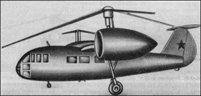
Also designated VNP (Vozdushni Nabludatyelnii Punkt – aerial observation point), its original role was to replace the AK in artillery spotting. The Bratukhin helicopter had become larger and potentially more capable and the VNP was to be a multi-role machine able to fly recon, tactical supply and even casevac missions. Engines were fully boosted AI-26 version, and dynamic parts were essentially the same as the B-9. Wings were of the same plan and section as the B-9 but with a pair of bracing struts from the bottom of two main-spar frames in the fuselage to the spar booms at 60% semi-span, and two bracing struts from the upper spar booms at same location to the top of rotor masts. The fuselage was an entirely new dural monocoque with a glazed nose seating the pilot on the left and navigator on the right under a large observation dome. An was also in the tail, again with large observation dome. A new tail with a variable-incidence tailplane mounted on the fuselage carrying endplate fins(latter possibly rudders). Usual four-wheel landing gear. The central fuselage was available for additional loads: three passengers, or two stretchers (room for more but weight-limited) or 200kg cargo or various radio or photographic equipment. Entrance door on left.
A single example was built and flown 1947. Behaviour was satisfactory, and complete performance measurements were taken. Later fitted ShKAS at nose and tail. At the time on the ‘decision-making level’ attention was shifted to competing schemes of helicopters (under influence of Western designs). Despite B-10 was performing well, it failed to catch any interest in the ‘High Circles’.
According to Shavrov 1947-48 saw general disillusionment with helicopters and especially with twin lateral rotor configuration.

B-10
Engine: 2 x AI-26GRF, 575hp
Rotor diameter: 10.0m
Take-off weight: 3900kg
Empty weight: 3019kg
Max speed: 218km/h
Service ceiling: 6550m
Hovering ceiling: 2200m
Range: 440km
Crew: 3
Passengers: 2-3

Bratukhin B-5

A scaled-up derivative of the G-4, with slightly more powerful model of same engines.
The first helicopter designated for Bratukhin himself, the transmission and other dynamic parts were identical but the new airframe had a lifting aerofoil wing instead of space-frame outriggers and large passenger fuselage.
Designed as a duralumin semi-monocoque (not steel tube as has been reported) with a level floor and door on the right side. A total of 7 seats, intended as two crew and 5 passenger seats, with an aisle along the right wall. Wings were also of light-alloy stressed-skin construction with lifting profile to carry about 25% of the weight in cruise. Fixed tricycle gear with bumber tail-wheel.
A single example was completed in 1947 powered by supercharged version of the AI-26GR engine, but only limited testing was undertaken because of inadequate wing stiffness.

B-5
Engines: 2 x AI-26GRF, 550hp
Rotor diameter: 10.0m
Take-off weight: 4032kg
Empty weight: 2932kg
Max speed: 236km/h
Service ceiling: 6400m
Hovering ceiling: 2280m
Range: 595km
Crew: 2
Passengers: 5

Bratukhin G-4

The first Soviet helicopter with the engines purposely designed, with cooling fan and front gearbox giving vertical and lateral outputs for the rotor and for transverse coupling shaft. The transmission was provided with centrifugal clutch; overall drive ratio 0.27 (540 rotor rpm). The main rotor had an inbuilt twist of 6 deg 45 min along the blade, and blade spar were extruded instead of folded sheet. Two prototypes were built, the first flown in October 1947 by M.K.Baikalov and second a month later. In January 1948 the first G-4 was damaged in the course of autorotational descents and deadstick landings typically at 12 m/s descent along 15.5-16 deg glide path.
The first prototype did not meet expectations (some calculated parameters were not reached). The second prototype had an improved rotor blade airfoil passed the extended test program without problems. Gliding (autorotation) rate was 12m/s, with gliding angle 16°. In this case landing speed was 80-90km/h with 10-15m roll.
The second G-4 was the first helicopter in the Soviet Union to meet its stipulated life for dynamic parts (in this case 100h). A small series constructed 1947-48, according to one account four flying out of ten ordered.
A G-4 and two G-3s participated in Aviation Parade in 1947.

G-4
Engine: 2 x AI-26GR pistone engine, 370kW
Rotor diameter: 7.7m
Take-off weight: 3002kg
Empty weight: 2364kg
Max speed: 148km/h
Ceiling: 2400m
Range: 233km
Crew: 1

Bratukhin G-3 / AK          

The third Bratukhin helicopter was based on the Omega / G-2 but planned from outset for operational use by VVS as AK (Artilleriiskii Korrektirovshchik – artillery correction). There were no significant differences apart from more powerful, imported, engines. Two prototypes ordered in 1944 and first flown in 1945. On completion of State trials in 1945, a batch of ten AKs were ordered. Soviet histories mention only original two prototypes as having flown. A single AK delivered to VVS with dual control for training helicopter pilots.

Bratukhin Omega / 2MG / Omega II / G-2

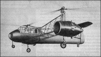
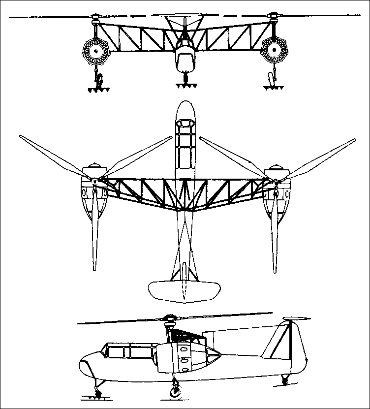
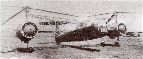
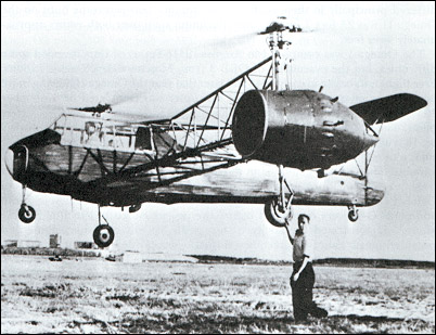
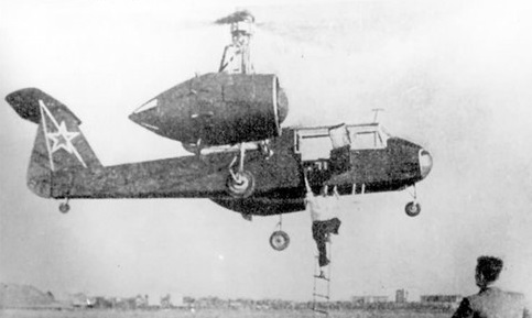
Also designated 2MG (twin-engined helicopter), the Omega project was authorised on 27 June 1940 with two engine rotor groups side-by-side and steel-tube construction with fabric covering. Lateral structures carrying engine rotor units and fixed main landing gears were triangular spaceframes with two lower booms and one at top, with no covering. Fully articulated hubs of steel and light-alloy, carrying three duralumin blades, rotors being handed to rotate in opposite directions. Each rotor was driven by separate MV-6 engine linked with synchronizing shaft with universal joint on aircraft centreline. This shaft provided also opportunity to fly helicopter with any one of engines running. Engines of Omega were equipped with specially designed gearboxes, clutch and other elements. Manual controls, driving swash-plates in fixed and rotating parts of head for collective and cyclic pitch control. Much research into optimum method with differential collective to apply initial bank and then T-tail rudder, worked by pedals, to make turns. Emergency control for immediately autorotative setting of both rotors. Final 0.231 gearbox to rotors (577 rpm). No centrifugal clutches. Three mechanical clutches, with overrunning capability, engaged by observer after both engines were running. First drive to associated rotor was clutched-in; then interlink left/right shaft. Fuel tanks behind engines. Observer behind pilot.

The helicopter was ready for testing in August 1941, thr final design having no wheel or rotor brakes but trimming tailplane with pilot handwheel. Tentative hovering tests, interrupted by engine rough running and overheating. Six-month delay followed the evacuation of the OKB-3 in October 1941. Pilot K.I.Ponomaryov gradually made progress in 1942, discovering structural and control problems but remained tethered until early 1943. The engines seriously overheated.

The Omega II, sometimes called G-2 (helicopter 2), was the original design with superior engines in streamlined pods with fan-assisted cooling. Gearboxes, clutches, cooling system etc were redesigned. Drive ratio 0.32. Important progress was made in optimization of gearbox ratio. It resulted in increase of the rotor lift force by 300kg and substantial increase of ceiling.

Rotor masts and outriggers stiffened, and dynamic parts (cliutches and gearboxes) redesigned for a longer life. Test flown by Ponomaryov in September 1944 with good results, but damaged in January 1945, repaired and improved (drive ratio 0.283) and used again from July 1945, by this time for research and pilot training. With chief engineer D.T.Matsitskii as observer, gained a height of 3km. Demonstrated in Tushino by M.K.Baikalov in August 1946.

Omega II

The Omega II performed in the 1948 Soviet Aviation Day Display at Tushino.

Omega
Engine: 2 x MV-6 piston engine, 220hp
Rotor diameter: 7.0m
Length: 8.2m
Width with rotors turning: 14.2m
Take-off weight: 2050kg
Empty weight: 1760kg
Max speed: 186km/h
Service ceiling: 700m
Hovering ceiling: 290m
Range: 250km
Crew: 1

Omega II
Engine: 2×750 h.p. Ash-21
Rotors: 2 x 3-blade main rotors on outriggers.
Seats: 8

Brantly-Hynes 305 / H-5

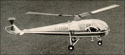
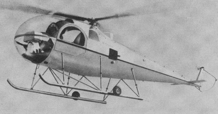
Brantly produced an enlarged B-2, named the Model 305 which had a longer forward fuselage providing a rear 3-passenger bench seat. The new five seater (N2200U) made its first flight in January 1964, powered by a 305hp Lycoming IVO-540-A1A engine and received its type certificate on 29 July 1965. The cabin has two bucket seats forward, seating for three aft, capacity for 200 lb of baggage, can fly 120 mph and sold for $48,900.

Brantly immediately commenced production but the Model 305 suffered from persistent ground resonance problems and they only built 45 examples.

It differs from the B2B externally by having a small variable-incidence tail-plane, and an enlarged cabin accommodates a total of five persons on two side-by-side forward seats, and an aft bench seat for three.
The rotor system and airframe was the same as the B-2B, but enlarged and conventional direct mechanical flying controls.

The landing gear was a choice of skid, wheel or float gear. Skid type has four oleo struts, two on each side, and small retractable ground handling wheels. Wheel gear has single mainwheels and twin nosewheels, all with oleo-pneumatic shock-absorbers of Brantly manufacture. Goodyear mainwheels and tyres size 5.00-5, pressure 1.93 bars. Goodyear single-disc hydraulic brakes on mainwheels.

The 227.4kW Textron Lycoming IVO-540-B1A flat-six engine, was mounted vertically, with dual cooling fans. One rubber fuel cell under engine, capacity 163 litres. Refuelling point in port side of fuselage. Oil capacity 9.5 litres.

A rear compartment for 113kg of baggage, with downward hinged door on starboard side.

Model 305

44 were built during the 1960s and another four built by Hynes Aviation in 1985 as the H-5. Michael K. Hynes, owner of the type certificates, established Brantly-Hynes Helicopter Inc. on 1 January 1975, initially to provide product support for the large number of Brantly helicopters in use. He subsequently started up a production line for the B-2B, and also the larger Model 305.

Improved prototype with redesigned rotor head and new blade aerofoil completed about 30 hours flying by mid-January 1990. New main rotor bearing fitted. Cabin streamlined. New production was to begin 1993, but none built.

Engines: Lycoming IVO-540-B1A, 305 hp, 227kW
Main rotor diameter: 8.74m
Fuselage length: 7.44m
Height: 2.44m
Disc loading: 4.5 lb/sq.ft.
Pwr loading: 9.5 lb/hp.
Max TO wt: 1315kg, 2900 lb.
Empty wt: 816kg, 1732 lb.
Equipped useful load: 1106 lb.
Payload max fuel: 854 lb.
Range max fuel/ cruise: 199 nm/ 1.9 hr.
Range max fuel and payload: 354km
Service ceiling: 3660m, 11,000 ft.
Max speed: 193km/h
Max cruise: 177km/h, 104 kt.
Max range cruise: 95 kt.
ROC: 975 fpm.
HIGE: 4000 ft.
HOGE: 1500 ft.
Max sling load: 800 lb.
Fuel cap: 252 lb.
Seats: 5.