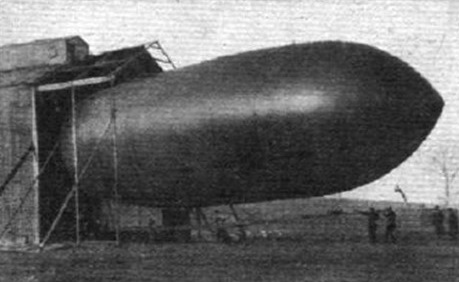
During 1911 Willows moved his business from Cardiff to Birmingham, from where the Willows No.4 was launched in June 1912. The completed ship being 110 ft in length with a 24,000 cu.ft capacity envelope of oiled cotton, carrying a small car mounted on a long boom containing the crew of two or three and a 35 hp Anzani engine driving swivelling airscrews. Simple cruciform fin and rudder planes were affixed to the rear of the envelope.
This airship was inspected and appraised by the newly formed Royal Flying Corps and the navy, where the quality of workmanship involved in its construction was praised and the craft adjudged to be suitable for traing purposes for the two services. In July 1912 the Willows No.4 was purchased by the Admiralty and after modification, which included the fitting of new envelope, she became naval airship HMA No.2. Willows built several other airships including a further order for the navy. This was to become the prototypr for the early Sea Scout class of airship used for convey protection during the war.
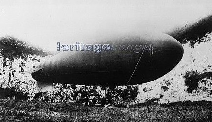
On August 19, 1913, “Naval Airship No.2” (the re-constructed “Willows No.4” – under the command of Lieut. Neville Usborne, R.N.) experienced engine failure due to a broken crankshaft near Odiham in Hampshire. In order to save the hydrogen in the disabled airship, it was decided to try and tow it home employing the airship “Eta” – newly-constructed by the Royal Aircraft Factory and currently undergoing its acceptance trials. Accordingly, a tow-line was attached and the two airships ascended, the “Eta” keeping about 600 feet above the towed ship so as to avoid all chances of fouling the rudder gear. The approximate 8-mile trip back to the airfield at Farnborough (the exact distance to the town of Odiham being 7.4 miles) was made at a groundspeed of 25 mph against a 5 mph headwind. The “Eta” was in all probability skippered by Army Capt. Waterlow at the time.
The Willow 3 was the outcome of five years of experimental work on the simple steering mechanism. The elevation of the dirigible is accomplished by the same set of propellers that produce the forward drive, and by this means it is possible to rise in the vertical plane to any desired altitude even with the whole system heavier than air, and also to rise diagonally in any angle between the vertical and horizontal.
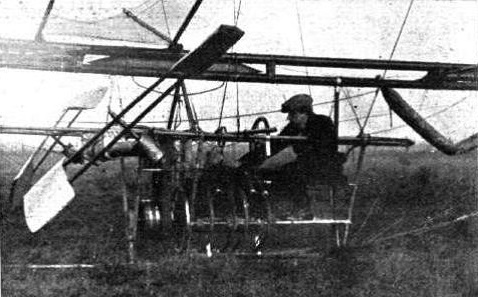
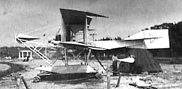
E.T.Willows in the car of his airship
One instance when this direct lift would prove of great value would be in the case of a machine becoming rainsoaked and unable to raise itself by the lifting power of the gas, as occurred at the Crystal Palace when the “Nulli Secundus” was docked there.
In practice the machine is ballasted, so as to have just sufficient buoyancy to lift the 150 ft. trail-rope, and is then driven to the desired altitude, or driven downwards, by the propellers as required.
It has taken some considerable time to perfect this device, because the control of this movement, when applied to a bevel-driven propeller-shaft revolving at high speed, becomes most difficult in practice where ease and quickness of operation are essential.
Other features of this airship are its symmetrical appearance and the ease with which it can be dismantled; in fact it is possible to pack the whole apparatus upon a one-horse trolley for transport.
The system upon which the dirigible has been built is rigid, and quite small, having been constructed for demonstration purposes, it is possible with a few modifications to lay down a dirigible on the same lines of any size.
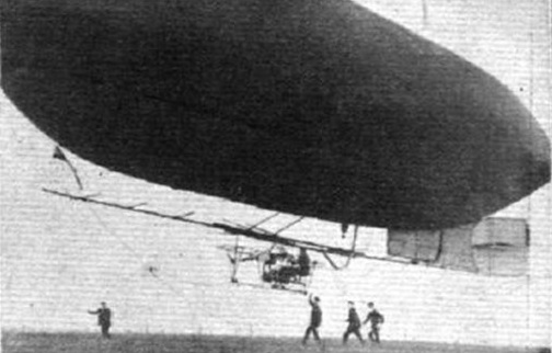
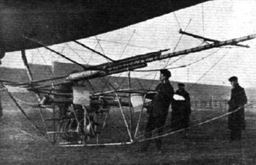
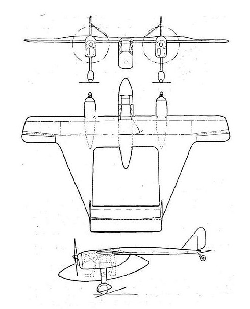
The following are the leading dimensions and details:—Envelope length, 86 ft.; diameter, 22 ft.; fish-shaped, having the greatest diameter about one-third in from the nose, capacity 21,000 cubic ft. The usual valves are fitted; top gas valve, automatic gas and air valves, and ripping panel; a ballonette of one-tenth capacity is placed in centre of lower half of balloon. The suspension is taken by ropes from a canvas band, sewn round the envelope, to a boom 58 ft. in length, built up of 3 in. bamboos and a light 3 in. steel tube.
The car containing the motor, propelling gear, and operator’s seat is hung below the boom by steel cables. A balanced rudder of 56 sq. ft. area is carried at the extremity of the boom also a vertical vane, which has a steadying effect upon the forward motion of the airship. The car is of triangular section and 10 ft. in length, built of steel tube braced with steel wire; the motor, a 30-h.p. 8-cylinder J.A.P., drives a right and left hand propeller placed one on either side of car, through belting and bevel gear.
The propellers are of steel tube with aluminium blades; a guard is fitted to prevent any possibility of damage to the balloon by fracture of a propeller.
The control consists of a steering wheel, which by rotary movement operates the rudder and by a sliding movement alters the position of the propellers for ascending or descending.
A clutch lever and throttle completes the control, so that the machine can be driven single handed, the operator also having the balloon valve lines within reach, which enables a passenger, or for military purposes an observer, to be carried. The weight of the complete car is 550 lbs., the suspension boom 100 lbs., gas-bag 350 lbs. and rudder and vane 21 lbs.
The erecting of the machine and most of the construction has been carried out at Cardiff, the whole of the airship being British built.
The trials which took place during November and December 1909 from the East Moors, Cardiff, were satisfactory in every way, and the airship was overhauled in preparation for some tests of a more severe nature.
The Willows No.3, named City of Cardiff, of 33,000 cu.ft capacity was completed in November 1910 and, with Willows on board, left from Wormwood Scrubs to undertake the first flight from London to Paris, a distance of 218 miles. During this voyage, after a trouble free Channel crossing, a forced landing due to engine trouble necessitated a diversion for repairs. These repairs were carried out at the workshops of Clement-Bayard airship company at Levallois-Peret. After repairs the airship continued to Paris the next day, arriving to much acclaim and earning the distinction of being the first British airship to cross the Channel.
The Willows airships were a series of pioneering non-rigid airships designed and built in Wales by Ernest Thompson Willows. The larger Willows No. 2 first flew on 26 November 1909. It was 86 ft long and 22 ft in diameter with a 29,000 cubic feet (820 m³) volume.
On 4 June 1910 Willows landed the No. 2 outside of Cardiff City Hall and then flew back to his shed at East Moors. On 11 July 1910 it flew from Cheltenham to Cardiff and the following month on 6 August it returned to London. The trip included navigating by night and landing a Crystal Palace at dawn. The 122-mile (196 km) flight was a record for a cross-country flight in Britain and Willows was the first aviator to cross the Bristol Channel in a powered aircraft. No. 2 was powered by a JAP 30 hp air-cooled V8 engine and had two swivelling propellers mounted either side of the suspended car. It was also fitted with a rudder for directional control. After six flights it was rebuilt and lengthened and became No. 3, which was named “City of Cardiff”.
From about 1937, the London-based Willoughby Delta Company was considering the construction of a flying wing airliner. Early in 1939, the Delta 9 was to be a tri-motor monoplane with a span of over 100 ft (30 m) with a thick and wide chord centre section, outboard of which the wing was thicker and much greater in chord, in part forming one of a pair of tail booms that carried the double finned empennage. Its trailing edge was at about 20° to the centre line, continuing forwards then turning through 70° to produce the trailing dge of the outer wing section. This was narrower in chord than the centre section. The Delta 9 was seen as a realistic approximation to a true flying wing, with its advantage of a well-distributed load because of the absence of parts like a fuselage which did not contribute to lift. There was also the intention of producing an aircraft that was essentially stall-free.
The unusual design called for a lot of preparatory wind tunnel work, carried out in the UK at the National Physical Laboratory, the City & Guilds, Farnborough and Queen Mary College, London. Valuable pressure distribution measurements were made in the United States at the Guggenheim Institute of New York University. The results were encouraging, producing for example curves of lift coefficient versus angle of incidence that increased linearly in the normal way and then flattened without the usual decrease in lift associated with the stall. It appeared that, at high speed and low angles the forward part of the wing provided most of the lift, but as the stall approached the rear part contributed more. These results encouraged the company to build the Willoughby Delta 8 to investigate the general aerodynamics of the layout with a smaller aeroplane. The exact name seems to be uncertain: the contemporary (February 1939) Flight article calls it Delta 8, in line with the airliner named as Delta 9, but the registration documents from that January refer to the Delta F and the latter name has been widely used. The design had first been announced in Flight in 1937 as the Delta F. The Delta 8 was not a scale model of the proposed airliner, but the arrangement of its lifting surfaces was similar.
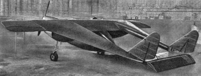
A twin-engined aircraft constructed of wood, the Delta 8 was a twin boom machine. It had a central nacelle, almost elliptical in profile, suspended beneath the wing and containing the glazed cabin. This had tandem seats, accessed via a starboard side door. The wings were built around two conventional transverse spars, unusual only in becoming deeper between the outer boundary of the centre section and the inboard limit of the narrow chord outer sections. The latter carried ailerons over the whole of its trailing edges. The longitudinal spars of the “side wings”, acting as booms, slipped into slots cut into the transverse wing spars. On each side, three longitudinal and very long chord ribs, plus a stiffening diagonal rib that ran to the rear end of the side wing, formed the aerofoil section of these wings. The transverse section of the side wings was also aerofoil shaped, blunt on the inner edge and fine outboard.
Two 125 hp (93 kW) Menasco Pirate C.4 four-cylinder air-cooled inline engines driving two-bladed propellers were mounted against the underside of the wing in steel cradles, at the points where the wing thickness increased. There was a wooden fairing behind, through which ran, to the front spar, the cantilever fixed main undercarriage legs, faired and spatted. The tailplane joined the rearmost inner edges of the side wings, carrying the tailwheel at its centre, and a broad elevator hinged clear of the rest of the structure. Small fins mounted over the tailplane carried balanced rudders, their overall profile almost triangular. The fins were externally braced to the tailplane.
The Delta 9 as described in Flight was expected to carry 36 passengers in two side wing cabins for a gross weight of 38,000 lb on three 1,000 hp engines. The cabins were expected to be have at least a 6 foot headroom but lacked side windows.
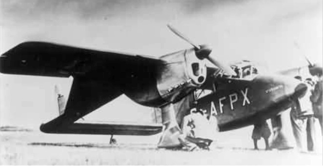
The design was constructed at Minster Lovell between Witney and Burford, and first flew on 11 March 1939 at Witney, registered as G-AFPX and named “St Francis”. On 14 May 1939, piloted by A.N. Kingwill, it was demonstrated at the Royal Aeronautical Society’s garden party fly-in at Great West Aerodrome, also at Heston Aerodrome. On 10 July 1939, it crashed near Bicester, killing the pilot Hugh Olley and the Delta’s designer, Percival Willoughby. The crash was not attributed to the novel configuration but to an ill-designed elevator trim tab that sent the Delta into a dive. With the death of the designer and the coming of war, no more was heard of this type of flying wing.
Delta 8 Engines: 2 × Menasco Pirate C.4, 125 hp (93 kW) Wingspan: 34 ft 6 in (10.52 m) Length: 26 ft 1 in (7.95 m) Empty weight: 1,585 lb (719 kg) Gross weight: 2,350 lb (1,066 kg) Maximum speed: 183 mph (295 km/h; 159 kn) Cruise speed: 165 mph (143 kn; 266 km/h) Stall speed: 60 mph (52 kn; 97 km/h) Range: 340 mi (295 nmi; 547 km) Crew: 2
The Capt Hugh L. Willoughby War-Hawk built circa 1910 was described in Aero 10/14/11: “[Willoughby}, who built the famous War-Hawk, perhaps the largest biplane ever constructed…”
Hugh L. Willoughby (1856-1939) made his first flights in this machine at Atlantic City in the autumn of 1910. The pusher biplane with dart-shaped tail surfaces featured design cues from both Wright and Farman. It was powered by a 30 hp engine built by the Pennsylvania Automobile Co.
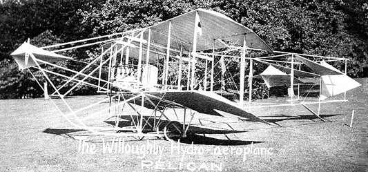
The 1911 Pelican was a single place “modernized” Wright-type hydroaeroplane by Capt Hugh L. Willoughby with a 50hp tractor engine; span: 30’0″. Patented double tails, brass-sheathed twin pontoons, a side-mounted wheel for pitch control, a control column that worked the rudders for yaw, shoulder-operated ailerons, and a spring-mounted pedal accelerator as in an automobile but working in reverse—depress to close the throttle, and foot off for full speed.
Karl Willing’s third monoplane and first Gotha aeroplane. Willing had already built two monoplanes, when in 1912, lacking money for further work, asked for help from the Gothaer Waggonfabrik (Thüringen). This third monoplane was built in the old Gothaer Waggonfabrik shops and was powered by a 70 hp RAW engine. The machine was offered to the army but refused before it was ever flown, and apparently it never was.
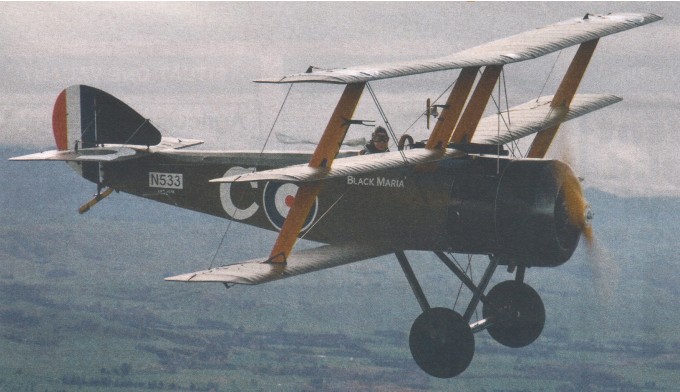
Chad Willie of Corning, Iowa, USA, has built several examples of Sopwith Triplane replicas working from original drawings and dimensions, but incorporating some modern construction techniques including steel tube fuselage, a modern engine, and simplified wing construction.
The Vintage Aviator Ltd fitted a Russian M-14P direct drive 9 cylinder 220 hp radial and one of its own replica Vickers machine guns. The top speed is about 115 mph and it lands at a comfortable 40 mph.
In 1937 Walt Williams built a two place, open cockpit biplane, N18986, powered by a 36hp Aeronca E-113 engine. It was later repowered with a 40hp Continental A-40.