Winton Grasshopper

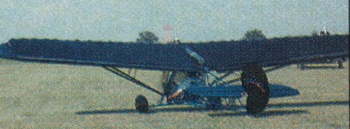
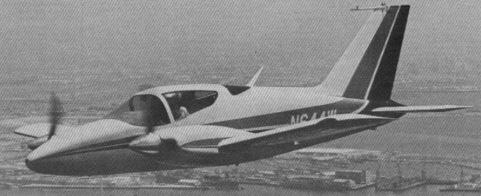
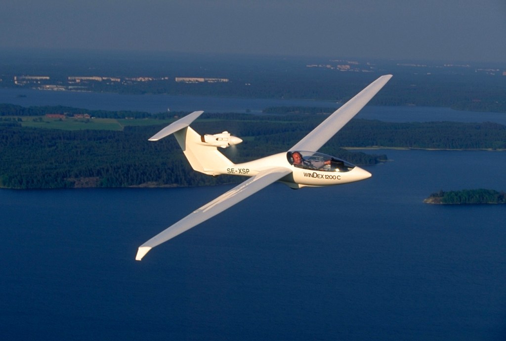
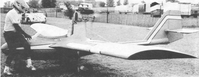
Single seat single engined mid wing mono¬plane with conventional three axis control. Wing has swept back leading and trailing edges, and tapering chord; cruciform tail. Pitch control by fully flying tail; yaw control by fin mounted rudder; control inputs through stick for pitch/roll and pedals for yaw. Wing braced from above by cables; wing profile Karman; 100% double¬ surface. Undercarriage has three wheels in tricycle formation. Push right go right nosewheel steering connected to yaw control. Aluminium tube/glass¬fibre fuselage, partially enclosed. Engine mounted above wing driving pusher propeller.

Col Winton’s Grasshopper won an award for the best foreign ultralight at the 1981 Oshkosh being a sophisti¬cated design, even by 1983 standards. Using Karman aerodynamics for both fuselage and wings, this machine was original¬ly powered by a 432 cc two stroke developing 23 hp. However, following its win at Oshkosh, Pterodactyl Ltd agreed to market the aircraft in the US, using a 30hp Cuyuna, while Col himself had plans to re engine the machine with a 440 cc Robin.

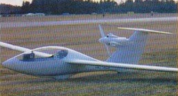
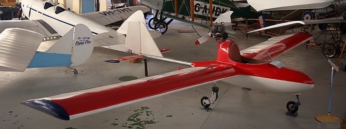
In concept the Grasshopper is a mixture of composite and tube and Dacron construc¬tion. The fuselage is principally made from glass fibre, while the wings are tube and Dacron with glass fibre leading edges and tips. Wings can be removed for transport and storage. The undercarriage has suspension on all three wheels and sometimes wheel spats are fitted.

Tolhurst purchased the moulds and rights from Colin Winton and produced an updated model at Camden, Sydney, Australia.

In 1978 the aircraft was purchased by Mr Juan Humberto Burnett of Perth and used for recreational flying mainly in the Rockingham area from 1978 to 1979. During this time, Burnett made a forced landing on a dry saltlake at Rockingham, due to a blocked fuel line.

Burnett moved to Mt Newman in 1979, and made several long distance flights from that town. One such flight was to Lake Disappointment and return (during which extra fuel was carried), and another flight was made to Port Hedland. The machine crashed on two occasions whilst based at Mt Newman. Once at Newman itself, and once at Marble Bar. In both incidents, damage to the machine was minimal and Burnett was unhurt.

In May 1981 Burnett returned to Perth, and did not get the opportunity to fly the Grasshopper again. The slightly damaged machine was donated to the RAAF Assn. Aviation Museum, where a rebuild was undertaken to bring the machine up to display condition.

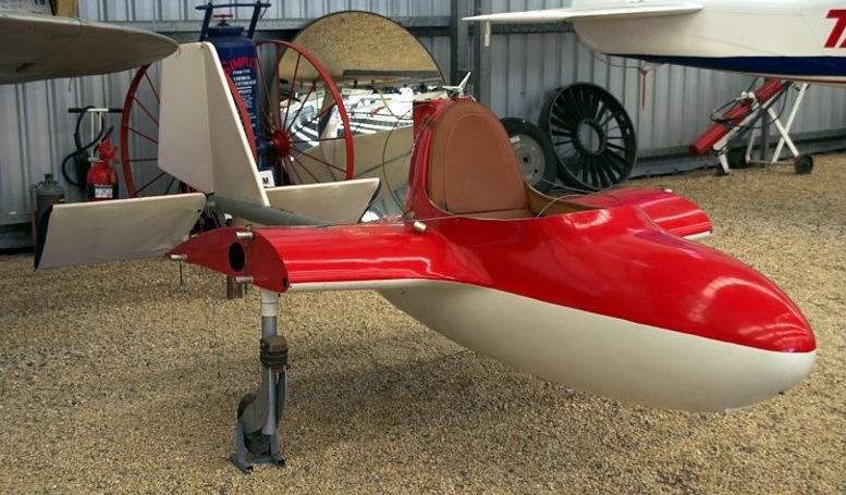
On 25 April 2008 it was purchased from the Aviation Heritage Museum, Bull Creek by Greg Ackman who loaned the aircraft to the Queensland Aviation Museum. On 17 July 2008 it arrived at QAM, Caloundra by road. The aircraft was later donated to QAM.

Have acquired and earlier model grasshopper and am seeking to identify what model and year it was constructed, i also wish to get my hands on a construction manual as i want to restore this aircraft back to its original flying state,
Will White
ima224ru12@yahoo.com.au

Engine: Robin EC44PM
Prop: VAC 36 x 50
Wingspan: 27 ft 11.5 in / 8.52 m
Length: 16 ft 4.75 in / 5.0 m
Empty wt: 122 kg
AUW: 249 kg
Cruise: 60 kts
Max level speed: 75 mph, 120 kph
Initial Climb: 192m/min / 630ft/min
Service Ceiling: 3 962m / 13 000ft
Range: 483km / 300mile

Winstead Special

A one off, the Winstead Special was built by Carl Winstead in 1926, and flown in the Flying Aces Air Circus in the late 1920s. It was a hybrid with a Travel Air fuselage and Swallow wings used for sport racing competition as N2297, piloted by J J Davis. The fuselage is believed to be the steel tube fuselage Walter Beech and Lloyd Stearman built while working for Swallow, but their idea of steel tubing was shot down by Jake Moellendick, president of Swallow at that time. The fuselage was set aside, then sold.

Carl flew it with the Flying Aces Air Circus, Jessie Woods walked its wings. Carl also raced it and barnstormed with it. The next owners, the Marvin Mara family, used it for racing and barnstorming. It changed hands several times until the Davis Family of Ary NB purchased it in 1935 and took it apart for a rework in 1937. It was never reassembled until the remains were found c.1975 in storage and purchased by Paul Dougherty Jr in 1994.

The aircraft was still flying at the Golden Age Air Museum in Bethel, PA, in 2018.

Courtesy David Eckert, Golden Age Air Museum

Engine: Curtiss OX-5, 90h
Wingspan 29’6″
Length: 23’0″
Empty weight: 1281 lb
Gross weight: 1800 lb
Seats: 3

Wings of Freedom Flitplane

A very low cost, tube and fabric ultralight which was available as plans, kit, or ready to fly. The plans did cost US$100, and ready to fly US$10,500.

Doug Widmar / Dwidmar@comcast.net
Jan 2014
I have one and wonder how many are out there and flying. So Far I’ve just got all three wheels off the ground high speed taxi. Ran out of summer 2013. Looking forward to 2014 actually flying it.

Top speed: 63 mph
Cruise: 45 mph
Stall: 27 mph
Range: 120 sm
Rate of climb: 400 fpm
Takeoff dist: 300 ft
Landing dist: 300 ft
Service ceiling: 8000 ft
Engine: 2si (LAPS), 32 hp
HP range: 25-40
Fuel capacity: 5 USG
Empty weight: 245 lb
Gross weight: 500 lb
Height: 5 ft
Length: 15.8 ft
Wing span: 27 ft
Wing area: 145 sq.ft
Seats: 1
Landing gear: tailwheel

Wing D-1 Derringer

By 1962, George Wing had moved on to the development of John Thorp’s little twin, which eventually became the Wing Derringer. George Wing hired John Thorp to design a high performance two seat twin. Thorp, who had been toying with the idea of hanging two engines on his Sky Skooter (one of which Wing owned), was already primed for the idea. They started with a clean sheet of paper and, using two Continental O 200 engines and fixed pitch props, came up with an airplane that was, for its operating costs, a wonderful performer, first built in 1978. John E Robey designed the major assembly tooling for the Wing Derringer at Olin-Dixon in Coffeyville Ks in the late 1960’s. Derringer project leader was Larry Heuberger.

The prototype carried two special Continental 115 hp IO-200 engines with fuel injection. The cowling was 21.5 inches deep. The prototype N3261G first flew on 1 May 1962, kept throwing prop blades, however, its engine out performance was inadequate, and the tweaked engines were not a realistic choice for a production airplane; and so eventually, production prototypes were equipped with 160 hp Lycoming engines. Originally, the Derringer was equipped with very thin, narrow bladed racing props.

While testing the prototype, the next two units were nearing completion in Torrance, California.

The airplane was a compact two-seater with a huge baggage bay behind the seats, a simple rectangular wing and a fuselage that was all curves from nose to tail. Its structure used stretched chem milled skins throughout. With stretch-formed, chemically-etched skins, the number of metal pieces requied is greatly reduced and labour time is cut accordingly. The Derringer has eight fuselage pieces and there isn’t a flat surface on any of them. There are only 13 major skins in the entire plane with the wing a single wrap-around sheet .064 thich where ribs and attachments occur. Remaining metal is etched away to .032 where no stresses occur. The wing walk for instance is .064. Metal skins start out at .064 or .040, depending on their function, and are etched down to whatever thickness the specs call for.

The flight test and production models, under construction in 1964, were to be equipped with 150 hp Lycoming IO-320 engines that operate on 80/87 octane fuel. The production aircraft would have full-feathering, constant speed, two-blade Hartzell props.

Matched-hole tooling means the Derringer can be assembled with a minimum of jigs and fixtures. All holes were to be in a temperature-controlled room so that the parts for number 2 and 3 aircraft were interchangeable with any others, All skin assembly is butt-jointed and flush riveted.

Derringer no.2

The prototype had a fuselage two inches narrower than the production model and was fitted with a slide-back cover. The prototype had a hand brake while the production craft were to have toe brakes. A simple automotive window motor operates the Saginaw ball and screw system for gear retraction and flap movement.

The Derringer undercarriage is fitted with three oleo struts, each with 9 inches of travel.

It would cruise at 190 knots, climbing at 1,700 fpm and boasting a range of over 1,000 nm with reserves.

There is no steering on the ground except with the engines.

Pre-take off check list
Fuel on
Crossfeed off
Trim set
Mixture rich
Flaps 10 deg
Controls free
Canopy locked

Landing check list
Mixture rich
Gear down and locked
Flaps as desired

First deliveries were expected in the Spring of 1964, priced at $27,500.

Wing spent $3 million of his own money, $5 million all told, in developing and certificating the airplane.

Wing contracted with a Kansas manufacturing firm, Olin Dixon, to manufacture an initial production of five with 150hp, ATC A9WE, in 1966, and a second production with 160hp. Problems developed, which Olin blamed on Wing and Wing blamed on Olin. Litigation followed. The first 3 if the initial production were built by Wing’s Transland company

In 1979 Wing Aircraft’s two seat Derringer twin seemed to be on the verge of entering the general aviation marketplace at $40,500. Company President George Wing said that the first production Derringer were to be delivered in the fall. The aircraft, which is powered by two 160 horsepower Lycomings, has a book cruise speed of 182 knots at 65 percent power. Sea level rate of climb is 1,700 feet per minute, and the empty weight is 2,100 pounds. An IFR equipped Derringer was to sell for about $100,000.

Gallery

Prototype
Engine: Continental IO-200, 115 hp
Props: fixed pitch
Wingspan: 29 ft 2 in
Cabin height: 5 ft 7 in
Fin top: 8 ft
Fuel capacity: 2 x 44 USG
Wing loading: 22.15 lb/sq.ft
Liftoff speed: 90 mph
TO roll: 700 ft
Cruise climb: 130 mph / 1200 fpm
UC down max: 125 mph
Stall speed: 66 mph
SE critial speed: 77 mph
Cruise speed 75%: 250mph at 20,000 ft
Baggage compartment: 22 cu.ft
Baggage door is 10×30 in on thebleft side of the fuselage.
Cabin height: 48 in
Cabin width: 44 in
Cabin length: 98 in
Seats: 2
Gear cycling: approx 6 sec

Engine: 2 x Lycoming O-320-B1C, 160 hp
TBO: 2000 hrs
Prop: Hartzell, 2 blade, variable pitch 66 in
Seats: 2
Length: 23 ft
Height: 5.8 ft
Wingspan: 29.1 ft
Wing area: 121 sq.ft
Wing aspect ratio: 7
Max ramp wt: 3050 lbs
Max take off wt: 3050 lb
Standard empty wt: 2100 lb
Max useful load: 950 lb
Max landing wt: 2900 lb
Wing loading: 25.2 lbs/sq.ft
Power loading: 9.5 lbs/hp
Max useable fuel: 522 lb
Climb rate: 1700 fpm @ 104 kt
Climb gradient: 981 ft/nm
Rate of climb @ 8000 ft: 1015 fpm
Service ceiling; 19,600 ft
SE climb rate: 420 fpm @ 96 kts
SE climb gradient: 263 ft/nm
SE ceiling: 8,000 ft
Max speed: 202 kt
Cruise @ 65% power @ 8,000ft: 182 kt
Fuel flow @ 65% power @ 8,000ft: 95 pph
Endurance @ 65% power @ 8,000ft: 5.2 hr
Stalling speed clean: 70 kt
Stall speed gear/flaps down: 63 kt
Turbulent air penetration speed: 148 kt

Windstar YF-80

At Oshkosh 1977, Winstar, of Boise, Idaho, showed a half-scale replica of the Lockheed T-33. This small YF-80 is powered by a Davis cold air jet compressed by a compressor producing 220 lb thrust, driven itself by a V8 motor.

The compressor, designed by Davis, underwent static tests showing that it was possible to obtain 110 Kp at 75% power, consuming less than 65 lt / h.

Wingspan 18’6″
Length: 17’3″
Useful load: 400 lb
Max speed: 300 mph
Stall: 90 mph
Range: 490 mi
Seats: 1

Windex 1200 / AB Radab Windex 1200

In 1980 Sven-Olof Ridder and Harald Undén start a hobby project which was intended to become a very light self-launching glider. During 1983 the Windex wing section developed and tested in wind tunnel. During 1985 Windex 1100 (unpowered) flies and work have started on moulds for powered version with 12 m. span, Windex 1200 C.
In 1986 all Windex 1200 C moulds burn in a factory fire after only 2 sets of laminates have been produced but during 1987 the Windex 1200 C prototype was shown at the Paris Air show.
During 1990 new moulds were being produced for kit production model, Windex 1200 C, fully aerobatic, with carbon fibre spars.
The Windex 1200 C prototype took part in Aerobatic World Championships 1991 for Gliders in Poland. Bronze medal in 2 categories.
10 “pilot-builders” in Sweden and abroad tested kit parts, drawing, manual etc during 1993. During 1992-1995, intensive kit development work, product testing took place with 2 factory prototypes under construction.
The first amateur-constructed kit Windex 1200C flew in 1996.
In 1999 Windexair AB took over the Windex 1200C project from RADAB.

Windex 1200 C is primarily a high-performance sailplane, but has a low-drag fin-mounted engine installation and a variable-pitch propeller turning it into an efficient touring aircraft with a cruising speed of 210 km/h (130 mph) and self-launching capability.
The airframe of Windex 1200 C is stressed for aerobatic manoeuvres and designed to JAR 22 (A). It’s a powered high-performance sailplane that can be easily handled on the ground by one person. Even with engine nacelle, propeller and a 20% smaller span it has a soaring performance equal to or better then a 15-metre Standard Cirrus glider. It also has a climb rate of approximately 2.5 metre/sec (685 fpm), under power.
The specially designed 17% thick airfoil section has comparatively low drag and a wide low drag bucket that is further expanded by a 22.5% chord trailing edge flap. The basic airfoil has very docile stall characteristics in both smooth and rough condition.
The carbon fibre spar has been successfully proof tested at 2175 kgs each side. That gives a useable load factor of +9 g and -7 g (with added safety factor of x 1.725). The König SC-430 3-cylinder engine, used in the Windex 1200C is manufactured in Canada. A displacement of 430 cc gives a take off power of 20 hp at 4200 rpm. Weight of the König engine is 13.8 kg (30.4 lbs). Starting is electric and it uses gasoline of types 100LL, 80UL and mogas98.
The variable-pitch propeller unit for the König engine has been built and
successfully tested to JAR 22 standards. The pilot control pitch from the cockpit, fine pitch to fully feathered.
The JAR tests include 50 hours running and 500 control movements
with engine running. After that the propeller unit is dismantled, searched
for damage, tolerances checked and finally function checked again.
The unit has come through bench testing without problems.

The Windex 1200 C Fuselage kit consist the following:
Laminate parts:
Upper and lower fuselage shells, vertical tail with engine nacelle, left and right, spar for vertical tail, upper and lower stabiliser shells, including spar caps moulded-in, spar web stabiliser, reinforcement module including seat and backrest, cockpit frame left and right, wheel housings for main- and tail wheel fairings, housing, ventilation channel with mechanism mounted, stick mechanism cover, fwd push rod cover aft rudder line covers and rudder pedal assembly.
Plexiglas canopy cut to size with ventilation window (Mecaplex). Main wheel with tire. Tail wheel, complete. Miscellaneous tubing, electrical wiring, switches, fuel lines, etc.
All metal parts are pre made.
All hardware, bolts etc., is AN-quality.
(With a few stainless steel exceptions)
5-Point (aerobatic) harness. Tow hook. Full scale templates for bulkheads, etc. All necessary drawings. Building manual (English language)
Epoxy, fibreglass, adhesives.
NOT INCLUDED: Instrument, paint, abrasive paper and similar materials. Wood, chipboard etc. for building cradle and jigs.
Wing kit
All internal wing fittings, hinges, spoilers, push rods, fuel tanks and wing spars are fitted. Wing is closed to eliminate wing jig and to considerably save building time
Metal parts:
All metal parts are pre-made.
Wing spar pin bolts, bolts for rear and fwd attachment. AN aircraft hardware. Push rods for ailerons and spoiler. 2 x aluminium fuel tanks each 17 litres. Associated couplings and hardware.
All necessary drawings and templates. Building manual. Epoxy, fibreglass, adhesives,
NOT INCLUDED: Paint. Abrasive paper and similar materials. Wood, chipboard etc. for jigs.

The span is 39′ 8″ and best L/D is 38:1. They also offered a fast build kit version for $5l,890 that saves approximately 300 hours from the normal 1000 hour build time. The glider is stressed for aerobatics and has enough fuel capacity and a variable pitch propeller for efficient powered cruising up to 3 hours. The Windex uses preimpregnated composite materials and an autoclave cure process for high strength to weight ratio in the structures. No other current sailplane uses this fairly expensive process. The prize of the kit was US$39,000 in 1997. Windex also offered a building assistance program in Sarasota, Florida for $870 per month and will provide qualified helpers for $40 per hour.

ARACO were the US agents for the Windex.

Windex 1200C
Engine: Konig 2 cycle, 24 hp.
HP range: 18-24.
Wing span: 12.1m / 39.7ft
Wing area: 7.41 sq.m / 79.8 sq.ft
Aspect ratio: 19:8.
Height: 3.7 ft.
Length: 16.1 ft.
Empty Weight: 150 kg/331 lb
Payload: 160 kg/352 lb.
Gross Weight: 310 kg/683 lb
Wing Load: 41.83 kg/sq.m / 8.56 lb/sq.ft
Stall: 45 mph.
Seats: 1
L/D max: 38 at 100 kph / 62 kt / 71 mph
Aspect ratio: 19.75
Min sink: 0.70 m/s / 2.3 fps / 1.36 kt
Airfoil: Radab
Structure: CFRP/GFRP
Load limit: +9/ -6g
Landing gear: fixed single wheel and tail.

AB Radab Windex 1200
Engine: Konig 430, 24 hp
Wing span: 12 m
Wing area: 7.34 sq.m
MAUW: 310 kg
Empty weight: 150 kg
Fuel capacity: 34 lt
Max speed: 240 kph
Cruise speed: 200 kph
Minimum speed: 71 kph
Climb rate: 3 m/s
Seats: 1
Kit price (1998): $39,000

Windspire Aeros

The Aeros is a Single Seat homebuilt helicopter. The plans manual offers pages of highly detailed construction prints, photos and assembly instructions to guide the builder.

This single-seat helicopter can be built in a well-equipped home shop. It features a bolt-together main frame and a standard helicopter control system: full collective with a twist-grip throttle, full cyclic and foot-operated tailrotor pedals. For low-cost and reliability, the drive train utiliizes a converted VW car engine and a primary belt drive that leads to a geared transmission with VW gears. The belt-driven tailrotor is high-mounted to minimize the rolling moment caused by tailrotor thrust. A number of weight-saving features have gone into the design Aeros, including a simple, but attractive monocoque tailboom. The Aeros is licensed as an Experimental Aircraft.
The Guidebook covers, with clear, illustrated explanations, how helicopters work, the various considerations that go into their design, main and tailrotor aerodynamics, control-system operation, and a glossary of terms. Then, fully illustrated with photos and detailed specifications, is a presentation of what is currently available to the helicopter hobbyist in the form of kits and plans. A comprehensive list includes sources of engines, metals, AN hardware, cables, controls, rotorblades, instruments, and the regulations you need to know.

The Aeros is capable of vertical take-offs and landings; hovering; forward, backward and sideward flight. In the event of engine failure, the Aeros can autorotate to a safe landing.

Length: 18 ft.
Height: 7 ft.
Width: 5 ft.
Main rotor dia: 22 ft.
Main rotor chord: 8 in.
Main rotor rpm: 450
Disc loading: 2.5 lb/sq ft
Tail rotor dia.: 40 in.
Tail rotor chord: 3.5 in.
Tail rotor rpm: 3200
Empty weight: 544 lbs.
Useful load: 356 lbs.
Speed (max): 85 mph
Range (max): 65 miles
Engine: Volkswagen
Horsepower: 95+
Power loading: 9 lbs/hp
Fuel capacity: 12 gal.
Fuel consumption: 4 gph
Altitude (max): 12000 ft

Windecker AC-7 Eagle / YE-5 / Composite Aircraft Corporation Eagle

The Windecker Eagle single engine, low wing, four place airplane was built of fiberglass reinforced epoxy and introduced about 1967. The Eagle was fabricated of a resin called “Fibaloy” developed by Dr Leo Windecker, Midland, Texas. It was supposed to make the aeroplane extremely strong, light, easy to manufacture and, because of its rivetless, seamless loveliness, unsurpassedly fast. First flown in 1969, the prototype Eagle (aka X-7) N801WR was lost during spin tests; it wasn’t fast enough and it cost as much as its aluminum competitors.

The Windecler Eagle was certified in 1970 as the first production plastic composite aircraft. Because the FAA was unfamiliar with plastic aircraft t required the Eagle to meet 20 percent higher strength factors than comparable aircraft.

It was not a lack of prospective buyers that sank the Windecker; it was under-capitalization. The cost of getting the Windecker’s foam and fiberglass construction past the FAA is rumored to have been about $20 million; and, although the project started out with generous financing from a large backer, the financing simply stopped, probably because once a certain amount of money has gone down the drain, even an optimistic backer will take flight before sending down even more. Plagued by persistent financial difficulties, the manufacturer, Windecker Industries, was 15 months behind schedule when the first production Eagle emerged from the factory at Midland, Texas. Five airplanes later, the financial ogres halted the program. Production models were Eagle I (aka YE-7) priced at $36,000. Eight were built N801WR-804WR, and N4195G-4198G. NASM has Eagle N4197G s/n 6 at Silver Hill.

Windecker Eagle Prototype N801WR

During the Have Blue era the all composite Windeck Eagle light aircraft was modified and tested by Lockheed for USAF for stealth potential as the YE-5A. A militarised Eagle I c/n 008 (delivered in 1973) as 73-01653, powered by a Continental IO-540G, but the problem of shielding the remaining metal parts (engine, hydraulics, undercarriage) remained, although the YE-5A did contain internal radar absorbent material (RAM) for this purpose.

Jerry Diet¬rick, a Florence, Kentucky mechanical en¬gineer, formed the Composite Aircraft Corporation to acquire the molds, tooling equipment and other assets in 1977 so he could form his own corporation to reopen the factory. Dietrick’s own Eagle, one of the six production aircraft made, un¬derwent detail modifications that would be in¬cluded in future models if the factory reopened.

Composite Aircraft Corp, of Florence, Ken¬tucky, had given details of its plans to produce three derivatives of the all plastics Windecker Eagle, the design and production rights for which were acquired after Windecker Indus¬tries Inc went bankrupt. The four seat high performance Eagle, of glassfibre and epoxy construction, had been certificated by Win¬decker and six examples were built; two of these owned by Jerry Dietrick, president of CAC. The planned developments are Eagle 1, with the same 285 hp Continental IO 520 C engine as the original model but an improved one piece tapered wing with winglets and a single spar in place of the three piece rectangular five spar wing; Eagle 2, combining this new wing with a 317 shp Allison 250 B17C turboprop and Eagle 3, with a new fuselage incorporating a six seat pressurised cabin and turboprop engine. One of the original Eagles was being fitted with an Allison turboprop to help development of the Eagle 2.

The remains of the first two airframes (N801WR and N802WR) are in outdoor storage at KRCK Rockdale HH Coffield Regional Airport, under the stewardship of the local EAA Chapter in 2022. They’re hoping to get these preserved at a museum in Oshkosh. Tail number remains visible on N801WR.

Eagle / Eagle I (A7SW)
Engine: Continental IO-520B, 285hp
Wingspan: 32’0″
Length: 28’5″
Max speed: 220 mph
Cruise speed: 212 mph
Stall: 63 mph
Range: 1100 mi
Ceiling: 18,000′
Seats: 4