Wright R-3350 Duplex-Cyclone / Cyclone 18

In 1927, Wright Aeronautical introduced its famous “Cyclone” engine, which powered a number of designs in the 1930s. After merging with Curtiss to become Curtiss-Wright in 1929, an effort was started to redesign the engine to the 1,000 hp (750 kW) class. The new Wright R-1820 Cyclone 9 first ran successfully in 1935.

In 1935 Wright decided to follow P&W’s lead, and started to develop much larger engines based on the mechanics of the Cyclone. The result were two designs with a somewhat shorter stroke, a 14-cylinder design that would evolve into the Wright R-2600, and a much larger 18-cylinder design that became the R-3350.

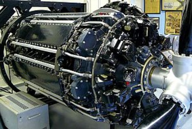
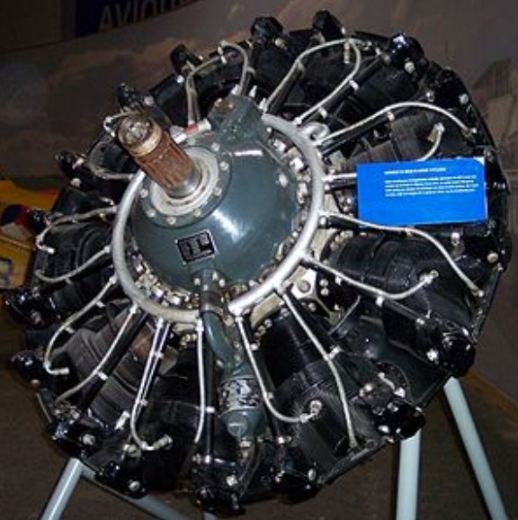
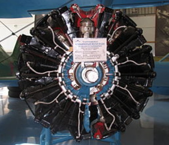
The Wright R-3350 Turbo Compound is an air-cooled, double-row, 18-cylinder, static radial aircraft engine displacing 3,350 in³. Turbo Compounds could produce up to 3,700 take-off horsepower when using fuels available during the zenith of their service history. Cruise fuel consumption could be as low as 0.40 lb/hp/hr.

The goal of high horsepower and excellent fuel efficiency was achieved with the use of a process called turbocompounding, which uses the high velocity exhaust gases to drive a turbine that transfers energy to the crankshaft. Wright was the only aircraft engine manufacturer to put a Turbo Compound engine into production.
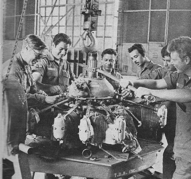
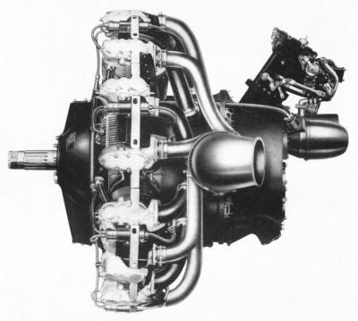
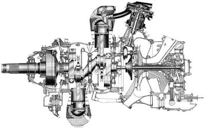
To build an R-3350 Turbo Compound engine, Wright took an improved post-war model engine and sandwiched three power recovery turbines (PRTs) spaced at 120º intervals around the rear of the engine. The addition of the three PRTs between the power and supercharger sections added only eleven extra inches overall length compared to a non-turbocompounded engine. Each PRT is driven the by the exhaust gases of three front- and three rear-row cylinders. The power is transferred to the engine crankshaft through a fluid coupling.
Turbocompounding added about 550 horsepower at take-off power and 240 horsepower at cruise settings over a similar non-turbocompounded R-3350. These power increases were achieved with a weight penalty of about 500 pounds. Operation of the PRTs is fully automatic.

In 1942 Wright started studies on methods of power recovery. A Wright Cyclone nine-cylinder engine fitted with a single PRT was used for initial testing. A final design, sponsored by the U. S. Navy Bureau of Aeronautics, was approved in the summer of 1946. Flight test of the Turbo Compound 18-cylinder engine was made with the test engine installed in the nose of a Boeing B-17. An official 50-hour flight approval test was completed in October 1949. The 150-hour Navy Qualification test was completed in January 1950. The first production Turbo Compound R-3350s were delivered in March 1950. Initially all Turbo Compound R-3350s were for the U. S. Military. Commercial Turbo Compounds were not produced until January 1952.

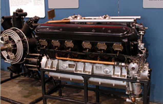
The first R-3350 was run in May 1937. Continued development was slow, both due to the complex nature of the engine, as well as the R-2600 receiving considerably more attention. The R-3350 did not fly until 1941, after the prototype Douglas XB-19 had been redesigned from the Allison V-3420 to the R-3350.

Things changed in 1940 with the introduction of a new contract by the USAAC to develop a long-range bomber capable of flying from the US to Germany with a 20,000 lb (9000 kg) bomb load. Although smaller than the Bomber designs that led to the Douglas XB-19, the new designs required roughly the same amount of power. When preliminary designs were returned in the summer of 1940, three of the four designs were based on the R-3350. Suddenly the engine was seen as the future of army aviation, and serious efforts to get the design into production started. In 1942 Chrysler started the construction of the Dodge Chicago Plant and the new factory, designed by Albert Kahn, was in full operation by early 1944.

By 1943 the new bomber program, the Boeing B-29 Superfortress, was flying. The engines remained temperamental, and showed an alarming tendency for the rear cylinders to overheat, partially due to minimal clearance between the cylinder baffles and the cowl. A number of changes were introduced into the Superfortress’ production line in order to provide more cooling at low speeds, with the aircraft rushed into operational use in the Pacific in 1944. This proved unwise, as the early B-29 tactics of maximum weights, when combined with the high temperatures of the tropical airfields where B-29s were based, produced overheating problems that were not completely solved, and the engines having an additional tendency to swallow their own valves. Because of a high magnesium content in the potentially combustible crankcase alloy, the resulting engine fires — sometimes burning with as high a core temperature approaching 5,600 °F (3,100 °C) from the Duplex Cyclone’s magnesium engine crankcase alloys — were often so intense the main spar could burn through in seconds, resulting in catastrophic wing failure.

Early versions of the R-3350 had carburetors, though the poorly designed elbow entrance to the supercharger led to serious problems with fuel/air distribution. Near the end of WWII, the system was changed to use gasoline direct injection where fuel was injected directly into the combustion chamber. This change improved engine reliability. After the war the engine was redesigned and became a favorite for large aircraft, notably the Lockheed Constellation and Douglas DC-7.

Following the war the Turbo-Compound system was developed to deliver better fuel efficiency. In these versions, three power-recovery turbines (PRT) were inserted into the exhaust piping of each group of six cylinders and geared to the engine crankshaft by fluid couplings to deliver more power. The PRTs recovered about 20 percent of the exhaust energy (around 450 horsepower (340 kW) that would have otherwise been wasted, but reduced engine reliability (Mechanics tended to call them Parts Recovery Turbines, since increased exhaust heat meant a return of the old habit of the engine eating exhaust valves). The fuel burn for the PRT-equipped aircraft was nearly the same as the older Pratt and Whitney R-2800, while producing more useful horsepower. Effective 15 October 1957 a DA-3/DA-4 engine cost $88,200.

Turbo-Cyclone 18

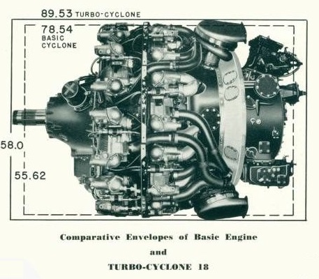
The Wright R3350 Turbo-Cyclone 18 engine had three blow-down turbines connected to the crankshaft through quill shafts, fluid couplings, and gearing form the compounding elements of the turbo-cyclone 18. They fit into the design of the basic eighteen cylinder cyclone to make a compact engine. The mechanism used to connect the turbine to the engine crankshaft is unique and simple. The turbine wheel, mounted on a quill shaft, drives a fluid coupling. The fluid coupling keeps the turbine under load at all times, controls turbine speeds, eliminates the need of synchronizing engine and turbine speed and effectively isolates the turbine and shafting from vibratory forces, the fluid coupling also permits the engine to accelerate and function in a perfectly conventional manner.

By this point reliability had improved with the mean time between overhauls at 3,500 hours and specific fuel consumption in the order of 0.4 lb/hp/hour (243 g/kWh, giving it a 34% fuel efficiency). Engines in use now are limited to 52 inHg (180 kPa) manifold pressure, being 2,880 horsepower (2,150 kW) with 100/130 octane fuel (or 100LL) instead of the 59.5 inHg (201 kPa) and 3,400 horsepower (2,500 kW) possible with 115/145, or better, octane fuels, which are no longer available since many formulations are toxic.

Wright R-3350 Turbo Compound engines are designated first by a 3-digit specification number, followed by “TC18” and ending with a series designation. As an example, the first commercial production Turbo Compound R-3350 was designated 972TC18DA1. Military Turbo Compound engines were given two designations: a military one and WADs specification number. The first production military Turbo Compound engine can be referred to either as an “R-3350-3OW” or an “856TC18DA1.” “TC18” is also a term used when referring to Wright Turbo Compound R-3350s.

Dry weights of TC18s ranged between 3,445 and 3,775 lb depending on the model. The late model TC18EAs were the heaviest. Length of those engines is 89.5” and the diameter measures 56.6”.

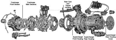
The main body of a TC18 engine is composed of multiple machined sections bolted together. These sections starting from the front of the engine to its rear are: The crankcase front section, crankcase main sections, rear cam and tappet housing, supercharger front and rear housing, and supercharger rear housing cover.

The main crankcase sections, which house the crankshaft and the cylinders, are machined from steel forgings. The remaining engine sections are machined from magnesium alloy castings.
The front crankcase section is sometimes referred to as the “nose case.” Among other components, the nose case contains the 4.5” diameter S.A.E. #60 propeller shaft. The shaft rides in two rolling element bearings. A ball bearing takes the thrust loads and a roller bearing the radial loads. The crankshaft rpm is reduced by a planetary gear reduction assembly located in the nose case. This reduction ratio is 0.4375:1; for every 16 revolutions of the crankshaft, the propeller shaft turns 7 revolutions.

One model of TC18EAs, used in the Lockheed Constellation 1649 Starliners, employed a reduction ratio of 0.355:1. Only 283 of these engines were produced.

TC-18 Longitudinal Cross Section

Other components located inside the nose case are the front cam and balance weight mechanisms. The cam ring contains two tracks, one for the intake valves and one for the exhaust valves. Each track contains four lobes and rotates at 1/8 crankshaft speed. Also contained inside the nose case are nine intake and nine exhaust valve tappets. A counterbalance weight rotating at twice the crankshaft speed is also installed in the nose case. The counterbalance weight is necessary to help negate second-order vibrations. A device called a “torque meter” is enclosed inside the nose case. A torquemeter is a useful tool for in-flight engine management, giving a true indication of available horsepower at the propeller shaft.

Two low-tension ignition distributors are mounted externally on the nose case. These are located at the approximate position of 10:00 and 2:00 o’clock. At the 12:00 o’clock position is the pad to mount a propeller governor. Directly in front of the governor mounting pad is a provision to mount a hoisting eye.

The front oil sump assembly is attached at the 6:00 o’clock position on the nose case. Two pumps are located in the front sump. The smaller of the two pumps scavenges oil from lower cylinder Nos. 8-12 via a rocker box drain manifold and rocker box drain tube. The larger front sump pump collects scavenge oil from the front and front main section and along with the oil collected by the smaller oil pump sends it via an external line to the rear sump. A third pump located in the rear sump returns the oil to the oil tank.

The crankcase main section is composed of four forged and machined steel elements bolted together: the front, center front half, center rear half and rear. The center line of the cylinder rows form parting lines between front and center front, and center rear half and rear parts of the crankcase sections.

The crankshaft is constructed of three pieces. A two-throw center section accommodates the front and rear plain bearing master rods. The link rods are attached to their respective master rods by knuckle pins. The crankshaft throws are 180º apart and have a 6.312” stroke. The front and rear crank webs are clamped to the crank center section with clamp screws.

The master rods and link rods are of the I-beam type of construction rather than the more common H-beam type. Each crankshaft web has a two-piece bronze dynamic counterweight riding on floating pins. The purpose of these counterweights is to offset the rotating and reciprocating mass of connecting rod assemblies and pistons. The mounting via floating pins produces a tuned vibration absorber that reduces crankshaft torsional vibration. The crankshaft assembly rides in three roller bearings. The front crankshaft extension has external splines and a retaining nut and meshes with the propeller reduction drive gear. The rear crankshaft extension is internally splined and coupled to the crankshaft driven gear which receives power from the PRTs.

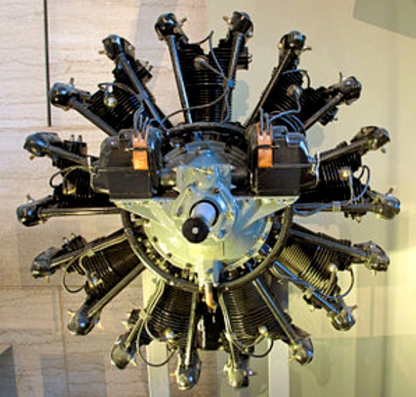
Cylinders are numbered viewing the engine from the rear. Number one is the top-most cylinder of the rear row. Number two cylinder is to the right of number one cylinder and is in the front row. The numbering continues clockwise around the engine with odd numbers being rear row cylinders and even numbers being front row cylinders. Master rods are located in cylinders one and two. The firing order of the engine is 1 – 12 – 5 – 16 – 9 – 2 – 13 – 6 – 17 – 10 – 3 – 14 – 7 – 18 – 11 – 4 – 15 – 8.

TC-18 Exploded View

Each cylinder assembly weighs 55 lb and is attached to the crankcase with 21 cap screws. The cylinder is generic aircraft air cooled construction with a steel barrel threaded in an aluminum head. The cylinder bore is 6.125”. The barrel has replaceable aluminum cooling fins. The forged aluminum head has machined fins. Front and rear row cylinders are not interchangeable; front row cylinder push rods face forward while rear row pushrods face aft.
Two stainless steel inserts are screwed into the front and rear of the head for the spark plugs. A brass insert is screwed into the front of the head to install a fuel injection nozzle. These inserts are secured in the head with a pin driven through the insert and head. On the rear of the cylinder head, slightly below the spark plug hole is an adapter for a thermocouple.

The forged aluminum pistons have five ring grooves with one of the grooves located below the piston pin hole. The pistons are unique in that the piston pin can only be inserted from one side. Once inserted the piston pin is stopped by a shoulder machined in the piston pin bore. Only one piston pin retaining plug is then required per piston.
The rear cam and tappet housing is attached to the crankcase rear section and houses a cam ring for the rear cylinder row along with a rear second-order counterbalance.

The front supercharger housing is attached to the rear cam and tappet housing. Three mounting bosses are provided for the PRTs and nine induction tubes emanate from the front supercharger housing. Each induction tube is branched and feeds a front- and rear-row cylinder. Pressurizing these nine induction tubes is an engine driven supercharger with a 13.5” diameter impeller housed in the supercharger front housing and driven by a primary and secondary planetary gear train. This gear train gives the flight engineer a choice of two speeds to drive the supercharger impeller. Low blower speed drives the supercharger impeller at 6.45 times the crankshaft rpm; high blower speed is 8.67 times the crankshaft rpm. Generally the engine remain in low blower drive unless the aircraft is operated at altitudes above 12,000 feet. At higher altitudes high blower is selected. Mounted on the top of the supercharge rear housing is either a fuel injection metering unit or an injection carburetor The military generally preferred an injection carburetor over a direct cylinder fuel injection system. Military engines had installed either a Ceco (Chandler Evans) 58CD-11 or Bendix Stromberg PR-58TI carburetor.

An injection carburetor introduces metered fuel into the supercharger impeller where it is mixed with air and forced into the cylinders. The direct cylinder fuel injection system has more parts and is more complicated than an injection carburetor.

The direct cylinder fuel injection system employed by some TC18s consists of a master control, two injection pumps, 18 fuel injection lines and 18 individual discharge nozzles. The master control, a Bendix PR-58-52, uses the same mounting pad as an injection carburetor. The master control delivers metered fuel to the two injection pumps. The two injection pumps are mounted on each side of the supercharger rear housing. The right pump supplies the front bank cylinders. The left pump supplies the rear bank cylinders. The Bendix D9H1 injection pumps inject fuel at 500 psi during each cylinders intake stroke.

If the engine was equipped with anti-detonation injection (A.D.I.) the water pump, water regulator and injection lines were located in the area of the master control or injection carburetor. The A.D.I. fluid was injected into the engine right below the carburetor or master control.

The rear oil sump is located on the bottom of the supercharger rear housing. This rear oil sump contains two oil pumps. The rear scavenge pump collects oil from the engines rear section and from the front scavenge pump and returns this oil to an external oil tank. The pressure pump takes oil from the oil tank and sends oil throughout the engine to lubricate and cool internal engine components. A pressure relief valve regulates this oil to 70 ± 5 psi during cruise and high power settings. Both front and rear oil sumps have magnetic drain plugs and removable oil strainers. A check valve at the inlet side of the rear sump prevents the flow of oil under gravity pressure from the external oil tank when the engine is not running.

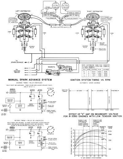
The supercharger rear cover is secured to the supercharger rear housing with a ring of studs and nuts around its outer circumference. Provisions for various accessory drives are located on the supercharger rear cover. Examples of these driven accessories are fuel pumps, hydraulic pumps, cabin superchargers, electrical generators and tachometer generators. The engine starter is located in the center of the supercharge rear cover. The Bendix Scintilla DLN-9 magneto is mounted on the top center portion of the supercharger rear cover. The magneto driven at 9/8 times crankshaft speed is one part of low-tension high-altitude ignition system. Other ignition components are an electrical conduit from the magneto to the two nose case mounted distributors.

The left distributor fires the rear spark plugs in each cylinder, whereas the right distributor fires the front spark plugs. Low voltage current is transmitted from the distributors to the cylinder head mounted step-up transformers. The step-up transformers raise the voltage to a level that will jump the spark plug gap.

Design of the low-tension ignition system features fully redundant electrical paths from a single 9-cylinder dual magneto. Spark advance was eventually removed from all models.

ADs are notifications to owners and operators of certified aircraft that there is a known safety problem with a particular model of aircraft or engine. The Federal Aviation Administration (FAA) and its predecessor agencies issue ADs. The FAA was created in 1958. Compliance with ADs is mandatory. A search of the FAA web site found eight ADs pertaining to TC18s. These were issued between 1954 and 1960.

AD 54-25-02 applied to Wright models 975C18CBI, 972TC18DA1 and 972 TC18DA2. This AD required replacement of three of the intermediate cam drive gears for the front cam drive train. The replacement drive gears incorporated increased tooth width and thicker hubs. Compliance required by November 1, 1955 and at next and each subsequent overhaul. WAD service bulletins C18C-83 and TC18 -92 also addressed this issue.

AD 57-06-04 was the result of an in-flight incident of a 972TC18DA/2 powered Douglas DC-7. On March 5, 1957, American Airlines Flight 87 made an emergency landing at Memphis, Tennessee when number one engine lost its nose section and propeller. This AD mandated at the next engine overhaul the engine front section must be assembled with the propeller shaft thrust bearing (ball bearing) behind the radial bearing (roller bearing) as viewed from the propeller end of the engine. This AD applied to all C18CA, C18CB, TC18DA and TC18EA series engines. WAD service bulletins numbers C18C-252, TC18D-255 and TC-18E66 cover this same subject.

ADs 57-08-07 (which superseded AD 57-01-03) and 57-24-01 applied to all TC18DA and TC18EA series engines. These ADs addressed issue with the impeller drive gear assemblies. If the impeller drive gears fail during flight, all power is lost from that engine.

AD 58-13-05 issued June 30, 1958 addressed the problem of cylinder wall scuffing. This AD was based on earlier WAD service bulletins numbers TC18-269B and TC18 E-81B. These ADs advised operators of TC18s to replace the second chrome-plated compression ring with a cast iron ring at overhaul. A Braniff DC-7C that crashed on March 25, 1958 did not have its 988TC18EA1 engine equipped with a second position cast iron ring. Post-accident investigation of the DC-7C revealed that cylinder number 11 of the number 3 engine failed from fatigue approximately 1½ inches above its mounting flange. The failed cylinder showed evidence of scuffing and ladder cracking. Other improvements mandated by this AD concerned cylinder barrel finish, piston ring fit, use of resin graphite coated pistons and valve springs. At the next overhaul TC18EA series engine fuel injection pump timing and fuel line injection line configuration must be in accordance with applicable WAD service bulletins.

AC 59-17-01 pertained to propeller shaft cracking through the hydro-oil holes. This could cause a loss of propeller control. To prevent this type of failure, the wall of the hydro-oil holes must be inspected and shotpeened in accordance with WAD service bulletins Numbers TC-18E-178 or TC18-359.

ADs 60-03-10 and 60-08-05 dealt with the PRTs. Both of these ADs applied to all TC18DA and TC18EA series engines. AD 60-30-10 mandates the incorporation of WAD PIN 14825 valve body in the PRT oil control valve. This action will prevent inadvertent loss of oil from the PRT fluid couplings AD 60-08-05 required several maintenance checks and specific flight operation procedures. Periodic inspections for excessive clearance between various PRT components was required every 100 hours. At the same time, the turbine wheel and turbine shaft nut must be checked for security by attempting to wobble these components by hand. If looseness is detected, it is an indication the shaft or nut has been overheated. AD60-08-05 also mandated that TC18 powered aircraft should not be climbed at air speeds below the all-engine en route climb speed as shown in the FAA approved flight manual. This climb procedure provides an adequate supply of PRT cooling air.

WAD issued at least 23 service bulletins applicable to TC18s, some of which were later incorporated into ADs.

Gallery

Variants:
R-3350-13 : 2,200 shp (1,640 kW)
R-3350-23 : 2,200 shp (1,640 kW)
R-3350-24W : 2,500 shp (1,860 kW)
R-3350-26W : 2,800 shp (2,090 kW)
R-3350-32W : 3,700 shp (2,760 kW)
R-3350-34 : 3,400 shp (2,540 kW)
R-3350-42WA : 3,800 shp (2,830 kW)
R-3350-53 : 2,700 shp (2,010 kW)
R-3350-57 : 2,200 shp (1,640 kW)
R-3350-85 : 2,500 shp (1,860 kW)
R-3350-89A : 3,500 shp (2,610 kW)
R-3350-93W : 3,500 shp (2,610 kW)

Applications:
Beechcraft XA-38 Grizzly
Boeing B-29 Superfortress
Boeing XC-97 Stratofreighter
Boeing XPBB Sea Ranger
Canadair CP-107 Argus
Consolidated B-32 Dominator
Curtiss XBTC-2
Curtiss XF14C
Curtiss XP-62
Douglas A-1 Skyraider
Douglas BTD Destroyer
Douglas DC-7
Douglas XB-19
Douglas XB-31
Fairchild C-119 Flying Boxcar
Fairchild AC-119
Lockheed Constellation
Lockheed L-049 Constellation
Lockheed C-69 Constellation
Lockheed L-649 Constellation
Lockheed L-749 Constellation
Lockheed L-1049 Super Constellation
Lockheed C-121 Constellation
Lockheed R7V-1 Constellation
Lockheed EC-121 Warning Star
Lockheed L-1649A Starliner
Lockheed P-2 Neptune
Lockheed XB-30
Martin JRM Mars
Martin XB-33 Super Marauder
Martin P5M Marlin
Stroukoff YC-134

Specifications:
R-3350-C18-BA
Type: Twin-row 18-cylinder radial engine
Bore: 6.125 in (155.6 mm)
Stroke: 6.312 in (160.2 mm)
Displacement: 3,347 in3 (54.86 L)
Length: 76.26 in (1,930 mm)
Diameter: 55.78 in (1,420 mm)
Dry weight: 2,670 lb (1,212 kg)
Valvetrain: Pushrod, two valves per cylinder
Supercharger: Two-speed single-stage
Fuel system: Chandler-Evans downdraft carburetor
Fuel type: 100/130
Oil system: Dry sump
Cooling system: Air-cooled
Power output: 2,200 hp at 2,800 rpm (takeoff power)
Specific power: 0.66 hp/in³
Compression ratio: 6.85:1
Power-to-weight ratio: 0.82 hp/lb

Wright R-2160 Tornado

The Wright R-2160 Tornado was an experimental 42-cylinder, 7-bank liquid-cooled inline radial aircraft engine. It was proposed in 1940 with 2,350 hp (1,752 kW) for experimental aircraft such as the Republic XP-69.

Type: 7-bank, 42 cylinder inline radial engine. (7-banks with 6 cylinders in each bank)
Bore: 4.25 in (107.9 mm)
Stroke: 3.625 in (92 mm)
Displacement: 2,160 cu.in (35.39 l)
Length: 96 in (2438 mm)
Diameter: 35.5 in (901.6 mm)
Dry weight: 2,400 lb (1088.6 kg)
Valvetrain: Pushrod, two valves per cylinder
Supercharger: 2 x turbosuperchargers
Fuel system: Direct injection
Fuel type: 100/130
Oil system: Dry sump
Cooling system: Liquid cooled
Power output: 2,350 hp (1,752 kW)
Specific power: 1.08 hp/cu.in
Power-to-weight ratio: 0.97 hp/lb

Wright R-1670 Whirlwind

The Wright Whirlwind was a family of air-cooled radial aircraft engines built by Wright Aeronautical (originally an independent company, later a division of Curtiss-Wright). The family began with nine-cylinder engines, and later expanded to include five-cylinder and seven-cylinder varieties. Fourteen-cylinder twin-row versions were also developed, but these were not commercially produced.

The Whirlwind was a direct descendant of the Lawrance J-1, a nine-cylinder air-cooled radial built by the Lawrance Aero Engine Company for the U.S. Navy. Because the Navy was very enthusiastic about air-cooled radials, but was concerned that Lawrance could not produce enough engines for its needs, it forced Wright to purchase the Lawrance company in 1923 and build the J-1 itself. Wright’s J-1 was the first engine in its nine-cylinder R-790 Whirlwind series.

During the mid-1930s, Wright developed two fourteen-cylinder double-row versions of the Whirlwind, the R-1510 of 600 hp (450 kW), and the R-1670 (Introduced 1934, prototype only) of 800 hp (600 kW). These were used in a number of military aircraft prototypes, but neither engine reached the production stage.

R-1670
14-cylinder twin-row radial, 800 hp (600 kW).

Wright R-1510 Whirlwind

During the mid-1930s, Wright also developed two fourteen-cylinder double-row versions of the Whirlwind, the R-1510 (introduced 1933) of 600 hp (450 kW), and the R-1670 of 800 hp (600 kW). These were used in a number of military aircraft prototypes, but neither engine reached the production stage.

R-1510
14-cylinder twin-row radial, 600 hp (450 kW)

Wright R-790 Whirlwind / J-5 Whirlwind

Wright R-790 (J-5 Whirlwind)

The Wright R-790 Whirlwind was a series of nine-cylinder air-cooled radial aircraft engines built by Wright Aeronautical Corporation, with a total displacement of about 790 cu.in (12.9 L) and around 200 hp (150 kW). These engines were the earliest members of the Wright Whirlwind engine family.

The R-790 Whirlwind began as the Lawrance J-1, a nine-cylinder air-cooled radial developed in 1921 by the Lawrance Aero Engine Company for the U.S. Navy. The Navy was very enthusiastic about air-cooled engines, which it felt were better suited for naval use than liquid-cooled ones. But Lawrance was a small company, and the Navy doubted it could produce enough engines for their needs.

Despite urgings from the Navy, the major U.S. aircraft engine makers, Wright and Curtiss, were satisfied with their liquid-cooled engines and showed no interest in building air-cooled ones. Since the Navy was already a major purchaser of Wright engines, it decided to force the issue by suggesting that Wright purchase Lawrance and build the J-1 itself, while informing the company that the Navy would not buy any more of its existing engines or spare parts. In order to keep the Navy’s business, Wright was thus compelled to buy Lawrance in 1923, and the Lawrance J-1 became the Wright J-1.

By the time Lawrance merged with Wright, it had already developed the J-2, a more powerful version of the J-1 with slightly enlarged bore and displacement. However, Lawrance decided the J-1 was large enough, and the J-2 never went into production; only two examples were built.

Over the next two years, Wright gradually refined the J-1 engine, introducing the J-3, J-4, J-4A, and J-4B. The changes improved the engine’s reliability, cooling, and fuel consumption, but the basic design, dimensions, and performance were unaltered.

The J-4 was the first engine to bear the Whirlwind name; previous engines had no name, only a designation.

The J-5 Whirlwind, introduced in 1925, was a complete redesign of the engine which greatly improved its cooling and breathing, further increasing its reliability and reducing its fuel consumption. Among the more visible changes were a much wider separation between the valves, for better cooling airflow, and completely enclosed pushrods and rocker arms, rather than exposed ones as on the earlier engines.
The U.S. government later designated the J-5 Whirlwind as the R-790, but it did not apply this designation to the older engines.

All these engines had a bore of 4.5 in (11.4 cm), a stroke of 5.5 in (14.0 cm), and a displacement of 788 cu.in (12.91 L).

The J-5 was the last of the original nine-cylinder Whirlwinds. In 1928, it was replaced by the seven-cylinder version of the Whirlwind J-6.

Many Whirlwind engines were used in U.S. Navy aircraft, mostly in trainers but also in some ship-based observation and fighter aircraft. As the engines were refined and their reputation for reliability grew, their usage expanded to U.S. Army trainers and a wide range of U.S. civil aircraft, including the earliest versions of the Fokker Trimotor and Ford Trimotor airliners.

The reliability of J-5 Whirlwind engines also led aviators to use them for a number of record-setting distance and endurance flights. The most famous of these is Charles Lindbergh’s solo transatlantic flight from New York City to Paris on May 20–21, 1927, in the Spirit of St. Louis, powered by a single Whirlwind J-5C. During Lindbergh’s flight, the engine ran continuously for 33.5 hours. Lindbergh’s achievement greatly boosted the Whirlwind’s already good reputation.

Some other historic long-duration flights made in aircraft powered by the J-5 Whirlwind:

  • Clarence Chamberlin and Bert Acosta made a record endurance flight of 51 hours, 11 minutes, 25 seconds in a single-engined Wright-Bellanca WB-2 over New York City in April 1927.
  • Chamberlin and Charles Levine flew non-stop from New York City to Eisleben, Germany, in the same Wright-Bellanca on June 4–6, 1927, in a flight lasting 42.5 hours (3,920 mi).
  • The first successful flight from the continental U.S. to Hawaii was made by Albert Hegenberger and Lester Maitland in the Fokker C-2 Bird of Paradise from Oakland, California, to Honolulu, Hawaii, on June 28–29, 1927, lasting 25 hours 50 minutes (2,400 mi).
  • The first flight across the Pacific was made by Sir Charles Kingsford Smith in the Fokker trimotor Southern Cross from Oakland to Brisbane, Australia, with stops in Hawaii and Fiji, from May 31 to June 9, 1928. The leg from Hawaii to Fiji lasted 34.5 hours over 3,100 mi (5,000 km) of open ocean.
  • A record endurance flight of 150 hours, 40 minutes, and 14 seconds was made by U.S. Army fliers in the Fokker C-2A Question Mark over southern California on January 1–7, 1929. Achieved with the help of aerial refueling, this flight only ended when a pushrod failure stopped one of the engines.

Charles L. Lawrance, who developed the original Whirlwind series and became president of Wright, won the 1927 Collier Trophy for his work on air-cooled radial aircraft engines.

The Whirlwind J-5 was also produced under license in Poland by several makers. Among these were Polskie Zakłady Skody, the Polish branch of Škoda Works, which built about 350 to 400 engines from 1929 to 1931, and the Polish firm Avia, which manufactured a further 300 engines from 1935 to 1938. Polish-built J-5s were used in numerous Polish aircraft, mostly in military training, observation, and liaison aircraft.

Variants
J-1: Lawrance J-1 as built by Wright Aeronautical in 1923.
J-3: Wright’s first refined version, 1923.
J-4: Improved version, 1924. First to be named “Whirlwind”.
J-4A, J-4B: Further refinements of J-4.
J-5 (R-790): Complete redesign with improved reliability and performance, 1925.

Applications:
U.S. aircraft-
Boeing NB-1
Buhl-Verville CA-3 Airster (J-4)
Buhl-Verville CA-3A Airster (J-5)
Consolidated NY-1 and NY-2
Consolidated O-17
Consolidated PT-3
Curtiss AT-5 and AT-5A Hawk
Curtiss N2C-1 Fledgling
Fairchild FC-2
Fokker F.VIIA-3m and F.VIIB-3m
Fokker Universal (Model 4)
Ford Trimotor 4-AT-A and -B
Keystone Pronto
Lockheed Vega 1
Naval Aircraft Factory N3N-1 Canary
New Standard D-25
Pitcairn PA-5 Mailwing and PA-6 Super Mailwing
Ryan B-1 Brougham
Spirit of St. Louis
Stearman NS-1
Stearman C2B and C3B
Stinson Detroiter SB-1 and SM-1
Stinson Junior SM-2AB
Texas-Temple Aero C-4
Texas-Temple Commercial Wing
Travel Air 4000
Vought FU
Vought UO
Waco 10-W (ASO) and 10-T (ATO)

Polish aircraft, using Polish-built engines-
Bartel BM-5d
Lublin R-XIII
PWS-18
PWS-26
PZL Ł.2

Specifications:
R-790 Whirlwind J-5
Type: 9-cylinder naturally aspirated air-cooled radial piston engine
Bore: 4.5 in (114 mm)
Stroke: 5.5 in (140 mm)
Displacement: 788 cu in (12.91 L)
Length: 34 to 40 in (86 to 102 cm)
Diameter: 45 in (114 cm)
Dry weight: 520 lb (236 kg)
Valvetrain: 2 valves per cylinder, pushrod-actuated
Fuel type: 50 octane
Power output: 220 hp (164 kW) @ 2000 RPM
Specific power: 0.279 hp/cu-in (12.7 kW/L)
Compression ratio: 5.1:1
Power-to-weight ratio: 0.423 hp/lb (0.696 kW/kg)

Wright J-3 / J-4 Whirwind

Wright J-4B

By the time Lawrance merged with Wright, it had already developed the J-2, a more powerful version of the J-1 with slightly enlarged bore and displacement. However, Lawrance decided the J-1 was large enough, and the J-2 never went into production; only two examples were built.

Over the next two years, Wright gradually refined the J-1 engine, introducing the J-3, J-4, J-4A, and J-4B. The changes improved the engine’s reliability, cooling, and fuel consumption, but the basic design, dimensions, and performance were unaltered.

The J-4 was the first engine to bear the Whirlwind name; previous engines had no name, only a designation.

Wright J-6 Whirlwind 5 / J-6-5 / R-540 / Hispano-Suiza 5Q / Hispano-Wright 5Q

Wright R-540 Whirlwind

The Wright R-540 Whirlwind was a series of five-cylinder air-cooled radial aircraft engines built by the Wright Aeronautical division of Curtiss-Wright. These engines had a displacement of 540 cu.in (8.85 L) and power ratings of around 165-175 hp (123-130 kW). They were the smallest members of the Wright Whirlwind engine family.

Wright introduced the J-6 Whirlwind family in 1928 to replace the nine-cylinder R-790 series. The J-6 family included varieties with five, seven, and nine cylinders. The five-cylinder version was originally known as the J-6 Whirlwind Five, or J-6-5 for short. The U.S. government designated it as the R-540; Wright later adopted this and dropped the J-6 nomenclature.

The R-540 cylinders are of a steel barrel over which an aluminium alloy head is screwed and shrunk. Intake ports are at the rear with exhaust ports on the forward side of cylinder.

The crankcase assembly is composed of four major castings of aluminium alloy. The cam follower housing carrying the tappet guides is cast integral with the main section of the crankcase.

Two-piece single-throw crankshaft with one-piece master rod and “H” section articulated rods.

Aluminium alloy pistons, cross ribbed on under side of head, and fitted with full floating hollow pins held in place by expanding spring wire locks.

Tulip shaped valves, solid stem inlet valves and hollow stem exhaust valves.

Rotary induction system of Wright design, with “pre-heating” device on carburettor. Provision is made for obtaining, at all times, a clean supply of air to the carburettor.

Lubrication system is designed to eliminate all external oil pipes to the engine.

Equipment supplied was air cleaner and heater, nose cowling, complete exhaust manifold, priming pump, ignition switch, tool kit, external oil filter, and instruction book.

Accessories available at extra cost were Ecllipse hand inertia starter, Eclipse generator, Eclipse generator control box, standard steel propeller hub, fuel pump, Eclipse combination hand and electric inertia starter, Eclipse hand starter with booster magneto, Eclipse electric inertia starter, propeller hub for wooden propeller, metal propeller, and hubs for two or three blade props.

Like all the members of the J-6 Whirlwind family, the R-540 had larger cylinders than the R-790. The piston stroke of 5.5 in (14.0 cm) was unchanged, but the cylinder bore was expanded to 5.0 in (12.7 cm) from the R-790’s bore of 4.5 in (11.4 cm). While the R-790 was naturally aspirated, the R-540, like the other J-6 engines, had a gear-driven supercharger to boost its power output.

Wright gradually refined the R-540, using suffix letters to indicate successive versions. For example, the R-540A had 165 hp (123 kW), while the R-540E of 1931 had power boosted to 175 hp (130 kW) thanks to an improved cylinder head design. Wright sometimes named these versions according to their power, e.g. “Whirlwind 165” or “Whirlwind 175”.

Produced from 1929 to 1937, around 500 were built.

The engine was built in Spain as the Hispano-Suiza 5Q or Hispano-Wright 5Q without modification apart from the use of Hispano’s patented nitriding finishing process.

The R-540 was the smallest, least powerful member of the Whirlwind family and was designed for light aircraft. One of the more popular types to use it was the Curtiss Robin, a light civil utility aircraft. A few were also used in prototype military trainer aircraft that were evaluated by the U.S. Army but not put into production.

The R-540 sold well at first, with over 400 engines being built in 1929. However, with the impact of the Great Depression, sales plummeted, and only about 100 further examples were built over the next eight years. Wright finally ceased production of five-cylinder Whirlwinds in 1937, concentrating on larger engines and leaving the market for small radials to companies like Kinner and Warner.

Since R-540 engines were found solely in light aircraft, they weren’t often used for groundbreaking flights. However, there were a couple of noteworthy exceptions which took advantage of the Whirlwind family’s reputation for high reliability. In 1935, the brothers Al and Fred Key set a new flight endurance record of 653 hours, 34 minutes in the Curtiss Robin J-1 Ole Miss, flying over Meridian, Mississippi, from June 4 to July 1. Their plane was refueled and resupplied in flight, and they could perform simple engine maintenance by walking out on a small catwalk extending between the cabin and the engine. Douglas “Wrong-Way” Corrigan’s famous unauthorized transatlantic flight from New York City to Dublin, Ireland on July 17–18, 1938, used a Curtiss Robin with an R-540 built from the parts of two used engines.

Applications:
Curtiss Robin J-1
Kreider-Reisner Challenger C-4C (Fairchild KR-34C)
Spartan C3-165
Stinson Junior SM-2AA and SM-2AB
Travel Air E-4000
Waco BSO

Specifications:

Type: 5 cylinder, air cooled fixed radial
Military Rating: 165 hp at 2000 rpm
Commercial Rating: 165 hp at 2000 rpm
Displacement: 540 cu.in
Compression ratio: 5.1-1
Bore: 5 in
Stroke: 5 1/2 in
Length: 40 5/8 in
Diameter: 45 in
Weight: 370 lb
Fuel consumption: not more than .55 lb/hp/hr
Oil consumption: not more than .035 lb/hp/hr
Lubrication: Pressure pumps
Ignition: Scintilla dual
Carburation: Stromberg, single barrel
Spark plugs: 2 per cylinder
Price: $3000

R-540E
Type: 5-cylinder supercharged air-cooled radial piston engine
Bore: 5.0 in (127 mm)
Stroke: 5.5 in (140 mm)
Displacement: 540 cu in (8.85 L)
Length: 41.1 in (104.4 cm)
Diameter: 45.0 in (114.3 cm)
Dry weight: 420 lb (191 kg)
Valvetrain: 2 valves per cylinder, pushrod-actuated
Supercharger: gear-driven, 7.05:1 impeller gear ratio
Fuel type: 65 octane
Reduction gear: Direct drive
Power output: 175 hp (130 kW) at 2,000 RPM at sea level
Specific power: 0.324 hp/cu-in (14.7 kW/L)
Compression ratio: 5.1:1
Power-to-weight ratio: 0.417 hp/lb (0.685 kW/kg)

Wright Tornado / T-1 / T-2 / T-3 / T-4 / V-1950

Wright T-3

Developed by Wright Aeronautical, on the lines of the Wright-Hisso engines produced during the First World War, using monobloc cylinder blocks and gear driven overhead camshafts. The T-1 of 1921 had a power output of 500 hp (373 kW), and went into production as the T-2 in 1922 with an increase in power to 525 hp (391 kW).

The T-3 was the third in the line of ‘T’ (Tornado) series engines. The T-3 and T-3A appeared from 1923 producing 575 hp (429 kW) with the final development, the T-4, producing 675 hp (503 kW) by December of that year. Wright attempted to build a racing version of the T rated at 700 hp (522 kW) to rival the Curtiss D-12, but this was not pursued.

The Wright T-3 Tornado, also given the USAF designation Wright V-1950.

Applications:
Curtiss CS
Martin SC
Martin T2M
Martin T3M
Wright F2W
Dayton-Wright XO-3

Specifications:
T-3
Type: V-12 aircraft piston engine
Bore: 5.75 in. (146mm)
Stroke: 6.25 in. (158.8mm)
Displacement: 1,947.54 cu in (31.9 L)
Dry weight: 1,000 lb (453.6 kg)
Cooling system: Air-cooled
Power output: 575 hp (429 kW)
Power-to-weight ratio: 0.575 hp/lb (0.95 kW/kg)

Wright R-1820 Cyclone 9 / Curtiss-Wright R-1820 Cyclone / Hispano-Suiza 9V / Shvetsov M-25

Curtiss-Wright R-1820 Cyclone

In 1932, the R-1750 was developed to a capacity of 1823 cu in. This was the F model Cyclone, designated R-1820 Cyclone 9. This engine introduced a forged aluminium crankcase and was developed through the 1930s to reach 890 hp. It used a General Electric supercharger, and Wright concluded that this feature limited the potential power output of the engine.

Wright R-1820 Cyclone, 675 hp

For the next development, the G-Series of 1937, Wright developed its own single-speed supercharger. The G-series was developed to deliver 1200 hp at 2500 rpm and made up the bulk of R-1820 Cyclone production during World War 2. It was installed in the Boeing B-17 Flying Fortress. The final phase of development of the single row radial design was the H-Series at 1350 hp.

In 1949 the Cyclone 9HE weighed less than 1400 lb and delivered nearly 1500 bhp. The first two were delivered to Douglas for installation in the new DC-3 Super. Apart from new engines, the DC-3 Super has a new tail unit and outer-wing panels, a strengthened undercarriage with complete wheel retraction, and re-arranged internal accommodation. The Cyclone 9HE engines would boost speed by 45 mph to 234 mph and maximum loaded weight increase from 25,200 lb to 27,300 lb.

The engine remained in production well into the 1950s.

The R-1820 was built under license by Lycoming, Pratt & Whitney Canada, and also, during World War II, by the Studebaker Corporation. The Soviet Union had purchased a license for the design, and the Shvetsov OKB was formed to produce the engine as the M-25. In Spain the R-1820 was license-built as the Hispano-Suiza 9V or Hispano-Wright 9V.

The Shvetsov M-25 was a licensed production variant of the Wright R-1820-F3. The first M-25s were produced from kits imported from the United States; the main difference between the later M-25 and the R-1820-F3 was the use of metric components. 13,888 M-25s were produced in the USSR at factories in Perm and Kazan. There were a number of sub-variants which differed from the original M-25 in that they had reduction gears, rather than direct drive. Performance was similar to the equivalent Wright engines. The M-25 was later developed into the ASh-62.

The Shvetsov M-25 was a licensed production variant of the Wright R-1820-F3. The first M-25s were produced from kits imported from the United States; the main difference between the later M-25 and the R-1820-F3 was the use of metric components. 13,888 M-25s were produced in the USSR at factories in Perm and Kazan. There were a number of sub-variants which differed from the original M-25 in that they had reduction gears, rather than direct drive. Performance was similar to the equivalent Wright engines. The M-25 was later developed into the ASh-62.

Shvetsov M-25

The R-1820 was built under license by Lycoming, Pratt & Whitney Canada, and also, during World War II, by the Studebaker Corporation. The Soviet Union had purchased a license for the design, and the Shvetsov OKB was formed to produce the engine as the M-25. In Spain the R-1820 was license-built as the Hispano-Suiza 9V or Hispano-Wright 9V.

The R-1820 was at the heart of many famous aircraft including the early Douglas airliners (prototype DC-1, the DC-2, earliest civilian versions of the DC-3, and the limited-production DC-5), B-17 Flying Fortress, and SBD Dauntless bombers, the early versions of the Polikarpov I-16 fighter (as M-25), and the Piasecki H-21 helicopter.

TC9J2, a Turbocompounded R-1820 Offered in the Early 1950s.

The R-1820 also found limited use in armored vehicles in two forms. The G-200 was a nine-cylinder gas-burning radial that developed 900 hp (670 kW) @ 2,300 rpm and powered the M6 Heavy Tank. The Wright RD-1820 was converted to a diesel by Caterpillar Inc. as the D-200 and produced 450 hp (340 kW) @ 2,000 rpm in the M4A6 Sherman.

Variants:
Unit numbers ending in/with W indicate engines fitted with water-methanol emergency power boost system.

R-1820-04
700 hp (522 kW)

R-1820-1
575 hp (429 kW)

R-1820-4
770 hp (574 kW)

R-1820-19
675 hp (503 kW)

R-1820-22
950 hp (708 kW)

R-1820-25
675 hp (503 kW), 750 hp (559 kW), 775 hp (578 kW)

R-1820-32
1,000 hp (750 kW)

XR-1820-32
800 hp (596 kW)

R-1820-33
775 hp (578 kW)

R-1820-34
940 hp (701 kW), 950 hp (708 kW)

R-1820-34A
1,200 hp (895 kW)

R-1820-40
1,100 hp (820 kW), 1,200 hp (895 kW)

R-1820-41
850 hp (634 kW)

R-1820-45
800 hp (596 kW), 930 hp (694 kW)

R-1820-50
850 hp (634 kW)

R-1820-52
1,000 hp (750 kW)

R-1820-53
930 hp (694 kW), 1,000 hp (750 kW)

R-1820-56
1,200 hp (895 kW), 1,350 hp (1,007 kW)

R-1820-57
1,060 hp (790 kW)

R-1820-60
1,200 hp (895 kW)

R-1820-62
1,350 hp (1,007 kW)

R-1820-66
1,200 hp (895 kW), 1,350 hp (1,007 kW)

R-1820-72W
1,350 hp (1,007 kW), 1,425 hp (1,063 kW)

R-1820-74W
1,500 hp (1,118 kW)

R-1820-76A, B, C, D
1,425 hp (1,063 kW)

R-1820-78
700 hp (522 kW)

R-1820-80
700 hp (522 kW), 1,535 hp (1,145 kW)

R-1820-82WA
1,525 hp (1,137 kW)

R-1820-86
1,425 hp (1,063 kW)

R-1820-97
1,200 hp (895 kW), Fitted with turbosupercharger

R-1820-103
1,425 hp (1,063 kW)

SGR-1820-F3
710 hp (529 kW), 720 hp (537 kW)

SGR-1820-F2
720 hp (537 kW)

R-1820-F53
770 hp (574 kW)

R-1820-F56
790 hp (589 kW)

GR-1820-G2
1,000 hp (750 kW)

R-1820-G3
840 hp (626 kW)

R-1820-G5
950 hp (708 kW)

R-1820-G101
1,100 hp (820 kW)

R-1820-G102
775 hp (578 kW)

GR-1820-G102A
1,100 hp (820 kW)

R-1820-G102A
1,100 hp (820 kW)

R-1820-G102A
1,100 hp (820 kW)

R-1820-G202A
1,200 hp (895 kW)

R-1820-G103
1,000 hp (750 kW)

R-1820-G105
1,000 hp (750 kW)

R-1820-G205A
1,200 hp (895 kW)

Hispano-Suiza 9V
Licence built R-1820

Hispano-Suiza 9Vbr
Hispano-Suiza 9Vbs
Hispano-Suiza 9Vd

Shvetsov M-25

Applications
Boeing B-17 Flying Fortress
Boeing 307
Brewster F2A
Curtiss AT-32-A Condor
Curtiss SBC-4 Helldiver
Curtiss P-36 Mohawk
Curtiss SC Seahawk
Curtiss-Wright CW-21
Douglas A-33
Douglas B-18
Douglas DC-2
Douglas DC-3 (DST, G-102 and G-202)
Douglas Super DC-3, R4D-8 / C-117
Douglas DC-5
Douglas SBD Dauntless
FMA AeMB.2 Bombi
General Motors FM-2 Wildcat
Grumman TF-1 / C-1 Trader
Grumman FF-1
Grumman F3F
Grumman HU-16 Albatross
Grumman J2F Duck
Grumman S-2 Tracker
Lockheed 14
Lockheed Lodestar
Lockheed Hudson
Martin B-10
North American NA-44
North American O-47
North American P-64
North American T-28B/C/D Trojan
Northrop YC-125 Raider
Piasecki H-21
Polikarpov I-16
Ryan FR Fireball
Sikorsky S-58/HUS/HSS/H-34

Vehicles:
M4A6 tank
M6 heavy tank

Specifications:

GR-1820-G2
Type: Nine-cylinder single-row supercharged air-cooled radial engine
Bore: 6 1⁄8 in (155.6 mm)
Stroke: 6 7⁄8 in (174.6 mm)
Displacement: 1,823 in³ (29.88 L)
Length: 47.76 in (1,213 mm)
Diameter: 54.25 in (1,378 mm)
Dry weight: 1,184 lb (537 kg)
Valvetrain: Two overhead valves per cylinder with sodium-filled exhaust valve
Supercharger: Single-speed General Electric centrifugal type supercharger, blower ratio 7.134:1
Fuel system: Stromberg PD12K10 downdraft carburetor with automatic mixture control
Fuel type: 87 octane rating gasoline
Oil system: Dry sump with one pressure and one scavenging pump
Cooling system: Air-cooled
Power output: 1,000 hp (746 kW) at 2,200 rpm for takeoff
Specific power: 0.46 hp/in³ (20.88 kW/L)
Compression ratio: 6.45:1
Specific fuel consumption: 0.6 lb/(hp•h) (362 g/(kW•h))
Oil consumption: 0.35-0.39 oz/(hp•h) (13-15 g/(kW•h))
Power-to-weight ratio: 0.84 hp/lb (1.39 kW/kg)

Shvetsov M-25
Type: 9-cylinder, air-cooled, radial engine
Bore: 6.125 in (155.6 mm)
Stroke: 6.875 in (174 mm)
Displacement: 1,823.1 in³ (29.876 L)
Dry weight: 499kg (999lb)
Supercharger: Single speed, single stage, geared centrifugal supercharger
Fuel system: 1 K-25 (Solex) Carburetor
Power output: 700-800hp depending on model
Compression ratio: 6.4:1