Ishikawajima J3

The original J3-1 version of this simple single-spool axial-flow turbojet was developed by Nippon Jet-Engine Co, which was formed in 1953 by a group of manufacturers including Mitsubishi, Ishikawajima, Kawasaki and Fuji.
The programme was taken over by Ishikawajima-Harima in 1959 and their improved YJ3 prototype engine was flown for the first time in the Fuji T1FI trainer in 1960.
As a result of successful flight tests of this aircraft, a production batch of 20 J3-IHI-3 turbojets was ordered and the first of thes was delivered in April 1962 to power the production version of the T1FA for the JASDF.
The other 19 are scheduled for completion by November.
The J3-IHI-3 has an eight-stage steel compressor, annular combustion chamber with 30 burners and a single-stage turbine.
Its pressure ratio is 4.2:1 and air mass flow 49.51b/sec.

Max dia: 28.35 in
Overall length: 72.85 in
Dry weight: 815 1b
Weight with accessories: 948 lb
Max rating: 2,645 lb thrust
s.f.c: 1.05

Ishikawajima Ne-20

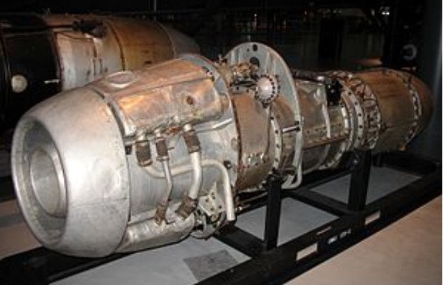
The Ishikawajima Ne-20 (Japanese: 石川島 ネ-20) was Japan’s first turbojet engine. It was developed during World War II in parallel with the nation’s first military jet, the Nakajima Kikka.

The decision to manufacture this engine came about because of the unsuitability of two earlier powerplants selected for the Kikka, the Tsu-11 and the Ne-12. The Ne-20 was made possible by Imperial Japanese Navy engineer Eichi Iwaya obtaining photographs and a single cut-away drawing of the German BMW 003 engine.

In July 1944, the Japanese military attache stationed in Germany returned home with a few photocopies, including a cross-section of the BMW 109-003 turbojet and some general materials concerning the Me-262 fighter and Me-163 interceptor. The important data such as the schematic drawings, however, were being transported by a submarine which was sunk.

When details, breaf as they were, of the BMW 19-003 reached Japan, the Army and Navy held a joint conference at which it was decided that a Japanese version of this turbojet held more promise in the short term than Japanese work still in its early stage. This resulted in 4 projects.

The Ne-20 was the navy project headed by Osamu Nagano assisted by Tanegashima at Kugisho in Yokosuka. The Ne-20 was to become the Japan’s most successul turbojet and the other 3 projects were not fully developped in the time available.

It was the Tokyo Ishikawajima Shipyards that was chosen by the navy to be in charge of trial-manufacture and mass production of jet engines (for commercial use also).

Koichi Ichida, chief of the Business Planning Department, National Aerospace Development Agency, says that reciprocal engines were the main power during the war, but Ishikawajima made steam turbine engines for ships.
It was close to a jet engine because of the rotating mechanism. That is why turbo engines were researched for automobile engines as well.

Only a small number of these engines, perhaps fifty, were produced before the end of the war. Two of them were used to power the Kikka on its only flight on August 7, 1945. Only a few of the engines under construction survived. It was also planned to use the engine to power a version of the Ohka kamikaze weapon, but this was not implemented before the end of the war.

Nakashima Aeroplane and Mitsubishi Heavy Industries also were directed to do trial-manufacture with the same one-page diagram from Germany, but both were unable to realize it.

Everything concerning aircraft, including the Ne-20, was either destroyed by the Allied Powers or brought back to the United States.

Three Ne-20s have been preserved:
One at Ishikawajima-Harima’s internal company museum in Tanashi,
Two at the National Air and Space Museum in Washington, DC.

Ne-20
Type: Turbojet engine
Length: 2700 mm
Diameter: 620 mm
Dry weight: 470 kg
Compressor: Axial compressor
Maximum thrust: 475 kgf (4.66 kN, 1,047 lbf) at 11,000 rpm
Ishikawajima Tsu-11

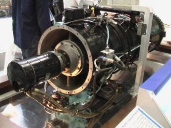
The Tsu-11 was a primitive, motorjet-style jet engine produced in small numbers in Japan in the closing stages of World War II. It was principally designed to propel the Japanese Ohka flying bomb, a kamikaze weapon.

The Tsu-11 used a four-cylinder inverted inline Hitachi Hatsukaze Ha 11 piston engine to drive a single-stage compressor. A fuel injection system was fitted behind the compressor. In operation, fuel would be mixed with the compressed air and the resulting mixture ignited, creating thrust.
The engine was designed to overcome the major shortcoming of the Ohka Type 11 weapons, that of limited range. The Type 11 was powered by solid-fuel rocket motors, which provided tremendous acceleration, but had a very short burn time. The upshot of this was that the Ohka’s carrier aircraft would have to fly very close to the target, making it vulnerable to interception. In practice, most Ohka-carrying bombers were shot down before they ever had the opportunity to launch their weapons. It was reasoned that a jet engine would provide high speed as well as enough range to keep the carrier plane safe long enough to release the Ohka and leave the area.

The engine was first tested hung underneath a Yokosuka P1Y bomber sometime in 1944 and was deemed successful enough to order into production. The Ohka was adapted to accommodate the engine in a lengthened fuselage with jet intakes added at the sides. This configuration was designated Ohka Type 22. The Tsu-11 was also selected to power the Yokosuka MXY-9 Shuka (“Autumn Fire”) – a trainer intended to prepare pilots for the Mitsubishi J8M rocket-powered interceptor. Neither of these aircraft entered service, however, as their development took place too late in the war.

A single example of a Tsu-11 engine exists, preserved at the National Air and Space Museum in Washington DC. In 1997 it was installed in the museum’s Ohka 22 during its restoration. Engineering analysis of the engine during the restoration process suggested that the fuel injection and combustion probably contributed little to the power of the engine, with most of the thrust actually being produced by the compressor – in effect, an afterburning ducted fan engine.

Ishikawajima

Japan
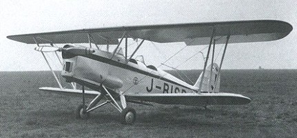
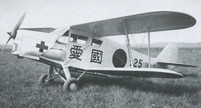
Ishikawajima Kokuki KK was formed at Tokyo in December 1924, with a factory at Tachikawa. Built small batches of 2-seat biplanes: T-2/-3 recon, R-1/-2/-3/-5 trainers and light ambulance (later designated KKY). KKY with 130hp Cirrus replaced by 150hp Ha-12 or Kamikaze radial was developed as KS-I for survey duty while company was being reorganised 1936 as Tachikawa.

Ishikawajima-Hanma Jukogyo Kabushiki Kaisha (Ishikawajima-Harima Heavy Industries Co Ltd)
1962:
2-4
Ote-Machi,
Chiyoda-ku,
Tokyo

Sole manufacturer of aircraft gas-turbine engines in Japan, Ishikawajima-Harima took over the J3 turbojet from the Nippon Jet-Engine Company in 1959, when the latter had completed its five year development programme for the engine.
It is also manufacturing under licence General Electric J79 turbojets to power Japanese-built F-101J Starfighters, and is preparing to produce the General Electric T58 shaft-turbine for helicopter, marine and industrial applications.
Under development is an aft-fan version of the J3, designated J3-F.
The single stage fan will be in line with the turbine and driven by exhaust gases in the main engine, but will be mechanically independent. It is designed to offer a 40 percent increase of thrust compared with the J3, with no increase in fuel consumption.

Isaacs Spitfire

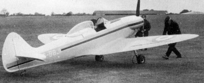
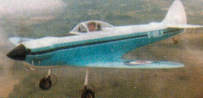
Construction of the 60% replica of the World War 2 Spitfire was begun by John Isaacs in 1969 at Southampton. Wood and fabric construction. Powered by a Rolls-Royce/Continental O-200-A engine, the prototype, c/n.2, later registered G-BBJI PFA.27-10055, first flew in early 1975.

Gallery

Engine: Continental O-200, 100 hp.
Height: 5.6 ft.
Length: 19.3 ft.
Wing span: 22.1 ft.
Wing area: 87 sq.ft.
Weight empty: 805 lbs.
Gross: 1100 lbs.
Fuel cap: 13 USG.
Speed max: 150 mph.
Cruise: 130 mph.
Range: 200 sm.
Stall: 47 mph.
ROC: 1100 fpm.
Take-off dist: 600 ft.
Landing dist: 450 ft.
Service ceiling: 15,000 ft.
Seats: 1.
Landing gear: tail wheel.

Isaacs Fury / PFA Isaac Fury

Fury II

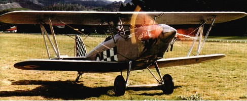
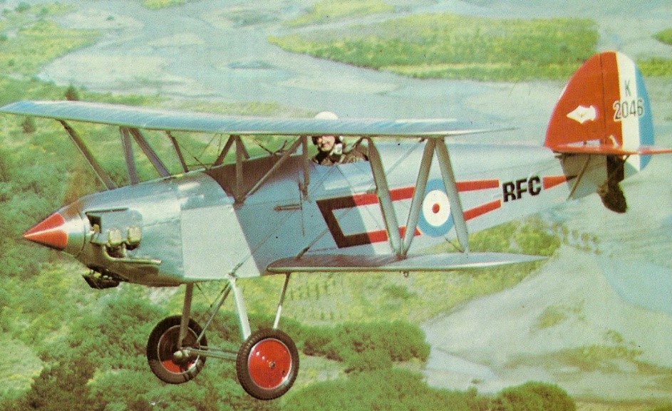
Designed by John Isaacs, the Fury is a 7/10 scale, single seat wooden replica of the famous Hawker Fury biplane of the 1930’s. The Isaacs Fury Mk 1 prototype G-ASCM first flew in 1963 powered by a 65 hp Mikron III engine. In 1967 the prototype was modified to Mk 2 standard by installing a 125 hp Lycoming O-290 engine. This aircraft is stressed to 9g for aerobatics. Normal load limits are +5 and -1G.

Fury II

The fuselage is a spruce structure of rectangular cross-section, with a curved turtlede eking and plywood covered. The wing is made up of solid spruce, warren girder ribs, internal diagonal wooden bracing and fabric covering. Ailerons are on the top wing only. No flaps are fitted. N type cabane and interplane struts support the wings which have conventional external wire bracing. The airfoil section is RAF 28. The empennage is a wooden structure utilising solid spars, girder ribs and fabric covering. The tailplane is strut braced. The fixed landing gear incorporates rubber cord shock-absorption and 3.25 x 14” wheels. A 10 Imperial gallon fuel tank is located aft of the firewall. A luggage locker is provided behind the cockpit.

It is only offered as a scratch built project with plans from John Isaacs. It is also an approved type of aircraft by the PFA in the UK.

John Isaac had sold 200 sets of plans (revised in 1994) by 1998. The plans were then marketed by the Popular Flying Association.

Gallery

Engine: Lycoming
Wing span: 6.4 m
Wing area: 11.4 sq.m
MAUW: 454 kg
Empty weight: 333 kg
Fuel capacity: 68 lt
Max speed: 185 kph
Cruise speed: 160 kph
Minimum speed: 72 kph
Climb rate: 8 m/s
Seats: 1
Fuel consumption: 25 lt/hr
Plan price (1998): $120

Engine: Lycoming 0-290, 125 hp.
Span, upper wing: 2l ft 0 in.
Lower wing: 18 ft 2 in.
Length: 19 ft 3 in.
Wing Area: 123.8 sq.ft.
Wing Loading: 8.1 lb/sq.ft.
Fuel cap: 18 USG.
MAUW: 1000 lbs.
Weight Empty: 730 lb.
Stall Speed: 38 mph.
Cruise: 100 mph.
Vne: 135 mph.
Top speed: 115 mph
Range: 200 sm.
Take-off dist: 400 ft.
Vne: 160 mph.
ROC: 1600 fpm.
Ultimate Loading: +9/-4.5g.

Engine: Lycoming 0-235-C, 115 hp.
Range 160km (100 miles).
MTOW: 1000 lbs.
Empty wt: 675 lbs.
Wing span: 21 ft.
Stall: 30 kts.
ROC: 1400 fpm.
Load limits: +9 / -4.5G.

Engine: Lycoming 0-235 C2A, 125hp.
Prop: Henry 428 72in dia/44in pitch
Cruise 85kt @2400rpm
ROC: 1500fpm
Fuel burn @ cruise: 26 lt/hr
Load: +9/-5.

Irwin Meteorplane M-T-2 / SP-1

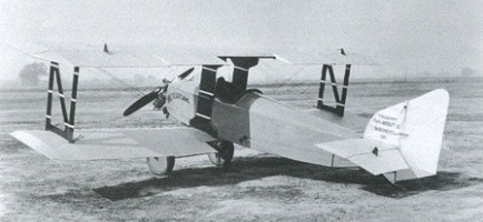
After the First World War the company built an improved version of the M-T, the M-T-2, powered by a 20 hp Meteor engine. The 1926 M-T-2, or SP-1, was of plywood construction and sold for $1,165.

By Irwin’s estimate about 40 were sold, including N2616, plus an unrecorded number sold as kits for $350, including N579M, N3685, and N7788, less motor (the Meteormotor went for $625). One of the world’s first successful small, personal airplanes.

Engine: Irwin Meteormotor, 25hp
Wing span: 14’0″
Length: 12’0″
Useful load: 175 lb
Max speed: 85 mph
Cruise speed: 75 mph
Stall: 24 mph
Range: 200 mi
Seats: 1