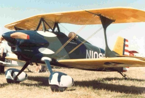
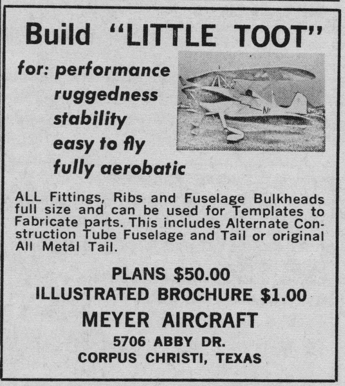
George W. Meyer was already a well known craftsman and model airplane builder prior to his full size project. He started the Little Toot by drawing it in ½ inch to the foot scaled drawings and proceeded to build a metal, 1/24 scale model of his dreams. The model duplicated what he wanted in the full size airplane including a scale metal engine. Many of the building processes were refined in the small model, prior to starting the full size project in 1952.
The full size airplane performed perfectly on the first flight with only a slight adjustment to the rudder trim tab. The first flight was flown on February 2, 1957 in Corpus Christi, Texas. The pilot for the test flight was a great lady pilot by the name of Pauline Glasson.
All the test hours were flown off and the plane came through with flying colours. The plane was fully aerobatic, and had no bad habits in stall or spin type maneuvers. George originally intended for the Toot to be a one of a kind airplane, but the requests for plans soon overwhelmed that decision so he began to produce plans with all of the modifications incorporated into them that he had made during the project.
The Little Toot took the top award from Mechanic Illustrated for “Outstanding Achievement in a Homebuilt Aircraft” at the 1957 EAA convention in Milwaukee. “Little Toot” also won the Paul H. Poberezny Award two years in a row. Year 1999 and 2000.
The single seat fuselage is an all-metal structure with metal-covered steel tube construction from rear of cockpit forward, and metal monocoque rear of tubular fuselage cockpit forward section. Plans also provide you with an alternate full Tube and Fabric fuselage construction.
It features all wood wings, two 1″ thick spar structure with fabric covering, and NACA 2212 wing section, 8 degrees sweepback on the top wing, and 2.5 degrees of dihedral on lower wing. There is 2 degrees incidence on both upper and lower wings. Braced biplane type with Cabane and I-struts. Fabric covered all metal full-length ailerons on lower wings only. No Flaps. Little Toot has a structure stressed to 10- and 10+ G’s
The original was fitted with a Continental 90-hp engine, but power plant options include 4-cylinder engines of up to 200 hp, or six cylinders up to 250 hp. The Little Toot has an eight-degree sweepback on the upper wing. The straight lower wing carries fabric covered, metal, almost full-span ailerons that give the ship an unusually high roll rate. Fiberglass engine cowlings are now available. A baggage compartment is located behind the pilot seat.
There are two tail type options. A cantilever all aluminum structure, or a tubular 4130 chrome-moly steel, fabric covered. Both have a trim tab in the port elevator. The main gear is fixed cantilever spring steel from Cessna 140/120, or new aluminum gear with integrated brake line, and a steerable tailwheel.
Jan 65
Wing span (both): 19 ft in Fuselage length: 16 ft 6 in Total height: 7 ft Weight empty: 914 lb Gross weight: 1320 lb Max wing loading: 10 lb/sq foot Max power loading: 13.7 lb/sq foot Fuselage fuel tank: 19 USG Opt. wing fuel tanks: 18 USG Total fuel capacity: 37 USG Roll rate: 120 deg/sec Vne: 200 Mph V2min (min takeoff speed): 65 mph VFTO (Final takeoff speed): 70 mph VC (most efficient cruising speed): 125 mph VD (design diving speed): 200 mph VDF (demonstrated flight diving speed): 160 to 180 mph in aerobatic configuration VFC (Max speed for stability characteristics): 90 mph VH (Max speed in level flight at max power): 138 mph VLOF (Lift-off speed): 55-60 mph VMC (Minimum control speed in flight): 48 mph Vmcg (Minimum control speed on the ground): 40 mph VMO (Maximum operating limit speed): 180 mph VNO (Maximum structural cruising speed): 138 mph VR (Rotation speed): 60 mph VRef (Landing reference speed): 70 mph VSO (Power off stall speed): 48 mph VY (Best rate of climb): 100 mph Max speed at sea level 125 hp: 135 mph Max speed at sea level 150 hp: 150 mph Max speed at sea level 180 hp: 165 mph Normal cruising speed 125 hp: 125 mph Normal cruising speed 150 hp: 135 mph Normal cruising speed 180 hp: 145 mph Max rate of climb 125 hp: 1600 fpm Max rate of climb 150 hp: 2000 fpm Max rate of climb 180 hp: 2150 fpm Range (Standard with wing tanks)125 hp: 260 sm Range (Standard with wing tanks)150 hp: 240 sm Range (Standard with wing tanks)180 hp: 220 sm
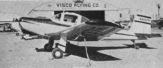
Postwar production included MAC 125 and MAC 145 two-seat cabin monoplanes with Continental engines.
The MAC 145, introduced in 1948, is a higher-powered development of the MAC 125-C, the first post-war design of Meyers Aircraft Company. The MAC 145 differs in having a 145 hp Continental C145-2H engine.
Both were side-by-side two-seat cabin monoplane of all metal construction. A small series of MAC 145 were built.
The MAC 125 and MAC 145 developed into the Micco SP 20 and SP 26.
MAX 125 Engine: 125 hp Continental C125 Seats: 2
MAC 145 Engine: 145 hp Continental C145-2H Wingspan: 30 ft Wing area: 149 sq.ft Length: 21 ft 4 in Height: 8 ft 6 in Empty weight: 1135 lb Loaded weight: 1735 lb Max speed: 166 mph Cruise: 145 mph ROC: 950 fpm Service ceiling: 18,000 ft Range: 600 mi Seats: 2
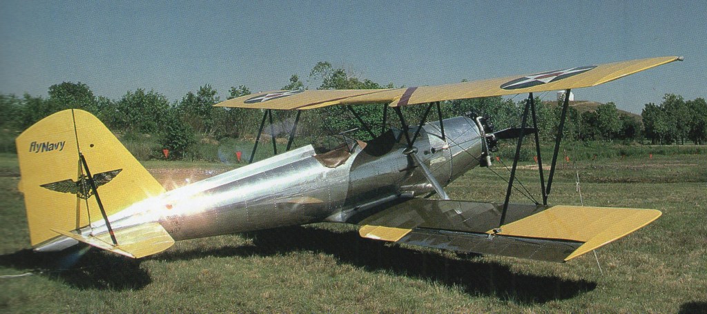
Meyers developed the OTW-160 biplane trainer and MEW-165W monoplane trainer for U.S. schools within CAA War Training scheme. The OTW featured an all metal fuselage mated with fabric-covered wings and horizontal stabiliser. A total of 102 were built.
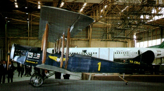
To celebrate its 75th anniversary, Mexicana built a 75%-size airworthy replica of a Nebraska Aircraft Company Lincoln Standard biplane, the first aircraft type used by its predecessor, Compañia Mexicana de Transportacion Aérea SA.
In 1784, less than a year after the first balloon flights, Jean Baptiste Marie Charles Meusnier de la Place presented a plan for a military dirigible, driven by men turning a hand crank to operate a propeller. It would have been the world’s first airship, but it was never built.
In 2002 the BBC series “Building the Impossible” set out to recreate Meusnier’s design to find out whether it would have worked. Cameron Balloons constructed the replica which was filled with helium for safety, instead of the flammable hydrogen proposed by Meusnier. A speed of about three miles per hour was achieved, although the steering sail was too small and steering was difficult.
Jean Baptiste Marie Charles Meusnier de la Place (1754 — 1793) was a French mathematician and engineer. In 1784, less than a year after the first balloon flights, he presented a plan for a military dirigible, driven by men turning a hand crank to operate a propeller. It would have been the world’s first airship, but it was never built.
In 2002 the BBC series “Building the Impossible” set out to recreate Meusnier’s design to find out whether it would have worked.
Alan Arnold Griffith published a seminal paper in 1926, An Aerodynamic Theory of Turbine Design, that for the first time clearly demonstrated that a gas turbine could be used as a practical, and even desirable, aircraft powerplant. The paper started by demonstrating that existing axial compressor designs were “flying stalled” due to their use of flat blades, and that dramatic improvements could be made by using aerofoil designs instead, improvements that made a gas turbine practical. It went on to outline a complete compressor and turbine design, using the extra exhaust power to drive a second turbine that would power a propeller. In today’s terminology the design was a turboprop. In order to prove the design, Griffith and several other engineers at the Royal Aircraft Establishment built a testbed example of the compressor in 1928 known as Anne, the machinery being built for them by Fraser and Chalmers. After Anne’s successful testing they planned to follow this up with a complete engine known as Betty.
In 1929 Frank Whittle’s thesis on pure jet engines was published, and sent to Griffith for comment. After pointing out an error in Whittle’s mathematics, he went on to deride the entire concept, saying that the centrifugal compressor Whittle used would be impractical for aircraft use due to its large frontal area, and that the use of the jet exhaust directly for power would be extremely inefficient. Whittle was distraught, but was convinced that he should patent the idea anyway. Five years later a group of investors persuaded him to start work on what would be the first working British jet engine.
Griffith continued development of his own concepts, eventually developing an advanced compressor design using two contra-rotating stages that improved efficiency. His partner, Hayne Constant, started discussions in 1937 with Manchester-based Metrovick, a maker of steam turbines, to produce the new machinery. Incidentally, Metrovick had recently merged with British Thomson-Houston, another turbine builder who were supporting Whittle’s efforts.
A contract for development work was eventually given by the Air Ministry the next year, and work on Betty, also known as the B.10, started. In 1939 the team, including Metrovick engineers led by David Smith, started work on a flyable design, the F.1. Compared to the centrifugal-flow Whittle designs, the F.1 was extremely advanced, using a nine-stage axial compressor, annular combustion chamber, and a two-stage turbine (the second driving a propeller).
In April 1939, Whittle gave a startling demonstration of his experimental engine, the WU, running it for 20 minutes at high power. This led to a rash of contracts to build a production quality design suitable for aircraft use. Development had just started on the F.1 when Whittle started building his W.1 design, planning to install one for flight in the Gloster E.28/39 the next year. Smith decided to end development of the F.1 and move on to a pure-jet instead, starting work on the otherwise similar F.2, Freda, in July 1940.
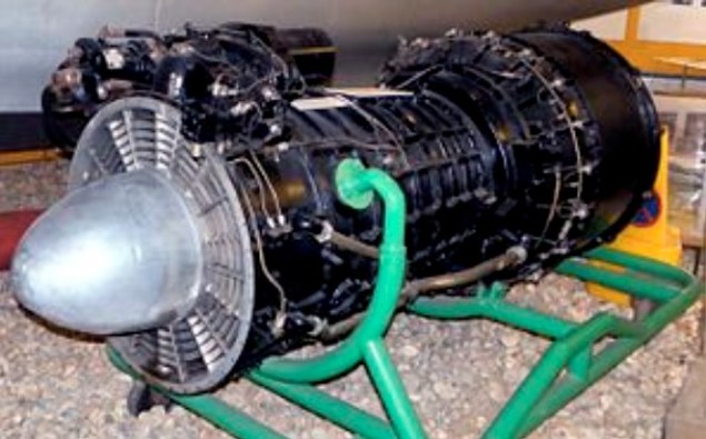
Development of the F.2 progressed rapidly, and the engine ran for the first time in November 1941. By this point there were a number of engines in development based on the Whittle concept, but the F.2 looked considerably more capable than any of them. Flyable versions, the F.2/1, received its test rating in 1942 and were flown on an Avro Lancaster test-bed (the first prototype Lancaster, s/n BT308) on 29 June 1943, mounted in the rear fuselage. Production quality versions were tested on the F.9/40M (Gloster Meteor) s/n DG204/G which made its first flight on November 13, 1943. These were installed in Messerschmitt Me 262 type underslung nacelles.
As expected, the engines were more powerful than the Whittle design, first delivering 1,800 lbf (8 kN) but soon scaling up to well over 2,000 lbf (8.9 kN). Around this time, the Whittle W.2B was developing 1,600 lbf (7.11 kN). However, the engine suffered from a number of problems that cast doubts on its reliability. These were primarily due to hot spots building up on the turbine bearing and combustion chamber. The latter, in turn, caused warping and fractures of the turbine inlet nozzles.
To address these problems, in August 1942 a minor redesign delivered the F.2/2, which changed the turbine material from Rex 75 to Nimonic 75, and lengthened the combustion chamber by 6 inches (150 mm). Thrust was improved to 2,400 lbf (11,000 N) static, but the problems with overheating remained.
Another attempt to solve the overheating problems resulted in the more highly modified F.2/3 during 1943. This version replaced the original annular combustion chamber with can-type burners like those on the Whittle designs. This appears to have solved the problems, raising the thrust to 2,700 lbf (12,000 N) in the process. However, by this time it was decided to move on to a much more powerful version of the engine.
Development of the F.2 continued on a version using a ten-stage compressor for additional airflow driven by a single stage turbine. The new F.2/4 – the Beryl – initially developed 3,250 lbf (14.45 kN) and was test flown in Avro Lancaster Mk.II s/n LL735 before being installed in the Saunders-Roe SR.A/1 flying boat fighter. Thrust had already improved to 3,850 lbf (17.1 kN) for the third prototype, and eventually settled at 4,000 lbf (17.8 kN). In comparison, the Derwent developed only 10.9 kN in its ultimate form; making the Beryl one of the most powerful engines of the era. Development of the SR.A/1 ended in 1947, ending development of the Beryl along with it. Nevertheless a Beryl from the SR.A/1 prototype was removed and used by Donald Campbell for early runs in his famous 1955 Bluebird K7 hydroplane in which he set seven water speed records between 1955 and 1964.
In 1942 MV started work on thrust augmentation. The resulting Metropolitan-Vickers F.3 was the first British turbofan engine to be designed, built and tested. Indeed, it could be said that the F.3 was also the very first 3-shaft jet engine to be built, although the configuration was completely different to that of the much later Rolls-Royce RB211 turbofan series, since the fan was located at the rear of the engine, not unlike that of the General Electric CJ805-23. Using a stock F.2/2, MV added a separate module to the rear of the engine (directly behind the HP turbine) which comprised contra-rotating LP turbines attached to two contra-rotating fans. Apart from the first stage nozzle guide vanes, the LP turbine was completely statorless, with four consecutive rotor stages. Rotors 1 and 3 drove the front fan clockwise (viewed from front), whereas the rear fan was driven anticlockwise by rotors 2 and 4. Although the front fan had inlet guide vanes, there were no vanes between the contra-rotating fan rotors or, downstream, any exit guide vanes. The core and bypass streams exhausted through separate coaxial propelling nozzles.
The project was generally successful, raising static thrust from around 2,400 lbf (11,000 N) to 4,000 lbf (18 kN). More importantly, specific fuel consumption fell from 1.05 to 0.65 lb/hr/lbf, which was the true aim of the project. The weight increase for all the extra turbomachinery and ducting was fairly significant, however. A bonus was that the team noticed that the cold air from the fan mixed with the hot exhaust from the gas generator, resulted in a marked decrease in noise levels, the first time such an effect had been recorded (it was re-discovered during a major NASA project in the 1960s).
Although the F.3 progressed nicely, development was curtailed by the pressures of war. When the war ended the F.2/2 was no longer current, so some of the ideas were applied to the more up-to-date F.2/4 to produce the Metropolitan-Vickers F.5 propfan.
Following on where the F.3 left off, the F.5 was a version of the F.2/4 with an open rotor (unducted) thrust augmenter added to the end of the jet pipe, somewhat remote from the HP turbine The 5 ft 6 in diameter fixed pitch propellers, which contra-rotated, were driven by a 4-stage statorless LP turbine unit, similar to that of the F.3. The General Electric GE36 UDF demonstrator of the 1980s also used a similar LP turbine arrangement, albeit with many more stages. In addition, the GE36 propellers were variable pitch. With both propfans, the LP turbine arrangement enabled the propellers to rotate at optimum speed, without the need for a reduction gearbox.
Static thrust increased from the 3500lbf of the F.2/2 to in excess of 4,710 lbf (21,000 N), with a corresponding reduction in specific fuel consumption. Relative to the parent turbojet, the weight increase for this propfan configuration was about 26%, compared to 53% for the F.3 turbofan. Unfortunately, the company cancelled development when they sold their gas turbine business to Armstrong Siddeley in 1946.
Development of the F.2 ended in 1944. Development of the basic concept continued, however, eventually leading to the considerably larger F.9 Sapphire. However, in 1947, Metrovick left jet engine production and their design team moved to Armstrong Siddeley. The Sapphire matured into a successful design, initially besting the power of its Rolls-Royce contemporary, the Avon. Design features of the Metrovick line were worked into Armstrong Siddeley’s own line of axial compressor turboprops, although Armstrong Siddeley dropped Metrovick’s use of gemstone names for their engines in favour of continuing with animal names, in particular snakes.
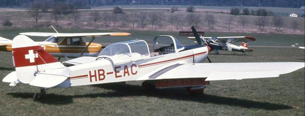
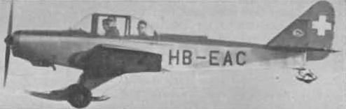
In 1953 Meteor took over the aeronautical designs and equipment of Francis Lombardi & Co. (formerly Azionari Vercellese Industrie Aeronautiche-AVIA) of Vercelli, whose products included the FL.3 of which 566 were built between 1939 and 1948. Meteor redesigned the FL.3 with tubular steel construction, a cut-down rear fuselage and bubble canopy. A total of 37 Meteors of various kinds was built during the period up to 1959 and several of these aircraft were sold as crop sprayers and with ski or float landing gears. The different Meteor models were:
FL.53, two-seat trainer and tourer, powered by a 65 hp Continental A65 engine (8 built). FL.53BM, basic FL.53 fitted with 90 hp Continental C90-12F engine (4 built). FL.54, three-seat FL.53 with 85 hp or 90 hp Continental (10 built). FL.55, four-seat FL.54 with strengthened airframe and 135 hp Lycoming O-290-3 engine (4 built). FL.55BM, basic FL.55 with modified fin and rudder and 150 hp Lycoming O-320-A1A engine (10 built).
MOUNTAIN RESCUE METEOR 55B version of the Italian Meteor (Lombardi) FL5 series. Four supplied to Switzerland.
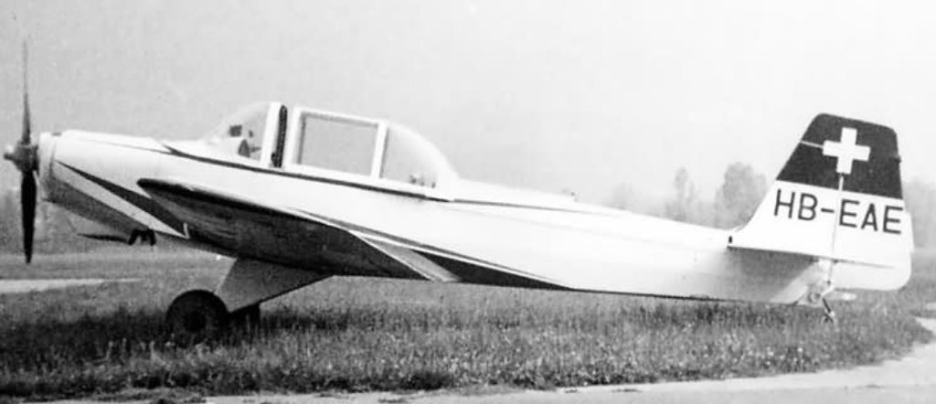
FL.55CM, basic FL.55 with 180 hp Lycoming O-360-A1A engine (1 built).
Meteor FL.55CM (HB-EAE c/n 1134)
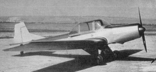
Super, basic FL.55 with enlarged vertical tail and 220 hp Meteor Alpha engine (1 built).
Meteor Super (220 hp Meteor Alfa 4 engine)
Bis, two-seat Super with 110 hp Meteor Alpha 2 engine (number built unknown).
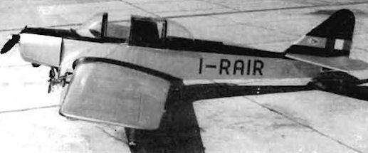
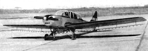
This Meteor FL-55 has been modified in Italy for crop-spraying. Part of the insecticide tank can be seen in the cockpit behind the pilot’s seat.
From Italy comes another form of crop spraying using a wind generator forward of the undercarriage. The aircraft is the Meteor FL55 “Agricolo” I-FULU (150 hp Lycoming).