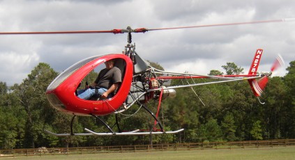
Eagle R&D Helicycle

First flown in April 1985.
After crashing his demonstrator Helicycle in 1999, Schramm did find investment. The result is a single seat partially enclosed helicopter which flies conventionally or as a compound with an additional pusher engine. An ultralight version uses Rotax 503. Elastomeric rotor head, long-life blades. Optional turbo version has full power to 10,000 ft.
Engine options are: 74 hp Rotax 618 derated to 60 hp, Rotax 503. Compound engine: 45 hp Zenoah. Rotor blades: 21’ x 7” all aluminium by Eagle R&D.
The HELICYCLE in it’s normal configuration is designed to cruise along side the industry standard R-22. Landings and take offs at above 9000 ft. are possible because of a 7.5/1 power to weight ratio. The same as the Hughes 500.
The Helicycle features include a fully harmonized rotor, a modulated collective system, very low 2-per-rev vibration level due to elastomeric thrust bearings, generous flapping angle for low “G” and slope landing conditions, control friction devices, and electronic throttle control.
The cyclic control in the HELICYCLE accurately models the feel of the R-22. With a high degree of control power, it provides a transition for the R-22 qualified student pilot. To aid in controlling costs, the Helicycle has 12 grease zerks and 2 sliders that do need a minute or two of attention now then, the rest of the bearings are sealed. The Helicycle certified level lifetimes for it’s drive train and rotor system components are 1500-2000 hrs.
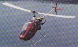
Engines: 2 x McCulloch
Top speed: 105 mph
Cruise: 90 mph
Range: 160 sm
Rate of climb: 900 fpm
Service ceiling: 9000 ft
Fuel capacity: 12 USG
Empty weight: 395 lb
Gross weight; 672 lb
Length: 21.7 ft
Height: 7 ft
Disk span; 20 ft
Disk area: 314 sq.ft
Seats: 1

Helicycle E
Cruise: 95 mph (120 compound).
Top speed: 105 mph (135 compound).
Empty wt: 395 lbs.
Useful load: 277 lbs (320 compound).
Gross wt: 820 lbs.
Width: 4’2”.
Height: 7’.
Length: 19’7”.

Engine: Rotax 618, 60 hp
MAUW: 310 kg
Empty weight: 179 kg
Fuel capacity: 45 lt
Max speed: 170 kph
Cruise speed: 145 kph
Minimum speed: 0 kph
Climb rate: 4.5 m/s
Seats: 1
Fuel consumption: 16 lt/hr
Kit price (1998): $25,000
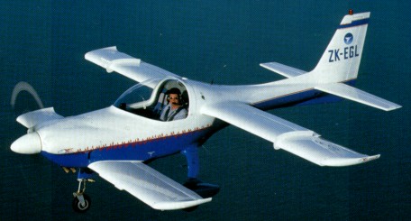
Eagle Aircraft [2] 150

Eagle 150B

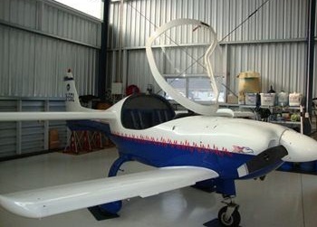
The original design came from an American, John Roncz, who had worked with Burt Rutan on numerous projects. The first flight of the Eagle 150A was in March 1988 using an Aeropower engine. The Eagle 150A was certified on 13 November 1996 and a total of fifteen were built with sales in Perth, Sydney and Asia. The 150B Model was certified in Australia on 11 November 1997, FAA certification followed on 11 February 1999, and its New Zealand Type Acceptance Certificate was issued on 5 May 1999.
Apart from the limited use of fasteners, brackets and control system components, the 150B structure is made entirely of aerospace grade composites, such as kevlar, carbon fibre, nomex and fibreglass. Most of the structure is of a sandwich type construction with carbon fibre laminates separated by a nomex core. Kevlar is used around the cockpit area to improve the crashworthiness of the aircraft.
The undercarriage “bow” is made of fibreglass as it is more flexible than carbon fibre. The basic fuselage consists of two sub-assemblies — the forward fuselage is the canard, cockpit area and the mainplane and the rear fuselage is the horizontal and vertical stabiliser. These are joined just be¬hind the fuel tank which is located behind the seat-back bulkhead — and are fastened by a ring of structural screws accessible from the outside. This allows the aircraft to be broken down in under half an hour to be placed on a trailer. Fuel from the tank feeds directly to the engine through an engine-driven mechanical pump. A two-stage pump is provided to supply both low pressure and emergency fuel flow.
The canard and the mainplane are structurally integral with the forward fuselage and are bonded into place during assembly of the forward fuselage. Similarly, the vertical stabiliser is part of the rear fuselage and can not be subsequently removed.

150B

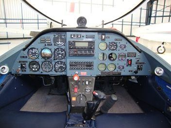
The flight controls are operated from a centrally located “jet fighter” style control column, which has trigger to talk, a button to change radio channels and a hat switch for the electric elevator trim.
The 150B is comfortable to fly with a central padded arm rest to lean on when in control and good air vents are found on the edge of the instrument panel. The aircraft’s two sets of rudder pedals are individually adjustable through a switch on the cabin wall console that operates an electric actuator. Pitch control is achieved through a conventional elevator fitted to the horizontal stabiliser — no elevator is fitted to the canard. All surface controls are operated through pushrods and not pulleys and cables. A pitch trim indicator for the electrical elevator trim tab is found on the instrument panel.
Like the pitch, control of yaw is through a conventional rudder fitted to the vertical stabiliser. The rudder control is combined with the brake system and is unconventional in that the brake action is not associated with a pedal rotation, that is, toe brakes. The aircraft is fitted with a fixed tricycle undercarriage with a free-castoring nose wheel. The first movement on the pedal (about 5 cm of travel) operates the rudder in the conventional way and further pressure begins the application of the main wheel brakes; when force is applied to both pedals simultaneously both wheel brakes act together. This is new to a lot of pilots and it is very important to feel the pedal forces.
Ailerons are fitted to the outer section of the mainplanes and, as expected, these provide roll control. An aileron trim, found on the central console, uses a small torque tube to offset the centre position of the control column in the roll.
The 150B has trailing-edge slotted flaps fitted to both the canard and the mainplane which are lowered or raised by a switch (duplicated on both sides of the instrument panel). All four flap segments are interconnected and are operated by a single electrical actuator driving a pushrod mechanism. The electric flaps are continuously variable and are rather different with coloured marks on the inboard face of the canard tips indicating their position. This will be changed to a light indicator on the panel (which will be retrofitted).
The one-piece, front hinged canopy offers excellent visibility and requires most pilots to take a hat for protection from the sun. The canopy can be secured in a partly open position for taxiing during hot days and when the canopy is closed it is locked by a single lever behind the pilot’s head.

Approved maneuvers are normal flying, stalls and lazy eights, chandelles and step turns in which the angle of bank is not more than 60 degrees. With the flaps retracted, limits are ±3.8g and -l.9g, but there are plans for this be increased to +8.8g and -4.3g.The Eagle 150 had the MTOW increased from 640 kg to 650 kg by the Australian CASA.
Manufacturing of the Eagle 150 moved to Malaysia.

Eagle 150B
Engine: Teledyne Continental IO-240B, 125 hp.
TBO: 2000 hrs
Fuel type: 100/100LL
Prop: McCauley fixed.
Seats: 2.
Height: 7 ft 7 in (2.32m).
Main wingspan: 23 ft 6 in (7.16m).
Wing area: 95 sq. ft
Wing loading: 14.5 lb/sq.ft.
Canard wingspan: 16 ft (4.88m).
Pwr loading: 11.2 lb/hp.
Overall length: 21 ft. 2 in.
Height: 7 ft. 7 in.
Wheel base: 4 ft. 7 in.
Wheel track: 6 ft. 4 in.
Seating capacity: 2
Cabin width (in.): 42 Cabin height (in.): 32
Baggage capacity (lbs.):80
Empty wt: 941 lbs (427 kg).
MTOW: 1430 lbs (650kg).
Useful load: 489 lbs (223kg).
Payload with full fuel: 333 lbs (151 kg).
Max ramp weight: 1430 lb
Max landing weight: 1430 lb
Ave fuel consump: 23 lt/hr.
Fuel cap Total: 100lt (156 lbs, 71 kg),
Useable fuel: 97lt / 153 lb / 69.5 kg / 26 US gal
Endurance With res: 2.8 hr.
Max range (w/ reserve) 75% power: 520 nm
Baggage cap: 100 lbs (45 kg).
Take-off dist (ground roll): 834 ft.
Take-off dist (50-ft): 1145ft.
ROC: 1051 fpm@ 77 kts.
Max X-wind: 15 kt.
Max level speed: 130 kts.
Cruise speed @ 75% power: 120 kts @ 2000 ft.
Ldg dist (ground roll): 513 ft.
Ldg dist (50ft): 1198ft.
Service ceiling: 15,000 ft
Vx (best angle of climb): 74 KIAS.
Vy (best rate of climb): 77 KIAS.
Va (manceuvring): 106 KIAS.
Vfe (max flaps): 89 KIAS.
Flaps (0-20 degrees): 104 KIAS.
Vno (max structural cruise): 129 KIAS.
Vsi (stall clean): 55 kts.
Vso (stall): 45 kts (full flaps).
Vne: 165 knots
Landing gear type: Tri/Fixed
Price: $119,000

Eagle Aircraft [2] XDS / X-TS

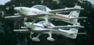
Composite Industries Limited (CIL) was formed to develop the aircraft initially designated the Eagle XDS (Eagle X Dual Seater). A name change followed the thought that XDS emphasised a training role and XTS Eagle two seater was adopted instead. After a prototype the design was frozen for two pre production prototypes.
The Eagle prototype uses a 100hp Continental 0 200 engine to give a 800 fpm rate of climb, 115 knot cruise, weighs 959 kgs at Max T/O weight with a minimum airspeed of 44 knots.
There are two major changes incorpo¬rated in the pre production prototypes. The fuselage is three inches deeper in the cockpit area as a result of a quest to provide a safety “crush zone” and the undercarriage was being changed from tapered struts to legs attached to rubber blocks in compression.
The aircraft failed to meet the JAR-VLA requirements, and received a special category certificate of airworthiness from Australia’s CAA. The stall speed exceeded the permitted 45 kts by 2 kts, at MAUW and forward C of G.

Engine: Continental IO-240 125hp.
TBO: 2000 hrs.
Cruise: 120 kts.
Fuel flow: 23 lt @ cruise.
Climb: 1100 fpm.
Service ceiling: 15,000 ft.

Eagle [1] DW-1 Eagle

Deliveries of Eagle Aircraft’s new ag-¬plane, manufactured by Bellanca, were planned to begin in October 1979. Designed from advanced glider technology, which en¬hances fuel efficiency, the Eagle was cer-tificated with 220 and 240 hp Continen¬tals and 275 and 350 hp Jacobs (all radi¬als); certification was pending with the 300¬hp Lycoming opposed powerplant.

Wood wings and steel tube fuselage, all Dacron-covered; spoilers on top surface of lower wings for more precise control at spray speed (65mph).

An agreement with Bellanca Aircraft Corporation of June 1979 was for Bellanca to manufacture Eagle on its behalf. Eagle production lasted until the early 1980s.

Eagle 300
First built: 1980.
Engine: 1 x Lycoming IO-540, 300 hp.
TBO: 1500 hrs.
Prop: Hartzell 3 blade, constant speed 86 in.
Seats: 1.
Length: 26 ft.
Height: 10.9 ft.
Wingspan: 55 ft.
Wing area: 386 sq.ft.
Wing aspect ratio: 15.1.
Max ramp wt: 5400 lbs.
Max take off wt: 5400 lbs.
Standard empty wt: 2650 lbs.
Max useful load: 2750 lbs.
Max landing wt: 4000 lbs.
Wing loading: 13.5 lbs/sq.ft.
Power loading: 18 lbs/hp.
Max useable fuel: 426 lbs.
Hopper capacity: 250 USG.
Climb rate: 750 fpm.
Climb @ 8000 ft: 450 fpm.
Service ceiling; 20,000 ft.
Max speed: 100 kts.
Working speed: 100 kts.
Fuel flow @ working speed: 103 pph.
Endurance @ working speed: 3.9 hr.
Stalling speed clean: 48 kts.
Turbulent air penetration speed: 103 kts.
Fixed tail-wheel undercarriage.
Fitted with spoilers.

EAA Pee Wee    

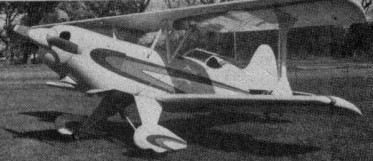
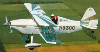
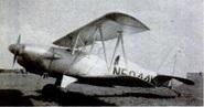
Single seat single engined biplane with con¬ventional three axis control. Conventional tail. Control inputs through stick for pitch/roll and pedals for yaw. Wings braced by struts. Undercarriage has three wheels in tail drag¬ger formation. Aluminium tube framework, with optional pod. Engine mounted between wings driving tractor prop¬eller.
Named Pee Wee after an early lightweight aircraft developed by Joe Kirk, one of EAA’s directors in the ’50s and ’60s, the Pee Wee machine is a tractor biplane powered by a KFM opposed twin engine with electric start. The design allows a pod to be incorporated, so that if the builder wishes he or she can take advantage of the engine heat to warm the feet.
The Princeton Sailwing shape is used in the wing construction and, as befits a biplane, a tail dragger undercarriage is fitted.

Engine: KFM 107.
Empty weight 220 lb, 100 kg.

EAA Super Acro-Sport

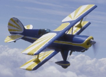
This further development of the Acro-Sport is intended for unlimited international-class aerobatic competition. Though basically similar in appearance to its counterpart, the Super Acro-Sport takes advantage of a more powerful engine turning a fixed-pitch prop, an improved roll rate and inverted flight capabilities. Its two wings have almost sym¬metrical airfoil sections. Also added was a trim tab on the starboard elevator and a servo tab on the port side.

Engine 200-hp Lycoming.
Gross Wt. 1350 lb.
Empty Wt. 884 lb.
Fuel capacity 20 USG
Wingspan 19 ft 7 in
Length 17 ft 6 ft
Top speed 156 mph
Cruise 135 mph
Stall 50 mph
Climb rate 3700 fpm
Ceiling 15,000 ft
Takeoff run 125 ft
Landing roll 800 ft
Range 300 miles

EAA Acro-Sport II

The Acro II, a two-place larger version of the single-place Acro Sport, can be constructed for little more than its single-place brothers. With its larger wheels, wide landing gear and light gross weight, the Acro II is a fun, docile sport airplane designed for engines ranging in power from 115 to 200 hp. When fitted with a 180-hp Lycoming, its empty weight of 875 pounds. First flown on 9 July 1978, like all Acro Sports, its cockpit is designed to be comfortable for pilots up to 6 ft 6 in and 240 pounds. The airframe is larger than the really “midget” biplanes to avoid “touchy” flight characteristics and allow for more baggage. Designed by Paul Poberezny, the Acro II features an M-6 airfoil with a 43-inch chord.

As with all Acro Sport projects, the fuselage is welded steel tube, wings are spruce and Stits Poly-fiber is used for covering. An excellent aerobatic trainer with responsive controls and docile straight and level flight characteristics. Cruise at 123 mph (180 hp), stall at 53 and max out at 152.

I fly N400GB, an Acro II ser# 573.
Daniel Reed
Aug 2022

Gallery

Engine: Lycoming O-360, 180 hp.
HP range: 115-180.
Speed max: 152 mph.
Cruise: 123 mph.
Range: 300 sm.
Stall: 53 mph.
ROC: 1200 fpm.
Take-off dist: 350 ft.
Landing dist: 800 ft.
Service ceiling: 25,000 ft.
Fuel cap: 26 USG.
Weight empty: 875 lbs.
Gross: 1520 lbs.
Height: 6.7 ft.
Length: 18.85 ft.
Wing span: 21.67 ft.
Wing area: 152 sq.ft.
Seats: 2.
Landing gear: tail wheel.

EAA Acro-Sport

This biplane was designed by EAA President Paul Poberezny who wanted to come up with a plane that could be used in high school industrial arts programs and Civil Air Patrol groups as an educational tool. The first flew in January 1972, less than 12 months after the design was started. The Acro-Sport can be fabricated with tools normally found in a high-school shop. It is built with steel tube covered by fabric and 100- to 200-hp engines.

EAA Acro-Sport Article

1974

Engine: Lycoming IO-360, 180 hp.
Speed max: 152 mph.
Cruise: 130 mph.
Range: 350 sm.
Stall: 50 mph.
ROC: 3500 fpm.
Take-off dist: 350 ft.
Landing dist: 800 ft.
Service ceiling: 25,000 ft.
HP range: 85-200.
Fuel cap: 20 USG.
Weight empty: 739 lbs.
Gross: 1350 lbs.
Height: 6 ft.
Length: 17.5 ft.
Wing span: 19.7 ft.
Wing area: 116 sq.ft.
Seats: 1.
Landing gear: tail wheel.

EAA A-1 Biplane

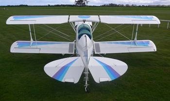
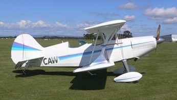
In 1955, the EAA decided to develop a single-seat sport biplane as a service to its members. The prototype was built as a classroom project by students of St.Rita’s High School in Chicago. It flew for the first time on 10 June 1960. The E.A.A. Biplane was designed in response to many requests from members of the American Experimental Aircraft Association for a single seater sports biplane of simple yet rugged construction. The fuselage consists of a welded chrome-moly steel tube frame, to which are fitted plywood formers and wooden stringers, the whole being fabric covered apart from the aluminium coaming panels. Both upper and lower wings have solid spruce spars and built-up wooden ribs, and are internally and externally wire braced. The leading edge to the front spar is aluminium covered, the remainder being fabric covered. Interplane and centre section struts are made of streamline steel tube. A 9.5 Imp. gallon fuel tank is fitted behind the firewall. The empennage, like the fuselage, is built up of welded steel tube and is fabric covered and externally braced. The ailerons which are installed on the lower wing only, are operated by means of push rods, while the elevator and rudder are cable operated. The main undercarriage is built up of steel tube with bungee cords for shock absorption.

EAA Biplane by Herb Dyer

Gallery

Engine: Continental C-85, 85 hp.
Wing span: 20 ft 0 in (6.1 m).
Wing Area: 108 sq. ft.
Wing Loading: 9.4 lb./sq.ft.
Length: 17 ft 0 in (5.18 m).
Height: 6 ft 0 in (1.83 m).
Max TO wt: 1150 lb (522 kg).
Empty Wt. 640 lb.
Fuel capacity 12 USG.
Max level speed: 125 mph (201 kph).
Stall mph 55.
Climb rate 800fpm.
Takeoff run 500 ft.
Landing roll 550 ft.
Range 200 sm.

Działowscy DKD-X Aeromobil

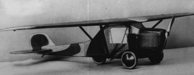
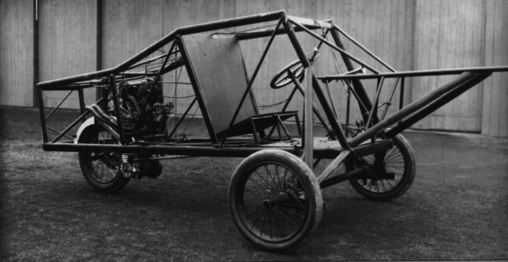
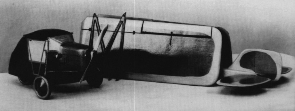
Stanisław Działowski developed the DKD-X “Aeromobil” car project during 1930-1931. The ​​”Aeromobil” took so much that he abandoned the implementation of previous projects. The plane was to serve as an air taxi or a liaison aircraft. In 1931, together with his brother Mieczysław Działowski, they started the construction of a three-wheeled self-propelled trolley constituting the traction part of the future aircraft, which, after detaching the back of the hull and wings, could move on the ground like a car. The construction of the trolley was completed in October 1932 and it was demonstrated on the streets of Krakow in October 1933.

In 1934, Stanisław Działowski developed an improved version of the DKD-X / 2 with a stronger engine with larger dimensions and wing surface, and a more aesthetic appearance. The funds for constructing the prototype were obtained from social contributions, emitting, among others, brick stamps, unfortunately the unit’s command expressed opposition, prohibiting this form of collecting funds. This forced the constructor to suspend work on advanced construction.

A two- or three-seater high-winged craft with mixed construction. The wings were double-spared, wooden, supported by V-braces, and folded for hanger and transport. The nose was covered with plywood, the remaining part with fabric.

The hull trolley was truss welded from steel pipes, covered with fabric. The front part of the fuselage contained a cabin with two seats next to each other, in the second version there was a third seat or place for a stretcher, it was covered with sheet metal. The back of the fuselage is removable from the trolley, was welded from steel pipes, covered with fabric.

A three-wheeled chassis provided with two steering wheels at the front and one wheel driven by gearboxes at the rear. The front wheels were fixed. During the flight, the wheel with the drive was to be concealed in the hull, and to move on the ground, extended to 1/3 of the height of the wheel. The rear wheel was driven by a separate small engine.

In the opinion of IBTL, it was stated that DKD-X will reach the calculated speed of 210 km / h, and only 140 km / h. This reduced the attractiveness of the offer. The severe illness that Stanisław Działowski later underwent pushed for an indefinite period of completion of construction.

Being later the technical director of the LOPP Pilots School in Stanisławów, he worked on improving the structure, which was not finished before the war. In May and June 1938, the DKD-X / 2 hull was exhibited at the 1st National Air Show in Lviv.

DKD-X / 1
Engine: Napier Javelin, 110-125 kW (150-170 hp) + Moto Schakosch, 12 kW (16 HP)
Span: 9.00 m
Length: 6.80 m
Height: 1.70 m
Wing area: 16.00 m2
Empty weight: 380) kg
Payload: 220 kg
Total weight: 600 kg
Speed on the road: 40-45 km / h.

DKD-X / 2
Engine: 15 kW (20 HP) BMW wheel drive
Span: 12.95 m
Length: 7.45 m
Height: 1.73 m
Wing area: 211-25.00 m2
Empty weight: 450 kg
Total weight: 750-800 kg
Max speed: 210 km / h
Cruise speed: 180 km / h
Stall: 75 km / h
Speed on the road: 50 km / h.