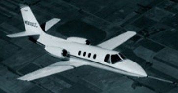
Announced in 7 October 1968, Cessna’s first business jet, the FanJet 500, made its maiden flight on September 15, 1969. Renamed the Model 500 Citation shortly after the first flight, the eight-seat Model 500 has an overall configuration similar to that of earlier Cessna twins except for its powerplant installation. This featured two 990kg Pratt & Whitney Canada JT15D-1 turbofans, mounted in pods on each side of the rear fuselage just aft of the wing trailing edge.
First flown on 15 September 1969, development flying resulted in a number of changes, and it was not until 1972 that initial deliveries were made. The Citation received FAR Part 25 certification in September 1971 and the first Citation business jet was delivered to Levitz Furniture Corp in 1972.
Cessna 500 Citation – the 50th built
In 1976 deliveries began of an improved Model 501 Citation I with increased wing span and similarly rated but improved JT15D-1A engines. This was followed soon after by the Citation 1/SP version certificated for single-pilot operation. This had JT15D-1A engines, thrust reversers, and a slightly increased wingspan. When production ceased in June 1985, 691 Citation Is had been delivered.
CE-500 Citation I Engines: 2 x P&W JT15D-1A, 2,200 lbs thrust. Seats: 7/8. Length: 43.5 ft. Height: 14.3 ft. Wingspan: 47.1 ft. Wing area: 279 sq.ft. Wing aspect ratio: 7.8. Maximum ramp weight: 12,000 lbs. Maximum takeoff weight: 11,850 lbs. Standard empty weight: 6605 lbs. Maximum useful load: 5395 lbs. Zero-fuel weight: 9500 lbs. Maximum landing weight: 11,350 lbs. Wing loading: 42.5 lbs/sq.ft. Power loading: 2.7 lbs/lb. Maximum usable fuel: 3807 lbs/564 USG. Best rate of climb: 2680 fpm. Certificated ceiling: 41,000 ft. Max pressurisation differential: 8.5 psi. 8000 ft cabin alt @: 41,000 ft. Maximum single-engine rate of climb: 800 fpm @ 108 kts. Single-engine climb gradient: 425 ft/nm. Single-engine ceiling: 21,000 ft. Maximum speed: 352 kts. Max range: 1,326 nm. Normal cruise @ 33,000ft: 352 kts. Fuel flow @ normal cruise: 967 pph. Stalling speed clean: 93 kts. Stalling speed gear/flaps down: 82 kts. Balanced field length: 2,930 ft. Turbulent-air penetration speed: 183 kts. Seats: 10. Takeoff distance (50 ft) 3,275 ft. Landing distance (50 ft) 2,300 ft
A four seat development of the T 37A CE airframe, the forward fuselage redesigned to take four persons in pressurised cabin. Entry to cabin via large door in starboard side. Rear seats removable for cargo or special mission equipment.
Powered by two Continental C 356 9 turbojets, the prototype (N34267 serial number 627) first flew September 1959 and later modified with bulbous radar nose. One only built.
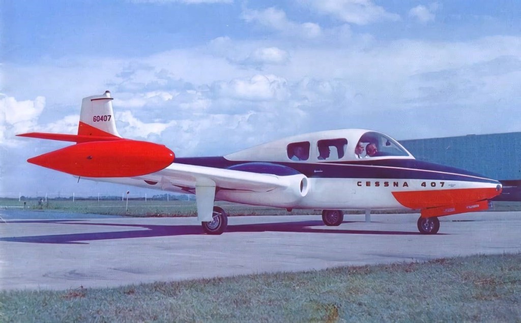
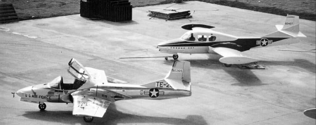
By utilizing many of the same components and tooling as the T-37, much of the necessary development work could be avoided. Building a full-scale wooden mock-up and beginning construction of the first prototype, the marketing group began a sales tour, pitching the concept at various locations around the U.S.
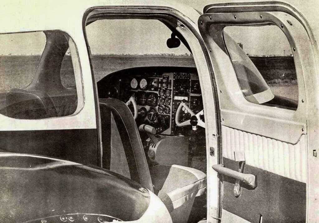
Outwardly similar to the T-37, the 407 utilized the same tail section and wing as the jet trainer but repositioned the engine nacelles 9 inches outward to create more internal space. The cabin utilized this additional space to accommodate four passengers and their baggage. Occupants could easily step into the low-slung cabin without the need for separate steps or ladders, a welcome change from the MS.760, which required occupants to climb a stepladder and clamber into the cockpit from above.
The 407 would incorporate a pressurized cabin for passenger comfort. This helped to enable a rather impressive service ceiling of 46,400 feet. At a more typical cruising altitude of 35,000 feet, the 407’s cabin altitude would have been maintained at a reasonable 8,000 feet.
With a 4,657-pound empty weight and 9,300-pound gross weight, the team boasted a range of 1,380 nm and a maximum level speed of 423 knots. The stall speed was listed as a relatively low 84 knots, making the jet capable of accessing runways of around 3,000 feet in length.
Ultimately, the 407 was not to be. The mock-up pictured was, in fact, a T-37 with a wooden cabin section. And while construction of actual cabin sections was underway, the entire 407 project was abandoned in favor of the Citation family, the first of which flew in 1969. Interestingly, the FAA registry shows that Cessna registered a 407 as N34267.
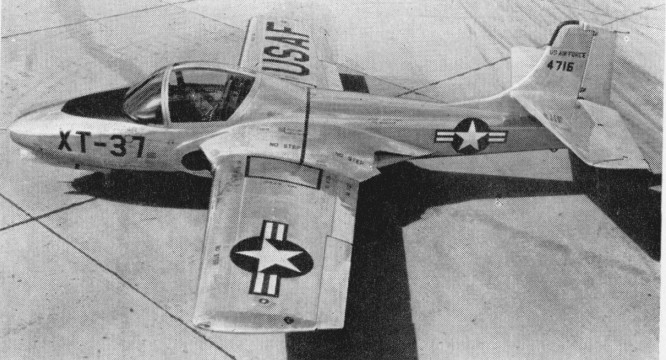
Late in 1952 the USAF formulated a requirement for a jet trainer which would economically permit student indoctrination at an early stage in the training curriculum. Specified design requirements included an empty weight of 4,000 lb (1814 kg) in order to limit both cost and complexity of the aircraft; the ability to undertake twenty take offs and landings within a two hour period; flight handling characteristics matching those of the most modern operational fighters; a 35,000 ft (10668 m) cruise ceiling with sufficient high altitude manoeuvrability to wholly orientate students, and a maximum traffic pattern speed of 113 knots (209 km/h) to assure good low speed handling characteristics. Side by side seating for the student and instructor was favoured. The Marbore II became the Continental J69 and the Cessna company designed their Model 318 around two J69s. This aircraft was a basic jet trainer. In the ensuing design contest, Cessna’s Model 318 was designated the victor early in 1953, and as XT 37s, three prototypes (54 716 to 54 718) were ordered.
The first of these flew on October 12, 1954, (piloted by Bob Hagen), powered by two Continental YJ69 T 9s (licence built Turbomeca Mabore IIs) with 920 lbf (4.1 kN) thrust each, by which time its manufacturers had been awarded a $5 million contract for eleven pre production T 37A trainers (54 2729 to 54 2739), the first of which flew on September 27, 1955. One of the XT-37 prototypes was lost in a flat spin; the pilot baled successfully. Some strengthening of the wing centre section was found to be necessary, the cockpit layout had to be revised, and field trials with the pre production machines were accompanied by minor teething troubles, among these being the fuel system of the Continental J69 turbojets licence built Turbomeca Marbore IIs, but these were soon overcome, and by the early spring of 1956, contracts had been placed for twenty (55 4302 to 55 4321) and 127 (56 3464 to 56 3590) production T 37A trainers, a contract for a further 123 machines (57 2230 to 57 2352) following shortly afterwards, and the 200th T 37A rolling off the assembly line on July 23, 1958. 534 were built under successive contracts, but were slow in entering service as a result of the need for a number of changes and modifications before they were considered acceptable for training purposes.
The first T-37A was completed in September 1955 and flew later that year. The T-37A was delivered to the U.S. Air Force beginning in June 1956. In the spring of 1957, the first training courses on the T 37A had begun at Waco, Texas, the first class of twenty students receiving 150 hours on the new jet trainer after forty hours on the piston engined Beech T 34A primary trainer. The second group of students at Waco had only twenty hours on the T 34A as the next stage in evolving an all jet curriculum.
In April 1961 all-through jet training was initiated, the pupil flying from the very beginning of his training on T-37 aircraft which had a speed range of 138-684km/h. No catastrophic accident rate resulted, as had been feared by many, but one point which had not been fully considered was the much higher training cost using jet aircraft. There is inevitably a varying pupil rejection rate at the end of primary training, and it was decided in 1964 to revert to light piston-engine trainers, which are much cheaper to operate, for this primary phase, so that T-37 pupils were those left after the first weeding-out.
The T 37A was powered by the 920 lb.s.t. (417 kgp) J69 T 9 turbojet, but during 1959, after the delivery of 416 aircraft of this type, production switched to the T 37B with 1,025 lb.s.t. (465 kgp) J69 T 25 turbojets, and new Onini and UHF equipment, the first of the improved trainers being accepted by the USAF on November 6, 1959. Subsequently, all T 37As passed through a modification programme to bring them up to ‘B’ standards.
For the training role, Cessna chose straight wings, twin wing root mounted engines and side by side seating. The original 417 kg (920 lb) thrust Continental J69 9 engines, built under licence from Turbomeca, were not calculated to make the American type a startling performer.
The T 37B is basically a low wing cantilever monoplane of all metal construction, and has its twin J69 T 25 turbojets mounted in the thickened wing roots, their inboard location creating a negligible change in directional control with one engine inoperative, and facilitating the demonstration of single engine procedures. A single stage, centrifugal compressor engine, the J69 T 25 has a fully automatic altitude compensating fuel control, and the two power plants draw their fuel from the main fuselage tank immediately aft of the cockpit, this being fed from six inter connecting rubber cell fuel tanks in each wing, the total usable capacity of these being 257 Imp. gal. (1 168 lt). Engine driven pumps and submerged booster pumps drive the automatic fuel transfer system, but in the event of a fuel proportioner or electrical system malfunction, fuel is automatically supplied to the engines by the gravity system.
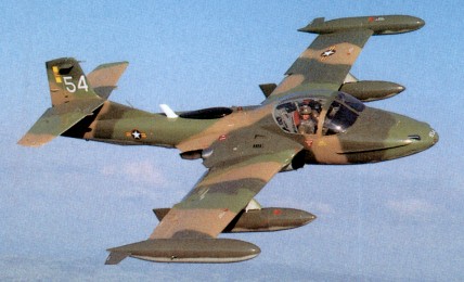
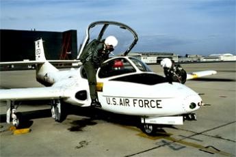
The low ‘sit’ of the T 37B on the ground eliminates the need for cockpit entrance ladders, flush steps in the fuselage 24 in (61 cm) above the ground providing easy entrance from either side of the aircraft. The cockpit itself is ideally situated, well forward of the wing, and, with the backward folding, jettisonable clam shell type canopy offers excellent visibility. The panel itself is a relatively simple and straightforward approach to current requirements. The primary instruments are duplicated for instructor and student, all instruments may be monitored, and all operating controls and switches are easily accessible from either seat. Positioned to port on the student’s side are the navigational and flight instruments, including directional and attitude indicators, altimeter, turn and bank, rate of climb and airspeed indicators, and course indicator. In front of the instructor on the starboard side but within reach of the student are the radio controls, circuit breaker, etc., and the engine instruments mounted over the central quadrant include tachometers, fuel flow and exhaust temperature indicators, fuel and oil pressure gauges, loadmeters and accelerometer. The stick grips and throttle quadrants are of fighter type. A 1,500 psi (105.5 kg/sq.cm) hydraulic system is installed. Two engine driven, constant displacement hydraulic pumps are used to drive the landing gear and doors, speed brake and thrust attenuators, nosewheel steering system, flaps and stall spoilers. The hydraulically operated brakes are independent of this system. The electrical system comprises two 200 amp. starter generators, one 24 volt, 36 amp hour battery and associated control equipment. No ancillary starting equipment is necessary, the battery being sufficient to provide engine starts for all normal training operations. Structurally, the T 37B comprises a semi monocoque fuselage, a two spar aluminium alloy wing of NACA 2418 section at the root and NACA 2412 section at the tip, and a normal cantilever monoplane type tail assembly of which the fin is integral with the fuselage, and the tailplane is mounted one third of the way up the fin. Hydraulically operated high lift slotted flaps with a total area of 15.1 sq ft (1.4 sq.m) are mounted inboard of the ailerons which have a total area of 11.3 sq. ft. (1.05 sq.m), and all movable tail surfaces have electrically operated trim tabs. Because of its low drag characteristics, an hydraulically actuated speed brake is located on the underside of the fuselage nose section, aft of the nosewheel well. This brake works in con¬junction with thrust attenuators which deflect the exhaust blast and permit higher rpm during landing approaches. When the attenuators are extended, the resultant effective thrust is reduced by more than forty per cent. Both attenuators and speed brake are controlled by the speed brake switch when the throttles are below seventy per cent rpm. The thrust attenuators automatically retract when the throttles are advanced above seventy per cent rpm. The undercarriage has two extension systems, the primary system being hydraulically actuated and the secondary system being pneumatically powered. The wheel brakes are, as previously mentioned, operated by a separate hydraulic system controlled by dual rudder and brake pedals, and the wide track of the main members (14 ft 0.5 in. 4.28 m) results in an unusually high degree of ground stability. The T 37B demonstrates good stability in all configurations and conditions of flight. Extremely effective control surfaces result in instant response, and light forces, well balanced between the three controls, make all manoeuvres easily co ordinated. Spins are mild and recovery by use of standard procedure is positive. The excellent stall characteristics are well defined with lateral control effective at all times, and good stall warning is provided for all flight configurations. Landings are accomplished equally well from either scat, and no abrupt pitch or directional trim change results when power is added for another circuit of the field. These characteristics are ideal for a training aircraft but they also result in an excellent weapons platform, and supplanting the T 37B trainer on the Wichita assembly line as the T 37C which has underwing attachment points for offensive stores or drop tanks and is intended primarily for supply to the smaller nations militarily aligned with the USA. With a gun sight mounted in the cockpit, underwing racks can carry bombs or rocket, gun or photographic pods for internal security duties, and the T 37C served with such coun¬tries as Portugal (30) and Vietnam. Mission range may be increased to more than 1,100 nautical miles (2 040 km) by the addition of wingtip tanks which, each containing 54 Imp gal. (246 lt), increase the total fuel capacity to 366 Imp gal. (1664 lt). Fuel is transferred from the tip tanks to the wing tanks by inline booster pumps, utilizing the existing internal fuel system, and provision is made for jettisoning. When production ended in 1977 a total of 1,268 T-37s had been built for the USAF and for export. During 1962 two Cessna T-37B trainers were evaluated by the USAF’s Special Air Warfare Center to consider their suitability for deployment in the counter-insurgency (COIN) role. These were first tested with their original powerplant of two 465kg thrust Continental J69-T-25 turbojets, at a take-off weight of 3946kg, almost 33% above the normal maximum take-off weight. Subsequently the airframes were modified to accept two 1089kg thrust General Electric J85-GE-5 turbojets. This increase in power made it possible for the aircraft, then designated YAT-37D, to be flown at steadily increasing take-off weights until a safe upper limit of 6350kg was reached. After successful trials Cessna were requested to convert 39 T-37B trainers from the production line to a light-strike configuration, a contract being awarded in 1966. Designated A 37A, they were delivered, only being withdrawn from service ten years later in 1974. The new model was based on the earlier experiments with the two YAT-37Ds, and equipped with eight underwing hard-points, provided with wingtip tanks to increase fuel capacity and powered by derated General Electric J85-GE-5 turbojets. Delivery to the USAF began on 2 May 1967, and during the latter half of that year a squadron numbering 25 of these aircraft underwent a four-month operational evaluation in South Vietnam. Following this investigation they were transferred for operational duty with the 604th Air Commando Squadron at Bien Hoa, and in 1970 they were assigned to the South Vietnamese air force. This led to the conversion of a number of T 37Bs to A 37A Dragonfly status for operational evaluation in Vietnam and followed with development of the much more dedicated A 37B. Production of 577 started in 1968, featuring the General Electric J85 turbojet, airframe stressed to 6g, much increased fuel capacity and eight underwing hardpoints. Various improvements to the avionics, upgrading of the turbines, the addition of wingtip fuel tanks, and provision for weapons saw the trainer develop into an attack version, and new aircraft were still being delivered for export in late 1977. Featuring side by side seating, the lightjet powered by two General Electric turbojets each rated in excess of 2800 lb static thrust had a range of some 1050 miles on a tankage of 1100 litres. Armed with a mini gun in the nose and with four pylons on each wing for ordinance and stores, the A 37 could feature a typical delivery of four 8701b bombs, two 600 lb bombs and two 500 lb bombs. A load could consist of an assortment of fire bombs, demolition bombs, canister clusters, flares or rockets. The aircraft could, it is claimed, carry their own weight in stores. During this period, Cessna had built the Model 318E prototype of a purpose-designated light-strike aircraft based on the T-37 and this flew for the first time in September 1967. The initial production batch of this A-37B was started quickly enough for the first deliveries to begin in May 1968. The A-37B differed in construction from the prototype YAT-37D, its airframe stressed for 6g loading, maximum internal fuel capacity increased to 1920 litres with the ability to carry four auxiliary tanks having a combined capacity of 1516 litres, and with provision for flight-refuelling. The engines were changed to two General Electric J85-GE-17A turbojets of 2585 kg (5700 lb) total installed thrust. The tip tanks became standard, a GAU-2B/A 7.62mm Minigun was installed, and eight underwing hardpoints. The two inner of these can each carry 395 kg (870 lb), the intermediate ones 272 kg (600 lb) and the outers up to 227 kg (500 lb) although the maximum weapon load is 2576 kg (5680 lb) with a maximum takeoff weight of 6350 kg (14000 lb). For the assessment of results both gun and strike cameras were carried, and some armour protection for the crew of two was provided by the inclusion of layered nylon flak-curtains installed around the cockpit. The avionics is limited to comprehensive but basic navigation/communications and a non computing gunsight. A Forward Air Control variant existed as the OA-37B. By the time production ended in 1977, 577 A-37Bs had been delivered. The Cessna Model 318E Dragonfly (A-37B) is equipped with two General Electric J85-17A turbojets, giving it almost double the takeoff power (each rated in excess of 2,800 lbs static thrust), and subsequently double the takeoff weight, over that of the T-37. Increasing the number of and strengthening the hard points, enables the A-37B to carry close to its own empty weight in armament (around 5000 lb).
The last T-37B was officially retired from active USAF service on 31 July 2009
The US Government supplied 254 Cessna A37B Dragonfly’s to the Vietnam Air Force (VNAF) during the Vietnam War. After the fall of South Vietnam in 1975, ninety-five VNAF A37B aircraft were captured and incorporated into the Vietnamese People’s Air Force. Many were transferred to the US Air National Guard. More than 600 were delivered at home and abroad, including sales to Brazil, Chile, Guatemala, Honduras, Peru, Thailand.
Military Users: (All models) Brazil, Cambodia, Chile, Columbia, Ecuador, Guatemala, Greece, Honduras, South Korea, Pakistan, Peru, Portugal, Thailand, Turkey, South Vietnam, Vietnam, USAF (and Luftwaffe via US training programme).
XT 37 CE Three prototypes of the Model 318, first flown October 12, 1954. Powered by two Continental YJ69 T 9s (licence built Turbomeca Mabore IIs) with 920 lbf (4.1 kN) thrust each.
T 37 CE Pre production batch of eleven airframes. All subsequently redesignated as T 37A CEs.
T 37A CE Cessna Model 318A, production standard. Two Continental T69 T¬9s. Production came to 444 units, survivors up graded to T 37W CE. Single example to JT 37A CE for special test. T 37 universally known as the Tweety Bird or Tweet in USAF service.
T 37B CE Further improved production standard, improved radio/navigation installation and J69 T 25s. Model 318B, 552 built.
T 37C CE Version of T 37B CE for Military Assistance Program countries. Provision for underwing pylons and tip tanks optional. 198 built.
YAT 37D CE Two T 37C CEs converted to counter insurgency aircraft with six underwing hardpoints and two General Electric J85 GE 5s. Both redesignated YA 37A CE. Cessna Model 318D.
A 37A CE Dragonfly ‘Production’ version of YA 37A CE with eight underwing hardpoints and 7.62mm Minigun in nose. 39 T 37B CE converted.
A 37B CE Dragonfly New build version, as A 37A CE but with J85 GE 17A, increased fuel, provision for in flight refuelling and strengthened airframe. 577 built of which one was termed YA 37B CE for development work.
OA 37B CE Dragonfly At least 122 A 37Bs redesignated for use by Air National Guard units in the Forward Air Controller role.
Specifications:
T 37A Engines: Two Continental T69 T¬9 Wing span: 33.78 ft ( 10.3 m). Overall length: 29.25 ft ( 8.9 m). Height: 9.17 ft ( 2.8 m). Wing area: 183.9 sq.ft ( 17.1 sq.m). Wing aspect ratio: 6.20. Empty wt: 4056 lb ( 1841 kg). Normal T/O wt: 6574 lb ( 2984 kg). MTOW: 6574 lb ( 2984 kg). Internal fuel cap: 257 Imp.Gal. (1168 lt). External fuel cap: 108 Imp.Gal. (490 lt). Wing loading: 35.7 lb/sq.ft ( 174 kg/sq.m). Pwr loading: 3.7 lb/lbst ( 3.7 kg/kgst). Max speed: 452 mph ( 727 kph). Initial ROC: 3000 fpm ( 15 m/sec). TO dist 50 ft: 2025 ft ( 617 m). Range: 935 sm ( 1500 km).
T-37A Engines: 2 x Continental J69-T-15, 920 lb Wingspan: 33 ft Length: 27 ft 1 in Height: 8 ft 9.25 in Wing area: 181.8 sq.ft Empty weight: 3116 lb Loaded weight: 5600 lb Max speed: 393 mph at 35,000 ft Cruise: 310 mph ROC: 3000 fpm Service ceiling: 39,800 ft Max range: 935 mi
T 37B Engine: 2 x Continental J69 T 25 turbojets, 1,025 lbs.t. (465 kgp). Span, 33 ft 9.5 in (10.3 m) Length, 29 ft 3 in (8.93 m) Height: 9.19ft (2.80m) Wing area, 183.9 sq.ft (17.09 sq.m). Gross weight: 6,574 lb 2 982 kg Empty wt: 4,056 lb (1840 kg). Take off dist to 50 ft. (15 m): 2,025 ft. (617 m). ROC S/L Military RPM: 3370 fpm (17 m/sec). Service Ceiling Military RPM: 38,700 ft (11 796 m). Single engine Service Ceiling ½ Fuel Military RPM: 25,000 ft (7 620 m). Cruise speed Normal rated power, ½ fuel at 35,000 ft (10 668 m): 320 kts (593 kph). Max speed ½ fuel Military RPM at 20,000 ft (6 096 m): 369 kts (684 kph) Range at 35,000 ft (10 668 m) at 289 kts (535 kph): 692 nm (1282 km). Max range 5% reserve at 35,000 ft (10 668 m) at 289 kts (535 kph): 809 nm (1 499 km). Range at normal RPM with 5% reserves at 35,000 ft (10 668 m) at 313 kts (580 kph): 755 nm (1390 km). Landing Distance from 50ft (15 m): 2,600 ft (792 m). Stalling speed gross weight, SL: 74 kts (137 kph).
T-38C – Engine: 2 x Continental J69 T 25 turbojets, 1,025 lbs.t. (465 kgp). Span, 33 ft 9.5 in (10.3 m) Length, 29 ft 3 in (8.93 m) Height: 9.19ft (2.80m) Wing area, 183.9 sq.ft (17.09 sq.m). Armament: 2 x 250lb Iron Bombs Rate-of-Climb: 3,370ft/min (1,027m/min) Service Ceiling: 39,199ft (11,948m; 7.4miles) Accommodation: 2 Hardpoints: 2
YAT 37D Engine: 2 x General Electric J85 GE 5 turbojet, 2,400 lb.s.t. (1 088.6 kgp). Gross weight: 10,500 lb. (4 763 kg). Take off dist: 1,000 1,700 ft (305 518 m). Ordnance: 3,000 lb. (1361 kg). Max speed: 475 mph (764 km/h) clean Max speed: 320 mph (515 km/h) max external ordnance and wingtip tanks.
A 37 Dragonfly Engine: 2 x Continental J69-T-25, 4562 N / 465 kp Length: 29.298 ft / 8.93 m Height: 9.35 ft / 2.85 m Wingspan: 33.793 ft / 10.3 m Max take off weight: 6401.1 lb / 2903.0 kg Max. speed: 370 kts / 686 km/h Service ceiling: 38714 ft / 11800 m Range: 1150 nm / 2130 km Crew: 2
Cessna A37B Dragonfly Engines: Two General Electric J85-17A Axial Flow turbojets, 2,850 lbs (1293kg) Wingspan: 10.93 m / 35 ft 10 in over tip tanks Wing Area: 193.5 sq. ft / 17.98 sq. m Length: 8.62 m / 28 ft 3 in Height: 2.71 m / 8 ft 11 in Empty weight: 6,254 lb / 2,843 kg Maximum Takeoff weight: 14,000 lb / 6,364 kg Maximum landing weight: 6350 kg (14 000 lb) Wing Tank Capacity: 2 x 83 Imperial Gallons / 376 Litres / 99 U.S. Gallons Fuselage Tank Capacity: 2 x 66 Imperial Gallons / 299 Litres / 79 U.S. Gallons Wingtip Tank Capacity: 2 x 75 Imperial Gallons / 341 Litres / 90 U.S. Gallons Pylon Tank Capacity: 4 x 81 Imperial Gallons / 367 Litres / 97 U.S. Gallons Maximum Speed: 420 knots / 483 mph / 778 km/h Cruise Speed: 265 knots / 305 mph / 491 km/h Cruise at 25,000 ft: 489 mph (787 km/h). Rate-of-Climb: 6,990ft/min (2,131m/min) Service Ceiling: 41,762ft / 12,729m Range w/max.fuel: 1629 km / 1012 miles Range w/max.payload: 740 km / 460 miles Take off run: 1740 ft. Landing dist: 1710 feet. Armament: One GAU-2B/A 7.62mm Minigun Hardpoints: 8
Designed by Construcciones Aeronauticas SA with collaboration from MBB and Northrop, the prototype of the CASA C 101 Aviojet made its maiden flight on 27 June 1977. A tandem two seat basic and advanced trainer with light attack capability, the C-101 is powered by a Garrett TFE731 2 25 non afterburning turbofan. The Aviojet features six pylons and a gun pack under the rear seat with either a single 30 mm DEFA cannon or two 12.7 mm machine guns. The Garrett AiResearch TFE731 turbofan combines with a large integral fuel capacity to provide a seven hour endurance
Spain’s CASA C 101 Aviojet has the Spanish air force designation E.25, entering service in 1980. An armed version has been exported to Honduras (4) and Chile (60). Four versions of the Aviojet single-turbofan tandem-seat trainer have been built. The C.101EB was the initial trainer variant for the Spanish Air Force, production of which was completed during 1985.
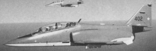
An export trainer version, the C.101BB (operated by Chile as the T-36 Halcon), has an uprated engine and provision for arma¬ment on underwing hardpoints, while the C.101CC, (operated by Chile as the A-36 Halcon), is a light-attack aircraft with a further uprated engine offering 19.l3kN thrust. Weap¬ons options for the C.101CC include an under-fuselage 30mm DEFA cannon pod, rocket and gun pods underwing, together with bombs and AGM-65 Maverick ASMs.
The C-101BB armed export model differs from the C-101EB primarily in having a Garrett AiResearch TFE 731-3-1J turbofan rated at 3700 lb / 1658 kg rather than the 3500 lb / 1588 kg TFE 731-2-2J, and provision for interchangeable ventral packs containing either one 30mm DEFA 553 cannon or two 12.7mm M3 machine guns, six underwing pylons, an optical weapons sight and an armament control system. The -3 turbofan was first flown in the second Aviojet prototype in February 1981. Announced in 1984, the C.101DD enhanced training version first flew on May 20, 1985. The CC.101DD Aviojet has the more powerful engine of the C.101CC combined with a major avionics upgrade which includes a Ferranti headup display weapons aiming computer, a Ferranti FIN 1100 altitude and heading reference system, a radar warning receiver, and flare/chaff dispensing pods. A reconnaissance pack and laser target designator are optional for both the C.101CC and DD versions.
C-101 Engine: 1 x Garrett TFE731-2-25 turbofan Max Take-off weight: 5600 kg / 12346 lb Empty weight: 3350 kg / 7386 lb Wingspan: 10.6 m / 34 ft 9 in Length: 12.25 m / 40 ft 2 in Height: 4.25 m / 13 ft 11 in Wing area: 20.0 sq.m / 215.28 sq ft Max. speed: 685 km/h / 426 mph Ceiling: 12500 m / 41000 ft Range w/max.fuel: 3800 km / 2361 miles Range w/max.payload: 370 km / 230 miles Armament: 1 x 30mm cannon, 2000kg of weapons Crew: 1-2
C.101CC Aviojet Engine: 1 x Garrett TFE731-5. Installed thrust: 19.2 kN (21kN). Span: 10.6 m. Length: 12.5 m. Wing area: 20 sq.m Empty wt: 3340 kg. MTOW: 6300 kg. Warload: 2250 kg. Max speed: 769 kph. Initial ROC: 1500 m / min. Ceiling: 12,800 m. T/O run: 560 m. Ldg run: 480 m. Fuel internal: 2410 lt. Range/Endurance: 3700 km / 7 hr. Combat radius lo-lo-hi: 520 km. Armament: 1 x 30 mm or 2 x .5 in. Hardpoints: 6.
CASA C-101EB Aviojet Engine: 1 x Garrett TFE731-2-2J turbofan, 3,550lb thrust. Length: 40.19ft (12.25m) Width: 34.78ft (10.60m) Height: 13.94ft (4.25m) Maximum Speed: 478mph (770kmh; 416kts) Maximum Range: 2,485miles (4,000km) Rate-of-Climb: 4,900ft/min (1,494m/min) Service Ceiling: 41,010ft (12,500m; 7.8miles) Armament: 1 x 30mm DEFA cannon or 2 x 12.7mm M3 machine guns. Up to 4,890lbs of external ordnance Accommodation: 2 Hardpoints: 6 Empty Weight: 8,378lbs (3,800kg) Maximum Take-Off Weight: 12,346lbs (5,600kg)
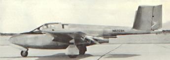
In the early fifties Harold Dale played with the idea to design the ideal jet trainer: seating trainee and instructor side-by-side in front of the wing for clear visibility all around. It should have a slow landing speed and a comfortable cruising speed of 350 mph. The plane Harold had in mind was a mid-wing cantilever monoplane of aluminium alloy structure, with slotted flaps, leading edge intake ducts, semi-monocoque fuselage, upwards opening doors, butterfly tail unit and retractable tricycle landing gear.
Harold Dale was a project engineer with North American working on the F-100, so his ideal plane had to be designed in the spare time. He had assistance from his wife Eleanor who also had an engineering degree, handling much of the mathematics, administration, etc.
The name chosen was the WEEJET 800 (WE=Harold and Eleanor), the 800 meaning the power class of the licence built Turboméca Marboré II engine of 880 lb thrust.
In February 1952 Dale Air-Engineering (Torrance, California) and the WEEJET 800 were official registered and the first material was submitted to the CAA West Region Administration. It was the first jet aircraft in the small plane field submitted to the CAA, who followed every phase of the two and a half years of design and evaluated all data during development.
In 1954 a local aircraft parts manufacturer (Carma Manufacturing Co) heard of the design and got involved in the project in two ways: he supplied the hydraulic shock absorber struts and offered to built the aircraft in his plant in Tucson, Arizona. Now it became feasible to produce and market the aircraft. Construction started at Tucson in the second half of 1954 and five people worked one and a half years on it.
The prototype (N8209H) conducted its 20 minutes first flight on Good Friday March 30, 1956, with Harold Dale at the controls. During the following weeks further test flights were made by another pilot, except for the spin tests, these were performed by USAF-pilot Doneby; the aircraft handled and performed well.
During 1956 the US Navy had become interested in jet trainers and the WEEJET was to be in their evaluation. Therefore all data had to be available before the end of the month and the aircraft was to be flown to Patuxtent, Maryland on April 29. On April 28 1956 disaster struck: during the final spin test the pilot inadvertently activated the trim tab into full nose-down position. The pilot lost control while trying to recover and had to bail out, the aircraft crashed and burned. Later data was found thrown clear of the wreckage, showing the spin tests were a complete success.
All following data was issued on April 25, 1956 in a proposal to the US Navy for the production version. The designation was Carma WEEJET TRAINER.
Carma VT-1 WEEJET Type: Two side by side seat primary jet trainer Engine: Continental J69-T-9 (Marbore II), 920 lb (417 kg) s.t. Wingspan: 28 ft 0 in (8.53 m) Length: 24 ft 6 in (7.47 m) Height: 6 ft 8 in (2.03 m) Wing area: 150 sq.ft (13.94 sq.m) Empty Wt: 2,481 lb (1,125 kg) Max T/O Wt: 4,541 lb (2,060 kg) Max speed: 334 mph (537 km/h) at 15,000 ft (4,570 m) Cruise speed: 208 mph at 25,000 ft Max climb: 2,200 ft (670 m)/min Service ceiling: 35,000 ft (10,670 m) Endurance: 1.72 hr at sea level
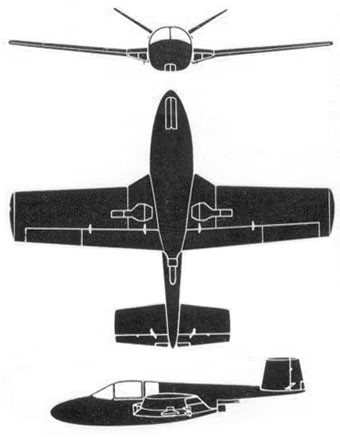
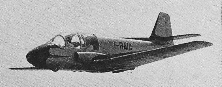
The F.5 tandem two-seat training monoplane designed by Stelio Frati was the first light jet aircraft of Italian design, flying for the first time on 20 May 1952.
Powered by a 330 lb Turbomeca Palas turbojet, the F.5 is of all wood construction, with dual controls and jettisonable canopies. A retractable nosewheel undercarriage is fitted.
Engine: 330 lb Turbomeca Palas Wing area: 107.63 sq.ft Wing span: 25 ft 8 in Length: 21 ft 7.5 on Empty weight: 1032 lb Loaded weight: 1650 lb Max speed: 224 mph at SL / 242 mph at altitude Time to 16,400 ft: 23 min Service ceiling: 23,300 ft
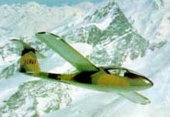
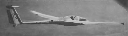
Based on the experience gained with the Calif, the C- 22J was developed. The C-22 J Caproncino is a side by side two-seater equipped with two Microturbo engines.
The first C- 22J has made its first flight 21 July 1980. It was presented static at the Salon du Bourget 1981 and flying at Farnborough in 1984, where it was flown by Colonel Paolo Barberis, former commander of the Italian nationnale patrol “Frecce Tricolori”.
3 examples were built. Sale price: $300 000 – 375 000
No. 001 I-CAVJ Museo Gianni dell’Aeronautica Caproni, Trento, Italy
No. 002 I-GIAC
No. 003 I-CAVT Museum “Volandia” Milan, Italy
Wingspan: 10 m Length: 6.188 m Height: 1.88 m Wing area: 8.75 m² Max level speed: 530 km.h Max speed: 700 km.h Endurance: 3 hr 18 min External load: 200 kg
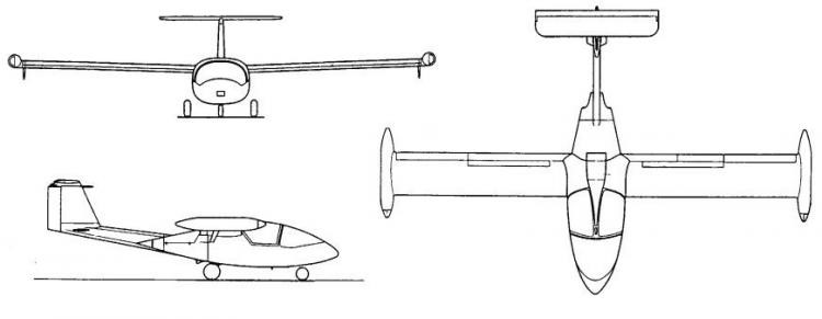
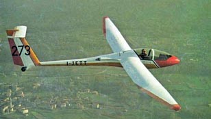
Designed by G. Ferrarin and L. Sonzio, the original A-21, the prototype of which made its first flight on 23 November 1970, was a high performance two-seat version of the A-14, from which it differed in having a slightly longer fuselage widened to accommodate two in luxurious side-by-side seating.
This version was succeeded by the A-21S, which held four world records for two-seaters; among these is the Class D2 speed record for women over a 300km closed circuit, set up on 18 August 1974 by Adele Orsi and Franca Bellingeri in an A-21S at a speed of 60.73mph.
Caproni Vizzola Calif A-21 S
The cantilever mid wings have a wide constant chord centre section and tapered trapezoid outer panels, and are all-metal; the three-piece all-metal main spar is supplemented by two auxiliary spars in the centre section and one in each outer panel, the downturned wing tips being of glassfibre. The trailing edge flaps/spoilers can act as air brakes when deflected to 89 downwards, and as camber-changing surfaces between ±8°; the plain ailerons are differentially-operated. The forward fuselage is a glassfibre/foam plastics semimonocoque structure with a load-carrying light alloy frame, and the rear fuselage is a thin boom of all metal stressed skin construction. The distinctive high aspect ratio fin and rudder is all-metal, and has the all-moving metal tailplane and elevator, which both have glassfibre tips, mounted on top; the tailplane trim is spring-adjusted. The mechanically retractable twin main wheels have rubber-incompression shock absorbers and a brake, and there is a fixed steerable tailwheel, as well as a small wheel in each downturned wing tip. The two pilots have dual controls under a rearward-sliding two piece canopy, and sit in luxury seating equivalent to the best light plane standards.
Over 100 A-21S Califs had been built, production of a third batch of 54 being ordered by January 1980.
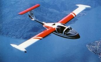
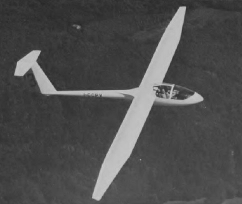
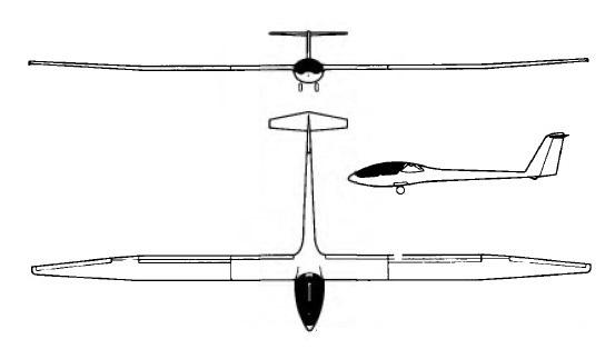
With 66.9 feet of wingspan, the A-21SJ is the only production turbojet-powered sailplane in the world. It offers side-by-side seating and all-metal construction. The engine retracts into the fuselage just aft of the cockpit. Cruise speed is 124 mph and climb is 945 fpm. On 36 gallons of fuel, range is about 217 miles, with a ceiling of 43,300 feet. Takeoff run requires only 1,181 feet. Up to 90 percent of the parts between the sailplane and the motorglider are common to both, so the glider can be transformed easily into a jet glider, even in retrofit. The landing gear for both aircraft features dual main gear that retract into the undercarriage. Two small wheels are built into the wingtips. The wing is all-metal with a single spar, stressed skin, and fiberglass tips; the wing is fitted with top-hinged, differentially operated ailerons plus lower-hinged, aerodynamically balanced flaps/spoilers. The fuselage has a monocoque forward section of fiberglass with a load-carrying lightweight alloy structure. The tailboom is an all-metal stressed-skin unit ending in an all-metal single-spar tailplane. Caproni (which built its first glider in 1908 at Vizzola Ticino, Italy) produced the first A-21 (designed by Carlo Ferrarin and Livio Sonzio) in 1970, and within two years had collected four world multi-place sailplane speed and distance records with it. A 2-place all-metal ship with a fiberglass forward fuselage, the A-21 was followed into production by the slightly improved S model. The ship features a roomy side-by-side cockpit and widely spaced retractable twin landing wheels. Aft-hinged brakes on the lower surface, and these, with large flaps (which deflect to +89 degrees) limit speed in a vertical five to 188 kph / 102 kt / 117 mph. The T-tail is all moving. A steerable tail wheel and water ballast were optional. The Calif A-21S was produced im a small-series produced (6 aircraft) at the Gomolzig Flugzeug- und Maschinenbau. The Italian construction offers good performance (comparable to Janus C) and good flying characteristics, giving the aircraft a broad range of applications reaching from advanced training and guest flights up to performance flights. Only for competition flights in the double-seater class, it is exceeding the 20-meter definition by a few centimeters. The A- 21S cost approximately 20000 Marks less than a Duo Discus and features a fixed tailplane. The A-21JA self launch jet model is a 2 place, side by side all metal sailplane. Forward fuselage is glass fibre. Dual, manually retracting undercarriage. Fixed tail wheel. Rudder pedals adjustable. Both seats adjustable. Extremely powerful trailing edge flap / brakes. Flaps have a thermal setting, cruise setting and fully variable down for landing. Automatic control hook up. No manufacturers fatigue life limit. A very high quality structure, built by an aircraft manufacturer not a glider manufacturer. It was well and truly “state of the art” in 1974.
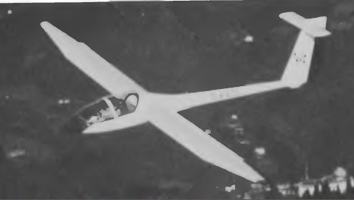
First flying in late January 1972, the A21 J jet version added a SERMEL TR18 100 kp thrust (220 lb) jet engine. The span was reduced from 22.87 to 20 m, and overall length increased from 7.27 to 8m. The tare weight (equipped) is reduced from 484 to 434 kg. The engine is mounted in the lower part of the fuselage, behind the seat, the ejection of gas under the fuselage. The volume of wing and fuselage tanks hold 160 litres of kerosene. The engine is started with a compressed air bottle.
A21 J
In 1976 the first prototype of the A- 21J was purchased by Lockheed to be used in a research program conducted in cooperation with the Mississippi State University. The experiments concerned inter alia the effects of wind, dust, insects and rain on some wing sections, as well as measures and vortex noise rappport the fuselage. In the initial test phase, the A- 21J was towed to the appropriate altitudes.
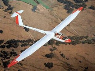
The J was succeeded by the A-21SJ, which first flew in May 1977 and was based on the production A-21S sailplane. The main difference between the A 21A and A 21 SJ is the positioning of the 198 lb st Microturbo TRS 18-046 turbojet engine. In remains in the fuselage behind the pilot, but now in the top position. Its air intake is by a removable NACA inlet located on the back of the fuselage. The ejection of the exhaust is by a nozzle opening on each side of the fuselage. The A-21SJ has a metal fuselage with fiberglass monocoque forward section surrounding aluminum load-carrying structure; all metal wings and tail with minor fiberglass fairing.
Caproni Vizzola Calif A-21SJ
Up to 242.5 lb of fuel is carried in fuselage and wing tanks, and there is a starter/generator and batteries for in-flight and ground starting. Apart from the engine the A-21 SJ is very similar to the A-21S, but has larger mainwheels and tailwheel. Two A-21SJs had been completed by May 1979 and five more were being built. One A-21SJ was being tested with a more powerful Microturbo TRS 18 jet of 242.5 lb st.
Prototype A21J Span: 20 36 m Length: 7 84 m Height: 1.919 m Wing area: 16,19 m² Wing loading: 39.8 kg / m² Maximum weight: 644 kg Max speed: 255 km / h Climb speed: 63 km / h
A 21J Engine: Sermel TRS 18, 220 lb. Seats: 2. Wing loading: 8.91 lbs/sq ft. Wing aspect ratio: 25. Gross: 1,543 lbs. Empty: 957 lbs. Useful: 586 lbs. Max airspeed: 162 kts. Rough air speed: 162 kts. Stall: 41 kts. Lift / drag: 43 at 63 kts. Sink: 1.97 fps at 49 kts. Fuel: 236 lbs. Length: 26 ft 3 in. Wing span: 65 ft 7.5 in
A-21JA Glide ratio: 1:43 at 58 kt / 1:42 at 60 kt. Never Exceed Smooth Air: 138 knots Max Rough Air: 91 kts Stall: 34 /38 knots Climb rate: 650 ft/min Ceiling: 30,000 ft Power Cruise: 115 kts
A-21S Span: 66ft 10.5 in Length: 25ft 4.5 in Height: 5ft 8.5 in Wing area: 174.3 sqft Aspect ratio: 25.65 Empty weight: 961 1b Max weight: 1,419 lb Max speed: 156 mph Max aero-tow speed: 87 mph Min sinking speed: 1.97 ft/sec at 53 mph Best glide ratio: 43:1 at 65 mph
A-21 SJ Span: 66 ft 10.25 in Length: 25 ft 4.5 in Height: 5 ft 3.5 in Wing area: 174.3 sqft Aspect ratio: 25.65 Empty weight: 1,164 lb Max weight: 1,781 lb Max level speed: 143 mph (power on) Max rate of climb: 787 ft/min (sea level, power on) Take-off run: 985 ft (power on)
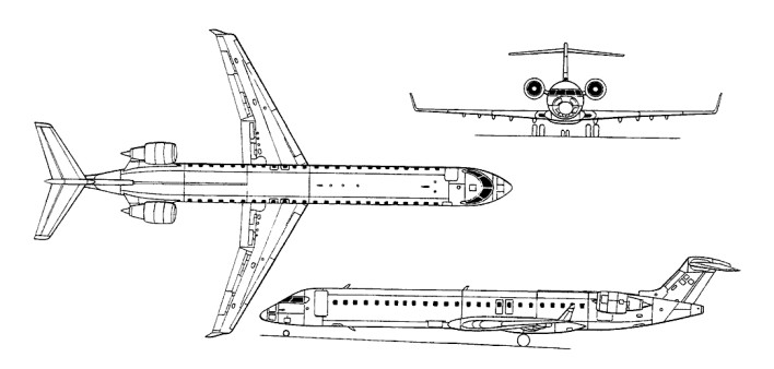
The CRJ 700 (originally known as the CRJ X) was a stretched 70 ¬seater, launched with a firm order for four aircraft from the French company Brit Air. Compared to the CRJ100/200 re¬gional jets from which it’s descended and with which it shares Collins ProLine 4 avionics, the CRJ700 features a fuselage stretch of 186 inches, new General Electric CF34 8C1 engines, a larger horizontal tail, leading edge slats and an APU in the tail cone instead of the equipment bay. Other changes in¬clude raising the passenger windows by 4.5 inches, lowering the floor an inch, and expanding the interior cabin by an inch to a total width of eight feet, five inches. The airplane’s commonality with the CRJ100s and 200s allow operators with both types an advantage in spares as well as pilot training. The GE engines are capable of 13,790 pounds of thrust with Automatic Power Reserve On May 27, 1999, the evening before its official rollout, Bombardier’s CRJ700, new 70 passenger Canadair Regional Jet airliner, made its first flight. The CRJ700 took off from Montreal, Canada’s Dorval Airport at 6:18 in the evening with test pilots, Craig Tylski and Chuck Ellis, on a test flight that lasted two hours and eight minutes. The public debut was at Farnborough International Air Show on 23 July 2000, and Transport Canada certification achieved 22 December 2000. The first customer delivery, to Brit Air of France, was in February 2001, followed by deliveries to Horizon Air and Lufthansa CityLine in May 2001.
The CRJ900 was originally CRJ700 Msn 10001, and the airframe was converted with two plugs of 90in (2.28m) and 62in (1.57m). The prototype retained the CRJ-700 wings, landing gear and engines, and was first flown on 21 February 2001, from Montreal-Mirabel, piloted by Chuck Ellis, Craig Tylski and Jeff Hyde. The public debut was at the Paris Air Show on 14 June 2001, and first production aircraft first flown on 20 October 2001. Transport Canada certification was achieved on 9 September 2002, followed by FAA approval 25 October 2002 and JAA certification 23 December 2002. The first customer delivery, to Mesa Air, was on 3 February 2003.
CRJ900
VERSIONS
CRJ-700 68-seat version in standard and extended range (ER) weight options. Engine: 2 x General Electric CF 34 8C1, 61313 N Length: 106.66 ft / 32.51 m Height: 24.836 ft / 7.57 m Wingspan: 76.247 ft / 23.24 m Wing area: 738.733 sq.ft. / 68.63 sq.m Max take off weight: 51255.2 lb / 23245.0 kg Weight empty: 30109.3 lb / 13655.0 kg Max. speed: 464 kt / 860 km/h Cruising speed: 442 kt / 818 km/h Service ceiling: 41011 ft / 12500 m Wing load: 69.5 lb/sq.ft / 339.0 kg/sq.m Range: 1701 nm / 3150 km Crew: 2 Payload: max. 8527kg
CRJ-701 70-seat version in standard and extended range (ER) weight options.
CRJ-900 Standard version. Length : 106.60 ft / 32.51 m Height: 24.836 ft / 7.57 m Wingspan: 76.247 ft / 23.24 m Wing area: 738.733 sq.ft. / 68.63 sq.m Max take off weight: 51255.2 lb / 23245.0 kg Weight empty: 30109.3 lb / 13655.0 kg Max. speed: 464 kt / 860 km/h Cruising speed: 442 kt / 818 km/h Service ceiling: 41011 ft / 12500 m Wing load: 69.5 lb/sq.ft / 339.0 kg/sq.m Range: 1701 nm / 3150 km Engines: 2 x General Electric CF 34 8C1, 61313 N Crew: 2 Payload: 70 pax (max. 8527kg)
900ER Extended-range version.
900ER European As 900ER but with maximum T-O weight limited to 36,995kg to minimise weight-related charges when operating in European airspace.
900LR Long-range version.
900LR European As 900LR hut with maximum T-O weight limited to 37,995kg.