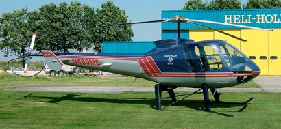
A number of models were developed and produced based on the body style of the 280. After preliminary market and design studies, Enstrom initiated the development of a larger, turbine-powered helicopter in 1988. Primarily developed from the four-seat Model 280L Hawk, the Eagle prototype, based on a converted 280FX airframe, flew for the first time in December 1988, powered by Allison 250-C20W turbine, followed by a definitive aircraft (N8631E) with a wider cabin on 7 October 1989. The 480 initial version has a five-seat (two plus three) configuration with staggered seating for forward visibility from all seats. Easily reconfigured to three seats for training or executive transport; or pilot’s seat only for transporting light cargo. Instrument panel centrally located above avionics console. Announced in February 1990, the Eagle is powered by an Allison 250 turboshaft. The second 480/TH-28 (production prototype) flew in December 1991. Initial FAA certification for the 480 was received on 7 June 1993; in December 1994, the approval was extended to FAR 27 standards.
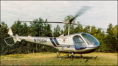
A three-seat version, designated TH-28, was proposed by Enstrom for the US Army’s New Training Helicopter (NTH) programme. Specially configured as a training light patrol helicopter: unique features include three crashworthy seats, crashworthy fuel system, and a large instrument panel which will accommodate dual instrumentation for either VFR or IFR training. Seating configuration allows training of two students simultaneously. The TH-28 was flown first in 1990. A production representative helicopter made its maiden flight on 21 December 1991. The TH-28 was granted FAA certification to C.A.R. Part 6 standards in September 1992. Turbine-powered certification of the TH28 came in September 1992 and the 480, to FAR Pt27 standards, in December 1994. Development of the more capable 480B variant powered by the Rolls Royce/ Allison 250-C20W turbine powerplant had begun in the spring of 1999, and FAA certification of the new model was obtained on 9 February 2001. In August 2003, the UK CAA also certified the Enstrom 480B turbine helicopter. The 480B basically equipped (2003) cost US$639,500, and features a high-inertia, three-blade, fully articulated main rotor system with upgraded main rotor gearbox, unboosted flight controls and high skid gear as standard equipment. The rotor speed is 372 rpm nominal; 385 rpm maximum permissible, and an anti-nodal vibrating cantilever beam to damp vibration at low speeds. The 480B cabin layout can be quickly reconfigured to seat one, three or five persons. A baggage compartment is in the tailboom. Optional equipment includes emergency pop-out floats, air conditioning and cargo hook rated for external loads up to 454kg. The 480B can also be fitted with police patrol equipment including special police radios, searchlight, siren/PA system, FLIR and data recording facility. The prototype, N480EN was exhibited at NBAA Convention, New Orleans, October 2000.
Production began in 1994 with initial deliveries to Europe. By June 2002, 43 480, 10 480B and four TH-28 had been registered. Final TH-28 produced in 1993 and delivered to China in 1993. Nine 480B delivered by mid-2003. Certified and operating in 14 countries: Australia, Belgium, Brazil, Canada, China, France, Germany, Japan, South Africa, Sweden, Switzerland, Thailand, UK and USA. In addition, 480 are also operating in Burkina Faso and Russian Federation. Customers include the Indonesian Police which ordered 18 480B in 2003.
TH-28 Engine: 1 x Allison 250-C20W. Instant pwr: 313 kW. Rotor dia: 9.8 m. MTOW: 1293 kg. Useful load: 533 kg. Max speed: 122 kts. Max cruise: 114 kts. Max range: 765 km. HIGE: 14,000 ft. HOGE: 12,000 ft. Service ceiling: 13,000 ft. Crew: 1. Seats: 3.
480 Engine: 1 x Allison 250-C20W, 212kW. Instant pwr: 313 kW. Rotor dia: 9.8 m. Length: 8.92m Height: 2.79m MTOW: 1293 kg. Useful load: 533 kg. Max speed: 122 kts. Max cruise: 114 kts. Max range: 765 km. HIGE: 14,000 ft. HOGE: 12,000 ft. Service ceiling: 13,000 ft. Crew: 1. Pax: 3/4. Seats: 5.
A conventional light helicopter with skid landing gear and tubular metal tail rotor protector; horizontal stabiliser with fins at tips. High inertia, three-blade fully articulated rotor head with blades attached by retention pin and drag link; control rods pass inside tubular rotor shaft to swashplate inside fuselage; no rotor brake: blade section MAC A 0013.5; blades do not fold; two-blade teetering tail rotor. Thirty-groove belt drive from horizontally mounted engine to transmission. Flying controls are conventional and manual. Trim system absorbs feedback from rotor and repositions stick datum as required by pilot.
The F-28A forward fuselage, consisting of the extensively glazed compartment for the pilot and two passengers seated side-by-side on a bench seat, is made of light alloy and glassfibre. The centre section of the fuselage, accommodating the engine, transmission and fuel tanks, as well as providing anchorage points for the steel-tube undercarriage skids, is more substantially built of steel tube. The rear fuselage, carrying small vertical tail surfaces and the two-blade teetering tail rotor of bonded light alloy construction, is a semi-monocoque structure basically conical in shape and built of aluminium.
Bonded light alloy blades. Fuselage has glass fibre and light alloy cabin section, steel tube centre-section frame, and stressed skin aluminium tailboom.
Skids carried on Enstrom oleo-pneumatic shock-absorbers. Air Cruiser inflatable floats available optionally. One 168kW Textron Lycoming HTO-360-F1AD flat-four engine with Rotomaster 3BT5EE10J2 turbocharger. Two fuel tanks, each of 79.5 litres. Total standard fuel capacity 159 litres, of which 151 litres are usable. Auxiliary tank, capacity 49 litres, can be installed in the baggage compartment. Oil capacity 9.5 litres. Pilot and two passengers, side by side on bench seat; centre place removable. Removable door on each side of cabin. Baggage space aft of engine compartment, with external door. Cabin heated and ventilated. Electrical power provided by 24V 70A engine-driven alternator; 12V 70A system optional. No hydraulic system.
Shoulder harnesses for three seats. Night lighting is optional for F28F. Night lighting includes instrument lighting with dimmer control, position light on each horizontal stabiliser tip, anti-collision light and nose-mounted landing light. Optional equipment for both F28F and 280FX includes fixed float kit, wet or dry agricultural spray kit and cargo hook for utility missions. Wide instrument panel available for IFR training.
The two-seat prototype of the F-28 was flown first on 12 November 1960 with a two-bladed main rotor and an un-skinned tubular rear fuselage, followed by the first of two three-seat production prototypes on 26 May 1962. Initial FAA certification was achieved for the F-28 model in April 1965 and deliveries began in 1965. The production version appeared in the autumn of 1963. Powered by a 134kW Avco Lycoming O-360-A1A engine, it had a three-bladed main rotor and a light alloy and glassfibre cabin section with an all-metal semi-monocoque tail boom. Enstrom sold only nine F-28s before being purchased by the Purex Corporation in early 1968. An improved version of the F 28, powered by a 205 hp Lycoming H10 360 C1B and called the F 28A, was certificated in May 1968. Production of the three seat F-28A started in 1967 but only 35 were sold before Purex suspended all operations in February 1970.
The F 28A uses a normally aspirated 205 hp engine. The main rotor blades are of bonded construction and have no time limit, mainly be¬cause the F 28 rotor system originally was designed to be rigid in plane, so the blades are heavier and experience lower working stress levels than if the F 28 had been de¬signed initially to employ its present fully articulated three blade system.
The F 28A offers a cruise speed of 87 knots. Enstrom offers an option, called a throttle correlator, that is designed to facilitate throttle/collective coordination. It employs a cam like arrangement that partially couples the collective and throttle, but even the folks at Enstrom did not recommend it with much enthusiasm.
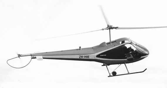
F-28A ZK-HIE
The rugged rotor system of the Enstrom gives the F 28A a heavier cyclic, or attitude, control feel than is found on other light helicopters, such as the Hughes 300. By fixed wing standards, however, the control pressures are low. The somewhat heavier cyclic control force characteristics combine with a fairly large, six inch offset in the flapping hinge to give the F 28A a nice harmony between stability and control over an allowable CG range of six inches. When the helicopter is disturbed either by a gust or a sudden cyclic control input, the F 28A experiences an initial divergence in roll or pitch but not the wild type of response that is frequently imagined to exist with helicopters. An electric pitch and roll trim, which is operated by a thumb switch on the cyclic stick, allows a pilot to remove residual control forces and establish a hands ¬off trim condition in cruising flight.
Because of its heavier rotor blades (at 51 pounds each, they are nearly twice the weight of those on the Hughes 300C), the F 28A does not gain lost rotor rpm as quickly as does a helicopter with a lighter rotor system. The higher inertia of the Enstrom rotors, however, does enable the F 28A to hold its rpm longer, at times when the pilot may need to use the rotational energy stored in the whirling rotor system.
In 1976 the improved F-28C was produced. The basic F28A and 280 were replaced by turbocharged F28C and 280C, certified by FAA 8 December 1975.A turbocharged conversion by Enstrom maintains full rated power up to 12,000 ft. Fixed waste gate Rajay 301-E-10-2 turbocharging on the Enstrom’s 153kW / 205 hp Lycoming HIO 360-E1AD engine enables the F 28C and the 280C to lift their 2,400 pound gross weights at density altitudes up to 13,000 feet. In addition to the turbocharging, Enstrom shifted the tail rotor from the right to the left side of the tail boom, thus placing the anti torque device where it reacts more favorably with the main rotor’s downwash and, therefore, is more effective. A tail rotor blade with a wider chord has been tested and is being retrofitted to all C models of the F 28 and the Shark 280. The FAA has approved the modification.
The F-28C-2 introduced a one-piece windscreen and a pedestal central instrument console for improved forward and downward vision. The 500th helicopter was delivered during June 1977. Production ceased in Novembr 1981, succeeded by the F28F.
Although the Enstrom helicopters are intended mainly for light passenger operations, the F-28C and Model 280C can be used in the agricultural role with two side-mounted chemical hoppers and their associated spraybooms. Liquid chemical capacity is 340 litres, and powder chemical capacity 0.5cu.m.
F-28F Falcon/280F was FAA certificated in January 1981, powered by the turbocharged 168kW Avco Lycoming HIO-360-F1AD engine. The basic F28F Falcon model was certified to FAR Pt 6 on 31 December 1980. The two major changes were incorporated into the F28F and 280F/280FX over the earlier F28C/280C series were an increase in power from 153kW to 168kW / 225shp and the addition of a throttle correlator to reduce pilot workload. Changes to the F28F and 280FX are the redesigned main gearbox with a heavy wall main rotor shaft (standard equipment on all new aircraft and retrofittable to all existing F models); optional lightweight exhaust silencer, which reduces noise in the hover by 40% and gives a 30% reduction when flying at 152m (can also be retrofitted to F28F, 280F and 280FX); and a lightweight starter motor.
A dedicated police version of Model 280F, the F-28F-P Sentinel, was developed for the Pasadena Police Department, and fitted with special equipment including a searchlight. First delivery was in October 1986. The development of a turbine-powered model was initiated in 1988, culminating in certification of the TH28 in September 1992.
The T-28 experimental version featured a 240 shp AiResearch TSE 36-1 turboshaft engine, increased fuel, larger diameter tail rotor, and a new transmission system.
Customers total 735 of earlier versions (14 F28, 315 F28A, 121 F28C, 56 F28C-2, 21 280, 206 280C and two 280L). Last of 135 F28F delivered 1999 to Fresno Police Department, California, but further nine produced in 2002 and 2003. Total of 98 280FX built up to mid-2003, increasing Enstrom piston-engined helicopter production to 966; further two 280 registered in early 2003, Peruvian Army has 10 F28F for flight training; Colombian Air Force operates 12 F28F for primary and instrument training, Numerous US police departments operate F28F-P for patrol and surveillance missions.
The basic 2004 price was US$320,000 for F28F Falcon and 280FX Shark.
F-28A Engine: Lycoming HIO-360-C1A, 205 hp. Main rotor dia: 32 ft / 9.75 m Disc loading: 2.67 lb/sq.ft. Pwr loading: 10.48 lb/hp. Length: 29 ft 6 in / 8.99 m Cabin max width: 5 ft 1 in / 1.55 m Empty wt: 1450 lb / 657 kg Max wt: 2150 lb / 975 kg Equipped useful load: 642 lb. Payload max fuel: 402 lb. Max sling load: 500 lb. Range max fuel/ cruise: 204 nm/2.1 hr. Range max fuel / range: 240 nm/ 237 mi / 381 km / 3.3 hr. Luggage cap: 7 cu.ft or 60 lbs. Vne: 98 kts. Cruise: 87 kt / 100 mph / 161 kph Max cruise: 93 kt. Max range cruise: 74 kt. Service ceiling: 12,000 ft / 3660 m Hover IGE: 5600 ft. ROC: 950 fpm / 290 m/min Best climb/glide speed: 58 kts. Fuel cap: 240 lb / 30 USG. Endurance: 2.5 hr. Baggage hold: 8 cu ft / 0.33 cu m Seats: 3.
F-28B Engine: Lycoming TIO-360, 275 hp
Enstrom F-28C Engine: 1 x Avco Lycoming HIO-360-E1BD, 153kW Main rotor diameter: 9.75m Length: 8.94m Height: 2.79m Max take-off weight: 1066kg Empty weight: 680kg Max speed: 180km/h Cruising speed: 172km/h Ceiling: 3660m Range: 435km Crew: 1 Passengers: 1
F-28C-2 Falcon Engine: Lycoming HIO-360-E1AD, 205 hp. TBO: 1000 hrs. Main rotor: 32 ft. Seats: 3. Length: 28.2 ft. Height: 9.2 ft. Max ramp weight: 2350 lbs. Max takeoff weight: 2350 lbs. Max wt (100mph restriction): 2500 lbs. Max wt (90mph restriction): 2600 lbs. Standard empty weight: 1562 lbs. Max useful load: 788 lbs. Max landing weight: 2350 lbs. Max sling load: 800 lbs. Disc loading: 2.9 lbs/sq.ft. Power loading: 11.5 lbs/hp. Max usable fuel: 240 lbs. Max rate of climb: 1200 fpm. Service ceiling: 12,000 ft. Hover in ground effect: 9700 ft. Hover out of ground effect: 6000 ft. Max speed: 97 kts. Normal cruise @ 3000 ft: 90 kts. Fuel flow @ normal cruise: 78 pph. Endurance @ normal cruise: 2.9 hr. Max range cruise: 74 kt Range max fuel / range: 196 nm/ 2.7 hr Range max fuel/ cruise: 178 nm/1.9 hr
F-28F Engine: Lycoming HIO-360-F1AD, 225 hp. TBO: 1000 hrs. Main rotor: 32 ft. Seats: 3. Length: 28.2 ft. Height: 9.2 ft. Max ramp weight: 2600 lbs. Max takeoff weight: 2600 lbs. Standard empty weight: 1562 lbs. Max useful load: 1038 lbs. Max landing weight: 2600 lbs. Max sling load: 1000 lbs. Disc loading: 3.2 lbs/sq.ft. Power loading: 11.6 lbs/hp. Max usable fuel: 240 lbs. Max rate of climb: 1450 fpm. Service ceiling: 18,000 ft. Hover in ground effect: 12,400 ft. Hover out of ground effect: 7500 ft. Max speed: 97 kts. Normal cruise @ 3000 ft: 94 kts. Fuel flow @ normal cruise: 96 pph. Endurance @ normal cruise: 2.4 hr.
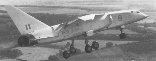
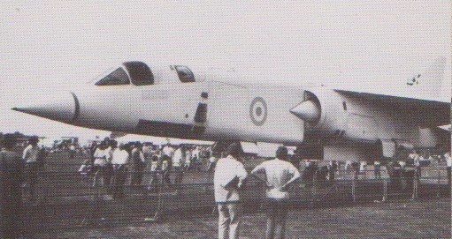
English Electric TSR-2 Mach 2 tactical strike and reconnaissance aeroplane, evolved from the P.17A concept. The TSR-2 remains the classic example of technical and operational promise ultimately stultified by economic worries and finally denied by political prejudice. It resulted from a May 1957 Royal Air Force requirement for a tactical strike and reconnaissance aeroplane to replace the English Electric Canberra, which would be able to operate at very low levels at supersonic speed, deliver heavy weapon loads over long ranges with very high accuracy, and operate from short runways through the provision of STOL capability.
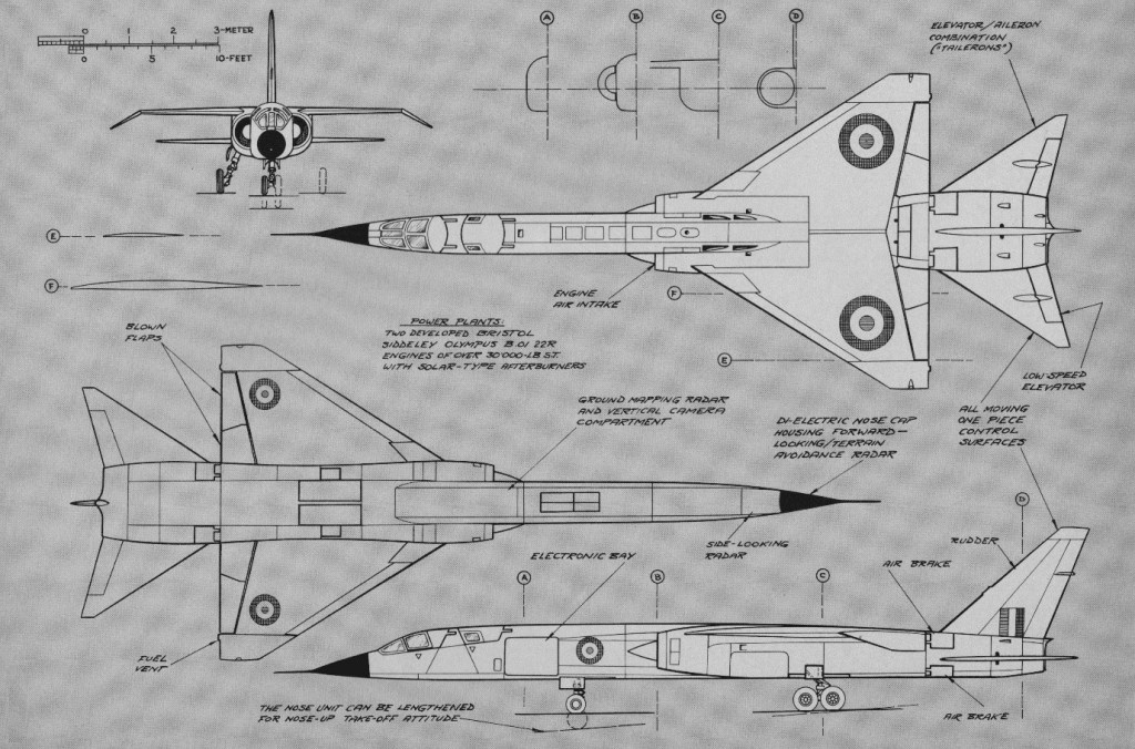
The two most promising contenders were those from Vickers and from English Electric in collaboration with Shorts. The RAF opted for a combination of features from the two designs, and the government virtually forced English Electric and Vickers to merge as the British Aircraft Corporation, which also incorporated Bristol Aircraft. The development of the new aeroplane pushed forward the technologies of the time quite considerably in a number of fields, and inevitably involved a number of companies other than BAC (overall responsibility and airframe) and Bristol Siddeley (powerplant). Other major contributors were Elliott Automation for the integrated automatic flight control and inertial navigation systems, Ferranti for the terrain-following radar and nav/attack system, EMI for the side-looking radar used for reconnaissance and additional navigation input in long-range flights, and Marconi for the avionics.
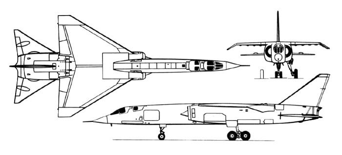
The design was frozen in 1962 and construction of the prototypes began. There were many problems to be overcome, but the promise was a warplane more advanced than any in service or under development anywhere in the world at that time. Pitch and roll control was entrusted to the all-moving tailplane working collectively or differentially, and this allowed the entire trailing edge of the wings to be used for the blown flaps that contributed signally to the TSR-2’s STOL capability. The nav/attack system was extremely advanced, and in combination with the automatic flight control system permitted supersonic terrain-following flight at heights down to 200 ft (61 m).
The Bristol Siddeley Olympus development became the pacing factor for the project, falling behind schedule and continually plagued with problems. Even when the TSR2 eventually got airborne for the first time, it did so with strictly non airworthy engines, which had to be operated at reduced power.
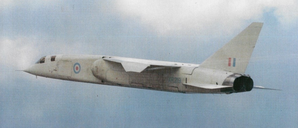
Eventually the first prototype, XR219, became airborne for its maiden flight on 27th September 1964, six and a half years after the original requirement was raised. In the event, it was to be the only prototype to fly. The second one, XR220, fell off the back of a lorry on delivery to Boscombe Down, and it says much for the strength of the airframe that the subsequent rigging checks revealed nothing out of alignment. It was just ready for flight when cancellation came. It carried one of the few noticeable external differences, this being the fitting of camera fairings to each side of the engine intakes, to photograph underwing stores separation tests. The third machine, XR221, was intended to be the full electronics test aircraft, and was under¬going trials at Weybridge prior to flight. The fourth, XR222, was also virtually complete.
All the flying was done by XR219, lasting barely six months, and totalling only 24 flights.
In the first Budget Speech by the newly elected Labour Government in 1965, the cancellation of the whole programme was announced. Not only was it to be cancelled, but to ensure that the project could never be resurrected, all jigs, production drawings and completed components were to be totally destroyed. A proposal was made that XR219 should be kept flying for pure research purposes, but this was also rejected, and the contract was officially terminated on 6th July 1965, in favour of the General Dynamics F-111. The F-111 programme then suffered a number of severe problems and escalating costs, and the British order was cancelled.
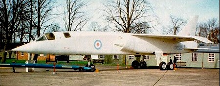
At cancellation, in addition to the three com¬pleted aircraft, there were 17 others on the production line, as well as major com¬ponents for several others, with long lead items for a total of a further 50 aircraft. The first prototype was sent to Shoeburyness to act as a gunnery target to assess damage to modern air-frames. XR220 was allocated to the Royal Air Force Museum and XR222, after a spell at Cranfield, to Duxford as a part of the Imperial War Museum’s collection.
Engines: two Bristol Siddeley Olympus Mk 320 turbojets, 30,610 lb (13,885-kg) afterburning thrust Wingspan 37 ft (11.28 m) Length 89 ft (27.13 m) Height 24 ft (7.32 m) Wing area 700 sq.ft (65,03 sq.m) Maximum speed at high altitude 1360 mph (2185 km/h) or Mach 2.05 Maximum speed at sea level 840 mph (1352 km/h) or Mach 1.27. Empty weight 44,850 lb (20,344 kg) Maximum take-off weight: 95,500 lb (34,500 kg). Ceiling: 16500 m / 54150 ft Range w/max.fuel: 6840 km / 4250 miles Range w/max.payload: 1280-1850 km / 795 – 1150 miles Operational radius 1,152 miles (1853 km) with 2000lb (907-kg) internal warload Crew: 2 Armament: internal 6000-lb (2724-kg, 4 x underwing hardpoints max 6000 lb (2722 kg)
As chief engineer of English Electric’s Aircraft Division it was W.E.W.(Teddy) Petter’s responsibility to keep looking at new projects. Towards the end of 1946 he spent some time sketching possible configurations for a supersonic aeroplane. It was characterised by sharply swept wings and tailplane and a long slab sided body with two engines one above the other. He had discussions with officials at the Ministry of Supply early in 1947, and was rewarded in May of that year by a study contract for an aircraft to meet a supersonic specification, ER.103 (ER= experimental research). The officials suggested Mach 1.5, equivalent at 36,000ft to about 860 kt. The Air Staff agreed to write a specification for an aeroplane “to investigate the practicality of supersonic speed for military aircraft”, designed to have fighter like handling characteristics, to be built to fighter strength factors (7g) and to carry guns and a sighting system.
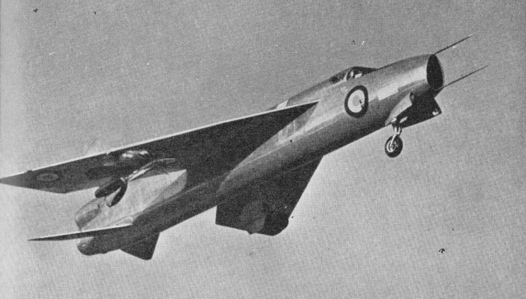
The specification was F.23/49. It was not put out to general tender; instead English Electric were awarded a contract for two flight prototypes and a static test airframe. They called the aircraft the P.1 (project 1). It followed Petter’s long earlier refinement of the classic configuration he had conceived, with the single notable change that he put the tailplane very low on the rear fuselage instead of on top of the fin. He chose to use a pair of simple Armstrong Siddeley Sapphire turbojets, with plain fixed nozzles and no reheat, and fed by a plain inlet in the nose. This was in keeping with his “simple, off the shelf” philosophy. To minimise frontal area he staggered the engines, bringing the lower one well forward with a long jet pipe. After a lot of study he adhered to his original plan to have a mid wing, with the engine air ducts passing above and below it. The form of the wing was crucial, and unique, notable features being the fact that the 60O sweep halved the apparent ratio of thickness to chord and allowed it to have a generous radius on the leading edge, and the ailerons joined the leading and trailing edges in a novel way. Petter left the body free of fuel and marked out part of the main torsion box of the wing to serve as an integral tank. He devoted a large bay to the rear of the torsion box to house the main gears in an unusual installation with doors hinged on the inboard side of the wheel well, even though the legs retracted outwards. The legs had to be long, because it was clear that the P.1 would take off and land at a marked nose up angle. Owing to the thin wing the wheels had to be of large diameter and have tyres inflated to high pressure (no less than 2801b/sq in). To minimise drag the canopy was made flush with the top of the fuselage, though a flat windscreen was provided for the gunsight. The nosewheel folded forwards and turned to lie flat under the inlet duct. All controls were fully powered, the horizontal tail being of the new “slab” type, and there were sharply swept split flaps. Petter was careful not only to stress the P.1 for 7g but also to make weight provision for a military payload. So advanced was the design – and so complex the aerodynamic problems which this design posed – that Britain’s first transonic wind tunnel was built to facilitate testing. Short Brothers at Belfast were instructed by the Ministry of Supply (MoS) to build a research aircraft able to investigate aspects of Petter’s design which the MoS considered more revolutionary than functional. Thus Short’s S.B.5 had a wing which could investigate sweepback at 50 degrees, 60degrees and 69degrees, landing gear which could be adjusted to cater for the CG changes in these different configurations and, at a later stage, a low-set tailplane. When both wind tunnel testing and S.B.5 confirmed that Petter’s design had been right from the outset, the MoS let English Electric get on with construction of two prototypes and a static test airframe.
Pilot – Wg.Cdr. R.P.Beaumont
English Electric P1A, WG760, was the first of two prototypes and had its maiden flight on 4 August 1954, piloted by Roland Beamont. On its third flight the aircraft became the first British aircraft to exceed Mach 1 in level flight. On his third flight the Mach needle refused to move beyond 0.98, but subsequent analysis suggested the P.1 had gone supersonic. Later this machine, WG760, and its partner, WG763 (which had guns, and first flew on July 18, 1955), explored the flight envelope to mach 1.53, demonstrated superb handling qualities and were later given a bigger fin to ensure ample stability margins at high Mach numbers, and a neat faired in belly tank to increase the fuel capacity above the original limit of a mere 5,000lb. The first aircraft flew with Sapphires with crude reheat and fixed area nozzles sized to the reheat condition.
P.1B
The second flew with a revised wing with a kinked leading edge and broad tips with inset ailerons which gave better low speed lift and longer range, as well as opening out the high altitude buffet boundary.
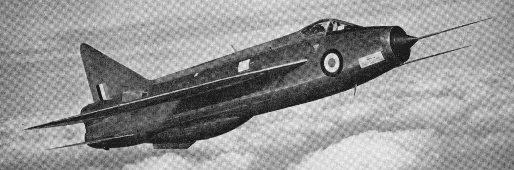
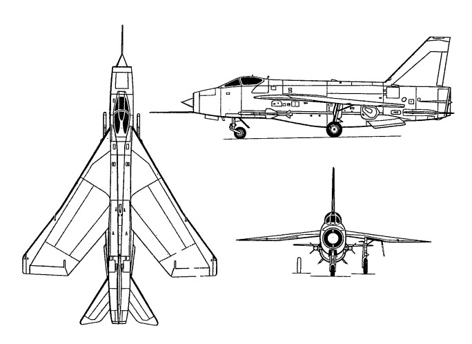
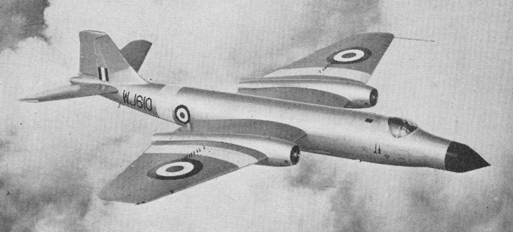
In 1953 a standard of build was agreed for an operational fighter designated P.1B. It was to carry the Ferranti AI 23 radar in the pressurized conical centrebody of a redesigned inclined shock intake with a centrally mounted shock cone, and have a removable armament pack carrying two Blue Jay (Firestreak Mk 1) guided weapons on external pylons, plus their associated electronics and interface systems, or as an optional alternative, two 30mm Aden guns and ammunition. A third alternative was two retractable boxes, each housing 24 FFARs (foldingfin aircraft rockets). After a lot of argument it was also agreed to fit a 30mm Aden gun on each side of the cockpit in a permanent installation. The engines were changed to Rolls-Royce Avon 201s, with four stage reheat, the flaps were made of the plain type (and later used as integral tanks), the fuselage was redesigned with a raised clear vision canopy and many other changes (such as new air¬brakes and dozens of access panels to the profusion of added equipment items), the nose gear was redesigned to fold into the “6 o’clock” inlet strut, and there were countless less obvious changes such as an air bleed turbo¬alternator. The kinked/cambered wing was not incorporated, neither was a refuelling probe. The first of the three hand-built P.1B prototypes first flew on 4 April 1957 with the more powerful engines mounted one above the other in the rear fuselage, with the lower engine well forward of the upper. The production F.1 Lightning began to enter service with the Central Fighter Establishment at RAF Coltishall in December 1959, and after protracted development the Lightning finally entered service in May 1960 with No 74 Squadron. The third aircraft built, a P.1B, became the first British aircraft to exceed SQ.M.0 on 25 November 1958. The jet is capable of cold start to airborne in 1.5 minutes, a climb to 40,000 ft in 2.5 minutes from brakes off and a zoom climb to over 70,000 ft. Twenty development machines had been ordered, the first of these, XG307, flying on April 3, 1958. These led, fairly smoothly into the production fighter, which in October 1958 was named Lightning F.1, and CA Release was obtained late in 1959, No 74 “Tiger” Sqn being equipped at Coltishall the following July and August. The Lightning PE1B XG337 was the last of 20 pre-production Lightnings used for armament, powerplant and radar testing at Farnborough.
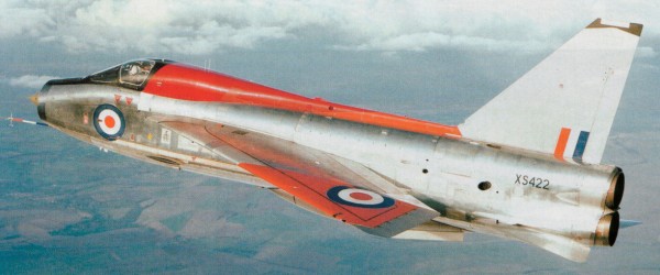
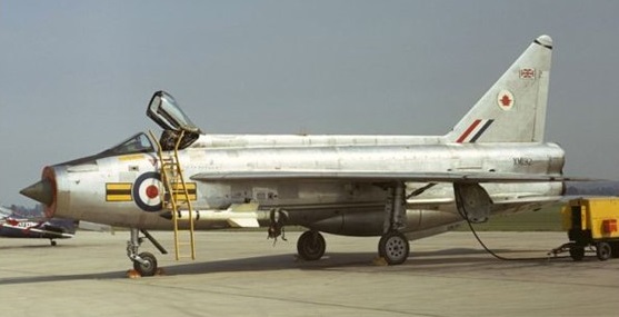
English Electric Lightning F1A, RNAS Yeovilton (8 September 1973)
Gradually the Air Staff and ministry officials grudgingly permitted small improvements to be made. The Mk 1A introduced a crude refuelling probe fixed under the left wing (nobody would pay for a neat folding one); the Mk 2 brought in improved Avon 210 engines and numerous systems advances. The F.3 (which entered RAF service in January 1964) was the major production version having an improved radar and collision course Red Top missiles, as well as more powerful Avon 301 engines and other changes including a bigger square topped fin.
Lightning T.4
Thirty RAF Lightning F.2s were to be modified to F.2a from 1967, incorporating the larger ventral fuel tank of the Mk.6 or, alternately, the mixed fuel tank/twin-Aden gunpack ventral bulge.
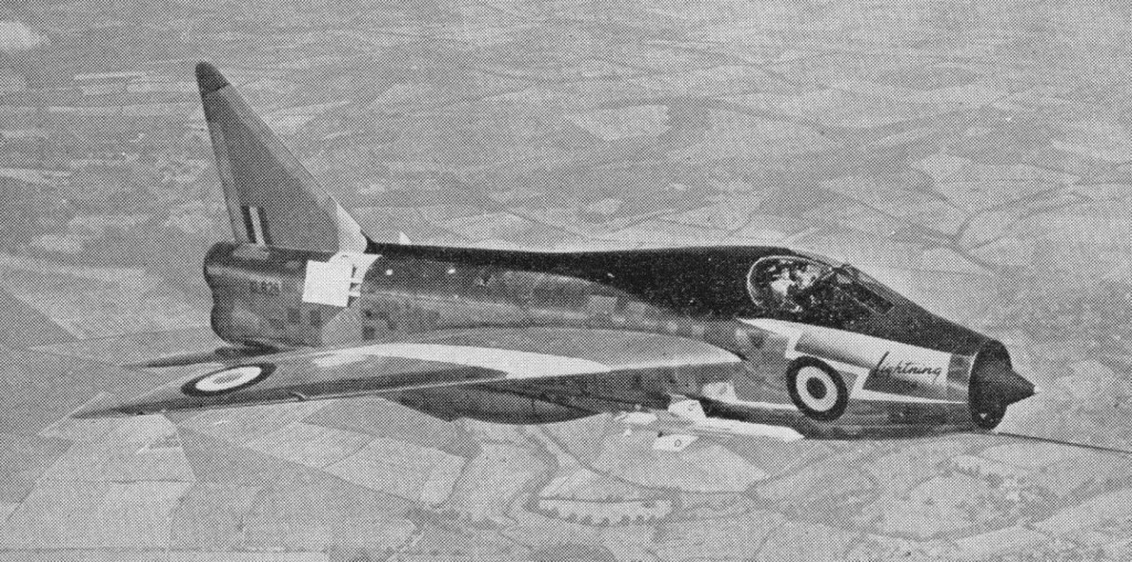
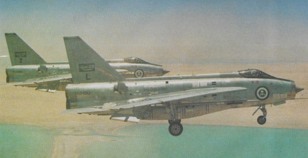
The T.4 was a dual control side by side Mk 1A; the T.5 was a dual control Mk 3; and the Mk 6 was the result of common ¬sense finally creeping into the minds of the Air Staff. With the Mk 6 BAC, as the company had become in 1960, were allowed to fit a proper fuel system, with roughly double the capacity of the early versions. One visible manifestation of this was the area ruled ventral bulge, housing 600gal, which could also carry twin 30mm Aden guns or other stores (the original nose guns had been left off and then later put back again) and overwing pylons for twin 260gal ferry tanks or force ejected retarded bombs. The Mk 6 also, at last, got the improved wing. The F.6 entered service during August 1966 and remained operational until 30 June 1988. While Mk 3s were expensively modified to Mk 6 standard, in 1964 BAC were able to offer an export version (with racks for a 4,0001b load under wing), and sold F.53 and T.55 Lightnings to Saudi Arabia (which led to a further BAC assistance deal in 1972 73). Kuwait bought a smaller number.
285 were built for the RAF or development service.
A total of 338 Lightnings were built by English Electric and the British Aircraft Corporation.
Lightning F.1 Engine: 2 x Rolls Royce Avon 210, 64206 N / 6545 kp / 17,250 lb Length: 55.249 ft / 16.84 m Height: 19.587 ft / 5.97 m Wingspan: 34.81 ft / 10.61 m Max take off weight: 41707.6 lb / 18915.0 kg Max. speed: 1303 kts / 2414 km/h Service ceiling: 62073 ft / 18920 m Range: 778 nm / 1440 km Crew: 1 Armament: 2 MK 2 A/A FK
F.1A Engines: 2 x Rolls/Royce Avon, 14,430 lb. Wing span: 34 ft 10 in (10.61 m). Wing area: 380.1 sq.ft Length: 55 ft 3 in (16.84 m). Height: 19 ft 7 in (5.97 m). Wheel track: 12 ft 9.25 in Armament: 2 x 30mm Aden cannon
F.3 Seats: 1. Wing span: 34 ft 9 in.
F.6 Engines: 2 x 16,360 lb. (7,420 kg.) thrust Rolls Royce Avon 301 turbojet. Length 55.25 ft. (16.84 m.) Wing span 34.8 ft (10.61m). Seats: 1. Armament: 2 x 30 mm. cannon and two Redtop missiles, 4 hardpoints Max speed: Mach 2.0.
T.5 Seats: 2.
Lightning Mk53 Length (including pitot probe): 55ft 3in / 16.84m. Height: 19ft 7in / 5.97m. Wing Span: 34ft 10in / 10.61m. Wing area: 460 sq ft. / 42.7sq.m. Track: 12ft 9.5in / 3.89m. Wheelbase: 18ft 1.5in / 5.52m. Sweepback (leading edge): 60 degs. Empty wt (with gun pack and missiles): 29,600 lb / 13,426kg. Maximum Take off wt (Fully armed Mk53): 41,700 lb / 18,914kg. Gross wt: approx. 45,000 lb / 20,412kg. TO run (at 38,500 lb / 17,464 kg: 3300 ft / 1006m. Time from brakes release to Mach 0.9 at 40,000ft: 150sec. Time to accelerate from Mach 1 to over Mach 2: 210sec. Landing (with parachute) at 29,000 lb (13,154kg): 3,600ft / 1,097m. Landing run (at 38,000 lb / 17,237 kg: 4500 ft / 1371m. Max speed: Over Mach 2 (over 1,500 mph / 2,414km/hr). External fuel cap: 520 Imp.Gal / 2364 lt.
Engines: 2 x RR “Avon 302C”, 58.8kN Max take-off weight: 19000 kg / 41888 lb Wingspan: 10.6 m / 34 ft 9 in Length: 16.8 m / 55 ft 1 in Height: 6.4 m / 20 ft 12 in Wing area: 35.3 sq.m / 379.97 sq ft Max. speed: M.3 Ceiling: 18300 m / 60050 ft Crew: 1 Armament: 2-4 x 30mm machine-guns, 2 guided or 48 unguided missiles
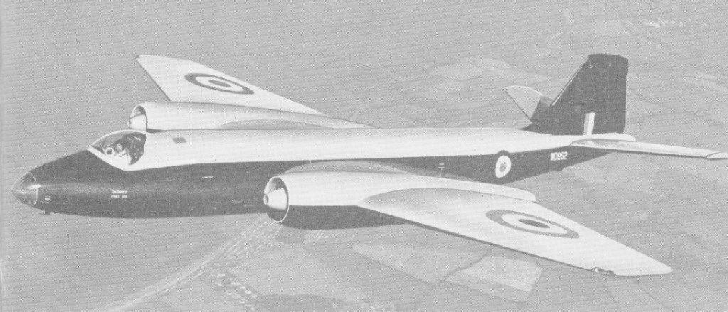
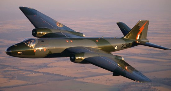
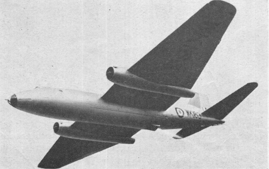
Early developments of the turbojet engine, with then very limited power output, restricted somewhat the size and type of aircraft able to take advantage of this new power plant. Thus, it was not until Air Ministry Specification B.3/45 was issued that the English Electric Company was able to design and build Britain’s first turbojet-powered bomber -the first such aircraft to serve with the RAF. W.E.W. ‘Teddy’ Petter, former chief designer at Westland, was hired by English Electric in 1945 to give this company the ability to design its own aircraft. The resulting English Electric Canberra (the first prototype, VN799) (designed to the high altitude bomber specification B3/45) first flew on 13 May 1949 piloted by Roland Beaumont, and astonished everyone by its amazing agility, though its bombload was 2722 kg (6,000 lb).
A B.2 was ready for delivery from English Electric in November 1951. It was issued to Bristol Aero Engines at Filton for development work on the Olympus destined to power the Vulcan and much later, Concorde. Delivered to Filton in December 1951, WD952’s engine bays underwent a radical re engineering to accommodate the Olympus the engine would project much further forward than the Avon that the Canberra was designed around.
Fitted with a pair of Olympus B.01.1/2BS of 8,000 lb st (35.5kN), WD952 first flew in this guise on August 5, 1952 just 25 days before the prototype Vulcan undertook its maiden flight. As well as undertaking development flying for the engine, it was soon clear that the Canberra Olympus combination offered significant gains in altitude and Bristol’s chief test pilot, W/C Walter Gibb achieved a Class C world record of 63,668ft (19,406m) on May 4, 1953.
Olympus testbed
As Olympus development continued, WD952 was re engined with the Series 101 of 11,000 lb st (48.9kN) and then in 1955 with the B.01.11 (the Series 102) of 13,000 lb st (57.8kN). With the 102s in place, W/C Webb achieved another world record for altitude on August 29, 1955, this time with 65,876ft (20,079m). The aircraft performed at that year’s SBAC display at Farnborough the nose placarded with details of its record flights. On March 12, 1956, WD952 came to grief in a crash near Filton.
The Canberra has unswept wings and tail surfaces, a variable incidence tailplane, split trailing edge flaps and finger type airbrakes in top and bottom wing surfaces. The tricycle undercarriage has twin nose-wheels and single wheels on each main unit. The nose wheel retracts rearward and main wheels into the centre section.
Four prototypes of the English Electric A1, later designated as B.1s, were all used for development flying. The initial order was for 130, in three variants, and the type was put in production in 1949 by the English Electric Co at Preston, Short Brothers and Harland, Avro, and Handley Page.
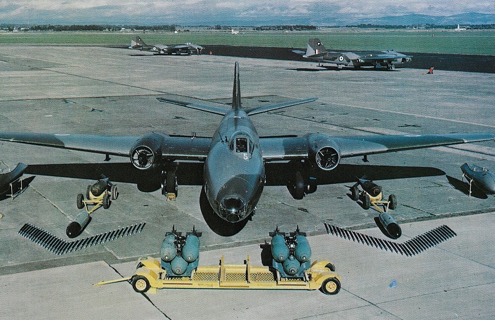
The original intention had been to produce a two-crew aircraft which would rely upon radar for the accurate delivery of its bomb load. But although the four prototypes were built to this configuration, the first production Canberra B.2 carried a crew of three and were configured for visual bombing. Of mid-wing monoplane configuration, all-metal, semi-monocoque construction with a cantilevered wing and a wooden vertical stabiliser, these aircraft were powered by two 28.91kN Rolls-Royce Avon 101 engines and could carry internally 2,722kg of conventional or nuclear weapons. Canberras entered RAF service with No 101 Squadron at RAF Binbrook in May 1951. These aircraft were unarmed, relying (as had the war-time de Havilland Mosquito) on speed.
Canberra TT.18
The major production variant was the B.2 bomber the first prototype flying on April 21, 1950. B.2s were built by English Electric, Avro, and Handley Page. Conversions of the B.2 were as follows: T.4, B.8, U.10 (D.10), T.11, U.14 (D.14), T.17, TT.18 plus some to B(TT).2 target tug status and one to B.2E for special fit trials. The type did not officially adopt the name Canberra until January 1951.
The photo reconnaissance version of the B.2, including slightly lengthened fuselage was designated PR.3. Prototype first flown March 19 1951. The B.2 three seat tactical bomber which entered service with the RAF in January 1951 had 6500 lb Avon 101 engines.
Dual control trainer version of the B.2, readily identifiable by its ‘solid’ nose was the T.4. Prototype first flown on June 6, 1952, entering service in 1954.
A ‘Pathfinder’ or target marker version of the B.2 was the B.5, the prototype of which was flown for the first time on July 6, 1951. Only one, VX165, was produced this aircraft was converted to B(1).8 status and later used for PR.9 development work.
An improved B.2 with more powerful Avons and increased range was the B.6. The first production B.6 flew on January 26, 1954, introducing more powerful engines and increased fue capacity. B.6s were built by English Electric and Shorts. An interim bomber interdictor variant, with wing pylons for bombs and a ventral gun pack, the B(1).6 was also produced. The first production B(1).6, WT307, was used for a variety of trials, it finally served with RAF Germany before retirement in 1969. Some B.6 airframes were converted to B.15 and B.16 status carrying two 1000 lb bombs or packs of 37 unguided rockets under their wings in addition to a full bombload, and others were converted to take BLUE SHADOW equipment as B.6(BS), and others for radar research. A conversion of the B.6 with additional underwing hardpoints for weapons was designated B.15, and a generally similar B.16 with more radar equipment.
Canberra B.6
The B.2 and B.6 were in service with the air forces of Rhodesia, Venezuela and Ecuador.
Eighteen B.2s were converted by Shorts (company designation SC.4) to U.10 (later D.10) pilotless drone status for use on the Australian ranges at Woomera. The first aircraft was first flown in this form on June 11, 1957. One U.10 was later upgraded to U.14 status.
The PR.3 carried seven cameras for high altitude reconnaissance.
Shorts SC-4
The PR.7 was a photo reconnaissance version of the B.6; the prototype first flying on August 16, 1953.
Venezuelan Canberra B.2
A Napier Scorpion rocket assisted Canberra set a World Altitude Record of 70,309 ft in 1957.
Napier Scorpion rocket power altitude record setter
Seven PR.7s were converted to TT.22 status and one to interim high-altitude PR.9 guise. Deliveries of T.22 Canberras to the Royal Navy began in November 1973. They were used for radar training and are basically rebuilt PR.7s.
Canberra B(I).8
The Canberra B(l)Mk 8 of 1954 introduced a new nose with the nav/bomb aimer in front and the pilot under a fighter canopy offset to the left; previous marks had mainly been three seaters with two crew in ejection seats behind the pilot. The radar equipped Canberra B.Mk 1 was not put into production, so the first variant was the Canberra B Mk 2 with a visual bomb aiming position in the nose for a third crew member, who had to leave his ejection seat before the high level bombing run. Normal bombload was tandem triplets of 454¬kg (1,000 lb) weapons. The Canberra B.Mk 6 introduced more powerful engines as well as underwing pylons for two further 454 kg (1000 lb) bombs, and like some other versions added fuel in the leading edge of the outer wings. All bomber versions were equipped with a visual aiming station in the nose, though the offset canopy Canberra B(I).Mk 8 and its many derived export versions normally operated at low level and bombs were sometimes released by the pilot in close dive attacks. These tactical models could also be fitted with a removable pack of four 20 mm cannon with well over 2,000 rounds of ammunition. The Canberra 8 is distinguished from previous variants mainly by the revised cockpit, which is moved back and is offset to the port side so that the pilot now sits in a long blister canopy. It appears that the second crew member carried for this role is now housed forward of the pilot instead of behind and has no ejection seat. The Canberra 8 has Rolls Royce Avon RA.7 engines of increased power. The B Mk. 6 and PR.7 have the same span of 63 ft. 11 in. as the B.2 and PR.3, but their length has been increased to 66 ft. 9 in.
With the arrival of the B.(1).8, the RAF at last had a dedicated interdictor, capable of night strikes. The prototype was the reworked B.5 one off, VXL85 which first flew in the new form On July 23, 1954. Production was carried out by both English Electric and Shorts. Most obvious change was the fighter like canopy, offset to port, allowing the navigator/bomb aimer to be positioned in the nose. A ventral gun pack could also be carried.
The B(1).12 was an improved version of the B(1).8 ordered by the Royal New Zealand Air Force (RNZAF) in 1958 and the South African Air Force (SAAF) in the early 1960s. The RNZAF aircraft served until 1970 when the survivors went to the Indian Air Force.
14 Sqn RNZAF Canberra NZ6105 May 1970
The B(I).8 two-seat long-range night interdictor or high-altitude bomber was built also as the B(I).58 for India.
Two B(1).8s were converted to approximately B.6 status with the substitution of new noses.
The PR.3 followed directly from the B2. In fact its first flight on March 19, 1950 preceded that of the B2 which first flew on April 23 1950. Likewise the PR7, which followed the B6, first flew on October 28, 1953 whilst the B6 flew on January 26, 1954. The PR9 first flew on July 8 1955 following its predecessor the B(1)8 which first flew on July 23, 1954.
The Canberra PR.9 photographic reconnaissance aircraft is externally very like the Mk.8, but has a 4 ft greater span, a centre-section of increased chord, and 10,500 lb Avon 206 engines. In the United Kingdom a handful of Canberra PR.Mk 9 aircraft equiped No.1 Photographic Reconnaissance Unit at Wyton but the main force of PR. Mk 9s are being completely rebuilt by Shorts (the original manufacturer) to carry CASTOR (Corps Airborne Stand-Off Radar), a giant SAR (Synthetic Aperture Radar) for surveillance over Germany from heights over 18.3 km (60,000 ft).
Canberra PR.9
Development of the PR9 was made by Short Bros, using the PR7 as a base but by the time they had finished, there was hardly anything of the original PR7 left. The PR9 is markedly different from the rest of the Canberra family in that it has a new wing of greater span and increased centre section chord, and a longer span tailplane. It has a fighter style cockpit similar to that of the B(1)8, but the B(1)8 is a little unfortunate that the canopy could not be opened. The navigator is similarly unfortunate on the B(1)8 in that he does not have the benefit of an ejector seat, having to make his egress in an emergency through the entrance hatch in the side of the nose. Taking into account the more powerful engines also, there is no family tie between these two aircraft other than general appearance and a common ancestry. The prototype first flew on July 8,1955. One PR.9, XH132, was rebuilt by Shorts as the SC.9 test bed for the Red Top air to air missile system. Production PR.9s were all built by Shorts.
The Fleet Air Arm used six U.14 (later D.14) pilotless drone conversions of the B.2 for development work of the Seacat and Seaslug guided missiles, flying the Canberras from Hal Far, Malta. The conversion was similar to the U.10 but featured hydraulic flying controls. The first example undertook its maiden flight in August 1961. Two D.14s, as the type became designated (D for drone in place of U for unmanned which had become U for utility), were reconverted to B.2 Status.
The B-57 served in Vietnam with the USAF in the bomber and reconnaissance roles but was also in use with the USAF and Air National Guard in bomber, trainer, reconnaissance (including a high altitude and long endurance variant), ELINT, weather sampling and research, EW/ECM, and as a night interdictor. The Pakistan Air Force were the only foreign operator of the B-57, in an official capacity, having received twenty-six examples from the USAF under the then Mutual Defence Assistance Programme in the mid-1950s.
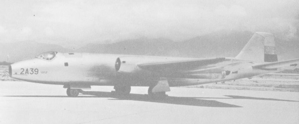
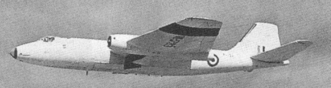
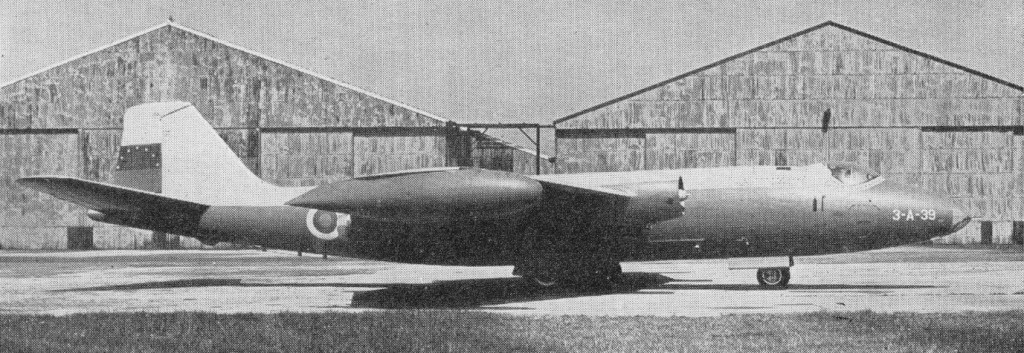
The Canberra was also built under licence in Australia, by the Government Aircraft Factory at Melbourne, for the Royal Australian Air Force (RAAF), where forty-eight examples (s/ns A84-201-248), known as the Mk.20 (48 built), were produced between 1953 and 1958.Five were later modified to Mk.21 dual trainers. The Mk.12 was a modified version of the RAF B(1)8 with an autopilot and extra navigation equipment. Following development work on B.2 WJ734, 1956 1957, eight B.2s were converted to T.11 radar targets for the training of AI radar operators for aircraft such as the Gloster Javelin. The nose section was elongated to take a radar with a distinctive conical radome. All eight T.11s were later converted, by the removal of the radar, for target facilities work as T.19s.
Canberra T.11
The T13 were type conversion trainers and T.17A EW/ECM variant. Along with the B(1).12s, the RNZAF ordered two T.13s, the equivalent of the RAF T.4. Both were handed on to India in 1970. The B.15 and B.16 were conversions of the B.6 for use by the Near East and Far East Air Forces. The main difference between the two variants was that the B.16 was fitted with the Blue Shadow radar system the two could he told apart by the trunking on the starboard fuselage above the nosewheel bay and the bomb bay. Provision was included for underwing air to ground unguided rockets and later for guided missiles to be carried. The first B.15 conversion flew for the first time on October 4, 1960. Eight B.15s were converted to E.15 target facilities aircraft. The first B.16 undertook its maiden flight during 1960. The T.17 was a dedicated electronic countermeasures (ECM) training aircraft, equipped with a variety of ‘nasties’ to teach defending forces what combat in ECM conditions would be like. The first conversion flew on September 19, 1965. T.17s equipped the unique 360 Squadron, manned by both RAF and Navy personnel. From 1986 six T.17s were upgraded with further ECM equipment to T.17A status; all were retired in 1994. On March 21, 1966, the first conversion of a B.2 to target tug status, TT.18, undertook its maiden flight. This was followed by 22 other examples, serving with the RAF and with the Fleet Air Arm. A Rusliton winch pack and towed target ‘bird’ could he carried under each wing. All eight T.11s were converted for target facilities work as T.19s. This involved simply removing the radar in the nose and replacing it with a concrete weight to keep the centre of gravity. The Canberra Mk.20 was a licence produced version of the B.2 built by Government Aircraft Factories (GAF) at Fisherman’s Bend, Melbourne, NSW for the Royal Australian Air Force (RAAF). The first aircraft, A84 201 flew on May 29,1953. A84 201, piloted by S/L P Raw, took part in the London to New Zealand air race (as No. 5) and came second, in an elapsed time of 24 hours 31 minutes. Five RAAF Mk.20s were later converted to dual-control trainers and redesignated as Mk.21s. Initially Mks.22 to 24 were allocated for further GAF produced Canberras, but this did not come about. The final Canberra variant in the home and Commonwealth system was the T.22 target facilities and radar instruction aircraft for the Royal Navy. These were conversions of PR.7s, the first example flying on June 28, 1973. Unlike other radar conversions, the T.22 boasted a somewhat elegant ‘nose job’.
A total of 1376 were built by the six manufacturers (including Avro, Handley Page and Short Bros) including 403 built under licence by Martin (in six variants) as the B-57. The B-57 saw combat over Vietnam beside other Canberras from Australia. 782 being supplied to the Royal Air Force. 48 were manufactured by the Government Aircraft Factory in Australia.
The Canberra was formally retired from RAF service on 28 July 1993 with the disbanding of No 39 (1 PRU) Sqn at RAF Marham in Norfolk. The squadron’s last three were PR.9. One of the pilots, Sqn Ldr Terry Cairns, at 61 was the oldest serving operational pilot in the RAF, was to retire too.
B(1) Engines: 2 x Rolls Royce Avon 101, 6500 lb thrust. Max speed: 570 mph @ 40,000 ft. Service ceiling: 48,000 ft.
B(I).6 Intruder variant
B(1)8 Two-seat long-range night interdictor or high-altitude bomber Engines: 2 x Rolls-Royce Avon 109, 7400 lb Wingspan: 63 ft 11.5 in Length: 65 ft 6 in Height: 15 ft 7 in Wing area: 960 sq.ft Empty weight: 23,173 lb MTOW: 56,250 lb Fuel capacity fuselage & wings: 2765 gal Wingtip tank fuel capacity: 2 x 244 gal Max speed: 541 mph at 40,000 ft Service ceiling: 48,000 ft Max range: 3630 mi Bomb bay capacity: 6 x 1000 lb or 3 x 1000 lb + 4 x 20mm guns
B(1)12 Engines: 2 x Rolls Royce Avon 109, 32.9kN / 7400 lbs thrust Max speed: 541 mph @ 40,000 ft. Length 65.5 ft. (19.96 m.) Wing span 64 ft. (19.5 m.) Height: 4.8 m / 15 ft 9 in Wing area: 89.2 sq.m / 960.14 sq ft Weight empty 23,170 lb. (10,510 kg.) Max take-off weight: 24925 kg / 54951 lb Max bomb load: 6,000 lb. (2,700 kg.) Max. speed: 827 km/h / 514 mph Ceiling: 48,000 ft. (14,600 m.) fully loaded. Range w/max.fuel: 5800 km / 3604 miles Range w/max.payload: 1300 km / 808 miles Armament: 4 x 20mm machine-guns, bombs, missiles Crew: 2
B(1)58
B.2 Wing span: 66 ft 11.5 in (19.49 m). Length: 65 ft 6 in (19.96 m). Height: 15 ft 7 in (4.75 m). Engines: 2 x RR Avon 101, 6500 lb. Max take off weight : 46712.9 lb / 21185.0 kg Max level speed: 517 mph (827 kph). Service ceiling : 47999 ft / 14630 m Range : 2308 nm / 4274 km. Crew : 3 Armament : 2722 kg Bomb.
B.2(TT)
B.6 Type: three seat light bomber. Engines: 2 x Rolls Royce Avon Mk 109 turbojets, 3402 kg (7,500 lb) thrust. Wing span: (excluding tiptanks): 19.51 m (64 ft 0 in). Length: 19.96 m (65 ft 6 in). Height: 4.75 m (15 ft 7 in). Wing area: 89.19 sq.m (960.0 sq ft). Empty wt: 10099 kg (22,265 lb). MTOW: 24041 kg (53,000 lb). Max speed sea level to 4570 m (15,000 ft): 973 km/h (605 mph) Max speed: 541 mph at 40,000 ft Service ceiling: 14630 m (48,000 ft). Combat radius (high, with full bombload): 1779 km (1,105 miles). Max range: 3790 mi Armament: internal bombload of 2722 kg (6,000 lb) and two underwing pylons for two 454 kg (1,000 lb) stores.
B.8 Engines: 2 x RR Avon Wingspan: 64 ft Length: 65 ft 6 in
Mk.20
Mk.21
B.Mk.82
PR.9 Type: two-seat tactical photographic reconnaissance aircraft Engines: two Rolls-Royce Avon 206 turbojets, 4559-kg (10,050-1b) thrust Maximum speed: 998 km/h (620 mph) / Mach 0. 94 Maximum Speed at 40,000 ft: 541 mph Service ceiling: 18290 m (60, 000 ft) Maximum range: 7240 km (4, 500 miles) Max Takeoff 54,950 lb Normal take-off weight: 22680 kg (50,000 lb) Wingspan 20.68 m (67 ft 10 in) Length 20,32 m (66 ft 8 in) Height 4.75 (15 ft 7 in). Armament: None
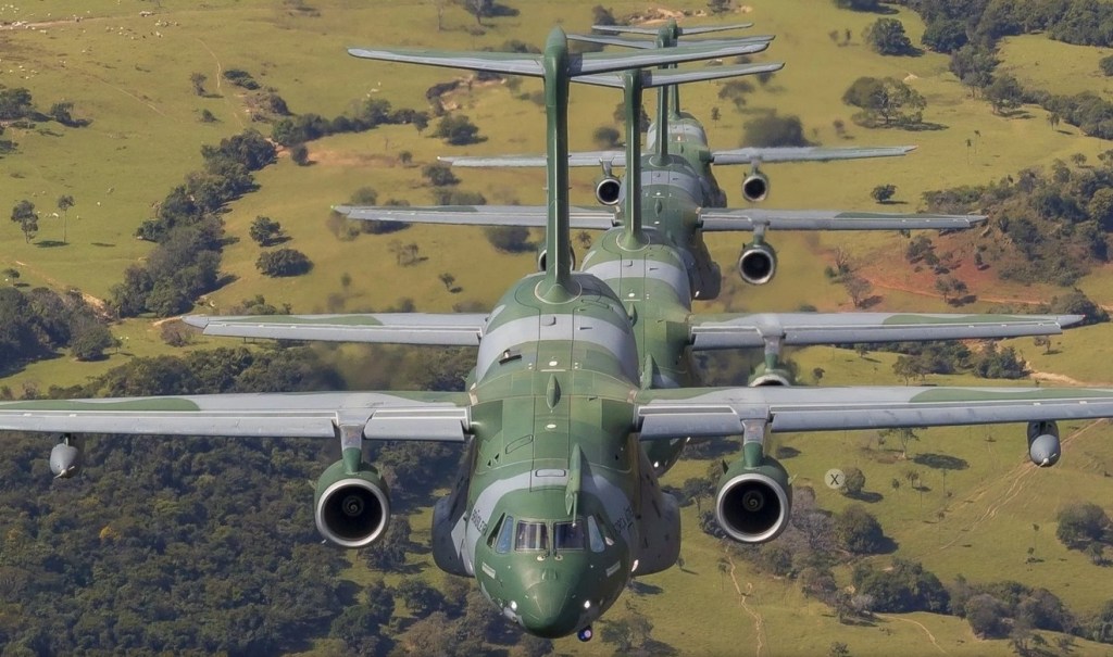
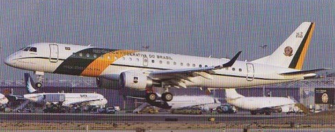
The KC-390 is a tactical transport and inflight refuelling aircraft. Powered by two specially designed Pratt and Whitney V2500-E5 engines, it can carry 26 tons of cargo, including vehicles like two M113 armored personnel carriers, or a UH-60 Blackhawk helicopter. The biggest aircraft produced in Latin America, it is designed to take off and land on semi-prepared and unpaved airfields. Portugal is a major partner in the KC-390 program, with some of its parts including the aircraft central fuselage being produced by Embraer’s subsidiary OGMA in Evora, about a hundred kilometers east of Lisboa. While Boeing was taking over the commercial aviation activities of Embraer, the two manufacturers agreed on a second joint venture to continue the production of the KC-390. Embraer should hold a 51% stake and Boeing ‒ the remaining 49%, of this new company.
Despite its smaller capacities in both range and payload compared to the new Airbus A400M Atlas, its price was attractive ($85 million compared to $165 million for Airbus transporter).
In 2014, the Brazilian Air Force ordered a total of 28 KC-390s with logistic support from the Brazilian manufacturer. It should progressively replace the C-130 Hercules within the FAB. In 2019 Embraer delivered the first KC-390 to the Brazilian Air Force (FAB) at the military base in Anapolis, in west-central Brazil.
It obtained the type certificate from the Brazilian Civil Aviation Authority (ANAC) in 2018.
In July 2019, Portugal placed a firm order for five KC-390 transport aircraft, becoming the first international customer for the plane. Embraer announced on July 11, 2019, that the Portuguese Council of Ministers had approved an order for five KC-390 multi-mission aircraft, a flight simulator, and logistical support, in a contract that should amount to €827 million. These aircraft are due to replace the Lockheed Martin C-130H of the Força Aerea Portuguesa (FAP), the Portuguese Air Force. They should be assigned to the 501 Transport Squadron “Bisontes”, based in Montijo Air Base (LPMT). The delivery should begin in 2023 and end by 2027.
Embraer has also received letters of intent from the Czech Republic (another partner in the program), as well as Argentina, Chile, and Colombia, for a total backlog of 35 aircraft.
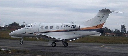
The Embraer Phenom 100 is a very light jet developed by Brazilian aircraft manufacturer Embraer. It has a capacity for 4 passengers in its normal configuration, but it can carry up to 6-7 passengers with a single crew. The Embraer Phenom 300 can carry 8 or 9 occupants with a flying range of 1,971 nautical miles.
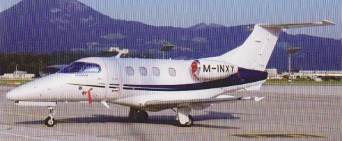
Embraer Phenom 100 M-INXY
Phenom 100 Engine: 2 x Pratt & Whitney Canada PW617F-E turbofans, 1695 lb / 770kg thrust Wingspan: 40 ft. 4 in / 12.30 m Overall Height: 14 ft 5 in / 4.4 m Overall Length: 42 ft. 0 in / 12.80 m Max take-off weight: 4750 kg / 10472 lb Empty weight: 3235 kg / 7132 lb Useful Load: 3384 lb Payload, Full Std. Fuel: 580lb Usable Fuel: 2804 lb Baggage Capacity: 67 cu. ft Max Certified Altitude: 41,000 ft / 12500 m Max Range: 1178 nm / 2182 km / 1356 miles Max. speed: 722 km/h / 449 mph Max Cruise Speed: 390 kt / Mach 0.70 Takeoff Distance, ISA: 3125 ft Takeoff Distance, 5,000 MSL, 25 deg C: 5926 ft Landing Distance: 2475 ft Max Demonstrated Crosswind: 17 kt Seating Capacity: 1+5/7 2009 Price: $3.6 million
Phenom 300 Engines: 2 x 1450kg Pratt & Whitney Canada PW535E turbofans Wingspan: 16.2 m / 53 ft 2 in Length: 15.9 m / 52 ft 2 in Height: 5 m / 16 ft 5 in Take-off weight: 7951 kg / 17529 lb Max. speed: 834 km/h / 518 mph Ceiling: 13716 m / 45000 ft Range: 3650 km / 2268 miles Crew: 1 Passengers: 6-8
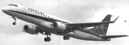
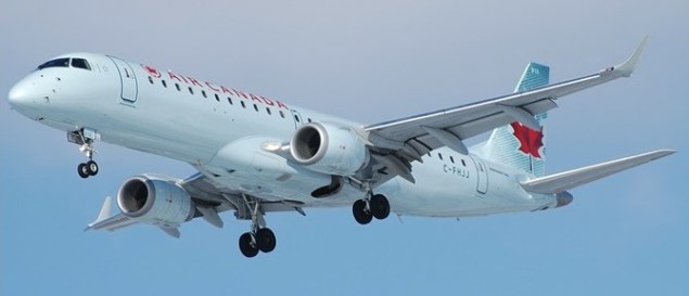
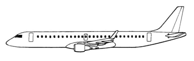
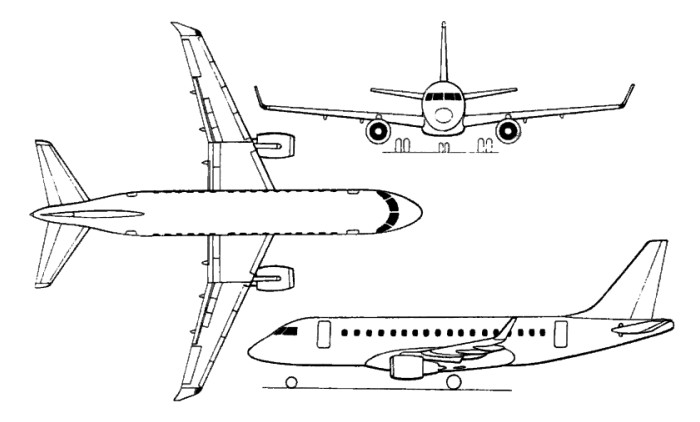
The ERJ-190 is a further stretch, by 6.25m, of the ERJ-170 to accommodate up to 104 passengers. The wing span is increased by 2.56m, GE CF34-8E-10 engines fitted, and strengthened landing gear. The –190 was available in Standard and Long-Range versions. The launch customer was JetBlue, who ordered 100, plus 100 options, on 10 June 2003. The Embraer 190 first flew in 2004 from Sao Jose dos Campos, Brazil. The fly-by-wire twin had 110 firm orders at the time. First delivery was in the third quarter of 2005. Formerly the ERJ-190-200, the ERJ-195 was a further stretch of the ERJ-190 by 2.41m to accommodate up to 110 passengers, also available in Standard and Long-Range versions. The first metal was cut on 23 August 2002, and first delivery in December 2004.
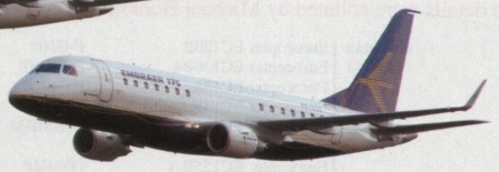
The ERJ-170 was announced in February 1999, and first orders announced on 14 June 1999. First rolled out on 29 October 2001, the first flight was achieved on 19 February 2002. C/n 0002 in Crossair colours was flown on 9 April 2002, by which time the first aircraft had completed 40 hours of test flying. C/n 0003 (first equipped with full Honeywell Pnmus Epic avionics suite) on 25 May 2002; c/n 0004 on 19 June 2002; c/n 0005 on 14 July 2002: and c/n 0006 on 27 July 2002.
It was announced at roll-out that the ERJ prefix was discontinued and that ERJ-190-200 was to be known as the Embraer 195; the intermediate Embraer 175 simultaneously revealed. The public debut was at the Regional Airline Association convention at Nashville, Tennessee 12 to 15 May 2002, followed by a European debut at Farnborough International Air Show on 22 July 2002, followed by a European demonstration tour comprising 18 flights totalling more than 100 hours. Six flying aircraft were scheduled to conduct a 1,800 hour flight test programme, culminating in CTA/JAA certification in November 2003. The original ERJ-170 has 70 seats, the ERJ-175 is five feet longer with 78. Each version of Embraer’s biggest regional jets come in a standard and long range version, plus the company is looking at a variant of the ERJ-170 as a corporate jet.
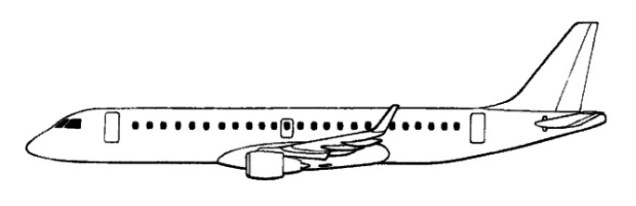
ERJ-170
The Embraer 175 first flew on 14 June 2003, from Sao Jose dos Campos, Brazil. The 175 is 70in (1.78m) longer than the 170 but for commonality retains the same cockpit and engines. The fuselage stretch is by means of two plugs to accommodate 78 to 86 passengers; offered in Standard and Long-Range versions.
ERJ-170 Engines: two 14,000 lb. General Electric CF34-8E Gross weight: 78,153 lbs Empty weight: 44,422 lbs Max cruise: 470 kts Range: 1,800–2,100 nm Service ceiling: 37,000 ft Takeoff field length: 5,499 ft Landing field length: 399 ft. Seats: 78