Fairey Ultra-Light Helicopter

During 1953 the War Office collaborated with the Air Ministry and the Ministry of Supply in the formulation of a specification for a simple and relatively inexpensive small helicopter for use by the Army for reconnaissance and other secondary duties such as casualty evacuation and training. The requirements were severe in terms of vertical climb performance, in tropical as well as temperate conditions, though endurance and speed were less stressed. The helicopter had also to be capable of being dismantled and assembled easily and quickly and of being transported on a standard Army three-ton truck.

The specification was sent to helicopter manufacturers in the British aircraft industry, with requests for tenders, and some half-dozen designs were submitted. Fairey eventually won the contract in July 1954 and a preliminary order for four prototypes, to specification H.144T, was placed. Two more were planned as a private-venture investment.

Fairey believed that a rotor-tip drive would be ideal for the Ultra-light Helicopter (as it was named), and preliminary studies showed that a tip-jet-driven version could be designed to do better than meet the requirements. A suitable small turbojet power source was already available in Britain — the French Turbomeca Palouste BnPe.2, which had been re-engineered with the turbine in Nimonic 90 alloy and was built under licence by Blackburn and General Aircraft.

To provide tip-jet air pressure in addition to residual thrust an oversize centrifugal compressor was fitted, and the excess delivery was bled off from the casing surrounding the annular combustion chamber. Untainted air was thus obtained at an initial maximum pressure of about 2.8kg/sq.cm. With this available pressure it would have been possible to design the rotor for operation using simple air jets, but, with their background of experience of fuel-burning pressure-jets, these were employed.

The compressed air was delivered, via a lagged duct, to the rotor head and, with metered fuel from the same tank as that supplying the gas turbine, and carried by centrifugal force to the tip-jets. There was a manually-operated blow-off valve for use when the engine was being ground-run, and, later in the test development, when rotor-power needed to be cut so that rapid autorotative descents could be made.

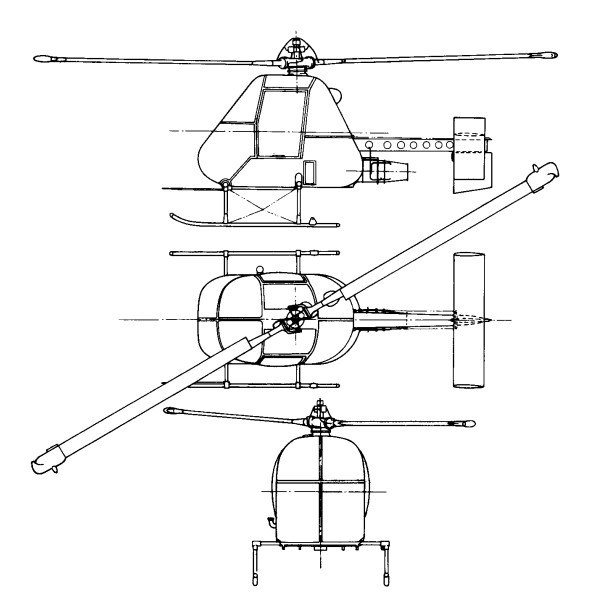
With the ample power available the rotor was designed to operate at high revolutions and to have a small diameter (8.53m), thus meeting the need for compactness. Two of the later variants were fitted with a slightly bigger diameter rotor (9.75m) so as to improve the performance. The small diameter of the rotor permitted the mechanical design and control system to be simplified. No drag hinges were employed and the two blades formed a see-saw combination without individual flapping hinges.

A direct tilting-head type of control was employed in the first prototype, but an irreversible hydraulically-powered system for the cyclic-pitch control was designed (together with a flexible pylon) and fitted to this and to later aircraft. The pilot’s controls were those normal for helicopters — with a collective-pitch lever which carried a twist-grip throttle for increasing engine revolutions and consequent air pressure for the tip-jets, and a stick for control in roll and pitch, but the rudder-pedal directional control was through a steel-skinned rudder on which the jet efflux impinged.

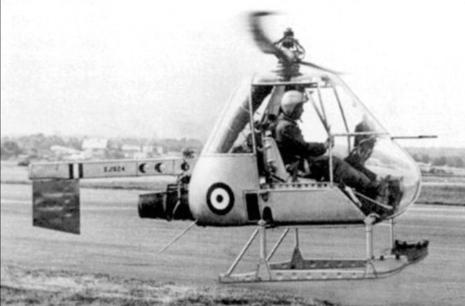
The Ultra-light was very simple in construction, the basis of which was a large light-alloy box containing the bag-type fuel tank. From the centre of this box rose the rotor pylon on which the remainder of the aircraft was, so to speak, hung. To the rear was attached a box-girder boom, under which the engine was slung, carrying the rudder — or rudders and an adjustable tailplane in later versions. This boom had a transport joint aft of the engine mounting. The crew’s seats (the observer facing aft in the proposed Army version) were on the basic box structure. The undercarriage consisted of a pair of skids attached to tubes running across the underside of the box.

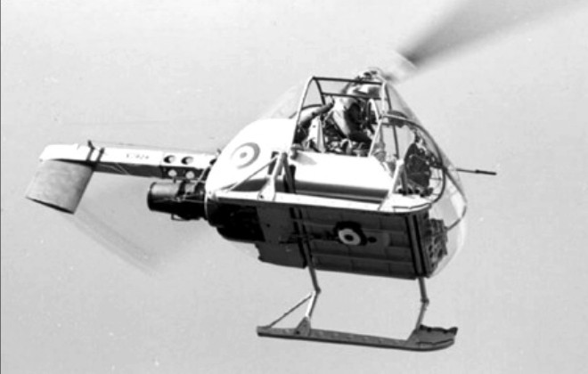
The initial flight of the first prototype, XJ924 (F.9423), was made at White Waltham by W. R. Gellatly, on 14 August, 1955 – only about 13 months from the start of design work — and it was shown and flown at the SBAC exhibition and display at Farnborough early in the following month.

Progress on the original basis was, however, to be overtaken by events. Before mid-1956 the Ministry of Supply had, for reasons of economy, ceased to support the Army project, and development of the Ultra-light was continued by Fairey on a private-venture basis, with considerable and expensive efforts to develop the original design and to sell it to prospective Service and civil operators.

There have been some considerable differences, among semi-official and other records, of the actual identities of the various Ultra-lights, of the total number completed and of the sequence in which they were produced. The principal difficulty in straightening the records has been caused by the fact that the original order ‘bookings’ were changed. Four (F.9423—9426) were planned to meet the original Ministry of Supply contract and two more (F.9427—8) were built by Fairey on a private-venture basis. After a certain amount of work had been done there were interchanges of components and then, following the Ministry cancellation, Fairey increased their private-venture programme.

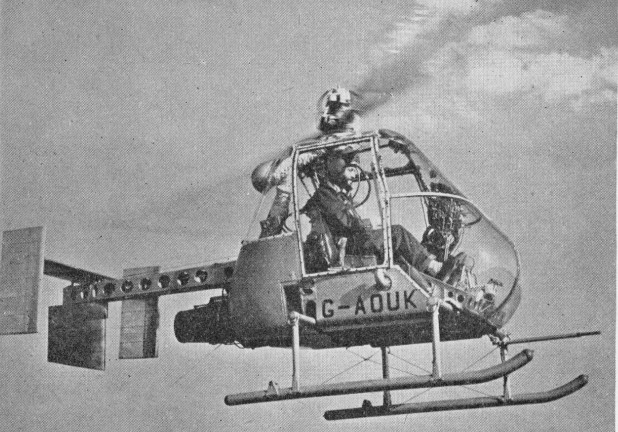
Some uncertain confirmation of the sequence of the completion of the Ultra-lights can be found in the press reports of the SBAC displays of the period. One such report for 1956 said that four had by then been built, the fourth being G-AOUK; another, after the 1957 display, said that five had been built, including G-AOUJ, which was at the show with G-AOUK, and that a sixth, G-APJJ, was under construction.

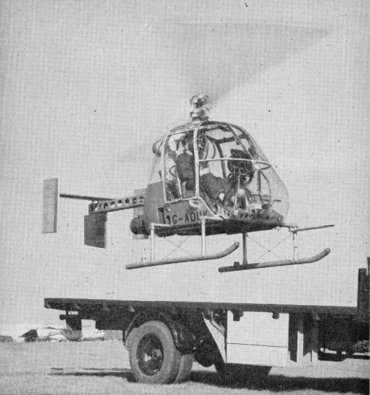
The serials XJ924, 928, 930 and 936 were allotted to the first four and three of the six were civil-registered following the withdrawal of official support. In order of c/ns, but not necessarily of completion or of initial flights, the six appear to have consisted of the following individual aircraft. The first prototype, XJ924 (F.9423), was the first to fly and was later modified with the hydraulic cyclic-pitch control and flexible pylon already mentioned. The second prototype, XJ928 (F.9424), became a Fairey de velopment aircraft for which a modified cabin was designed so that different loads, such as a stretcher case, could be accommodated; this was registered G-AOUJ and fitted with the hydraulic controls, flying for the first time in the revised form on 1 September, 1957. The third prototype, XJ930 (F.9425), was delivered to the Ministry of Supply. The fourth, XJ936 (F.9426), flown on 24 August, 1956, was the first to be fitted with the hydraulic controls and the flexible pylon; it appeared at die SBAC Display in September 1956 registered G-AOUK, and was the company’s principal demonstration and trials aircraft. Operating from the back of a standard truck, it demonstrated a rate of climb of 6.75m/s and a rate of descent in autorotation of 20m/s. The first of the two original private-venture aircraft, F.9427, was apparently used only for resonance tests and for ground-transport trials.

In the autumn of 1957 G-AOUJ underwent trials aboard the frigate HMS Grenville to determine the practicability or otherwise of operating small reconnaissance helicopters from platforms at sea. More than 70 landings and take-offs were made in winds of up to 62 knots, with the deck sometimes pitching through 3.05-3.66m and rolling up to 14 degrees each way. During 1958 both G-AOUJ and G-APJJ were being evaluated by the Royal Navy. The second, F.9428, was registered G-APJJ and flown initially in 1958; this had a cabin similar to that of G-AOUJ and was used for trials by the Royal Navy, operating from the deck of a destroyer, HMS Undaunted, before going to the Royal Aircraft Establishment, Bedford, and later to the College of Aeronautics at Cranfield.

In 1957 the Piasecki Aircraft Corporation of Philadelphia, USA, had obtained an option to build and the US Army was evaluating it for uses similar to those originally envisaged by the British authorities. Nothing, however, was to follow from these developments.

Typical of the continuous effort being put into Ultra-light demonstrations was the use, early in October 1958, of the stretcher-carrying G-AOUJ, flown by Peter Twiss, in a nuclear-war casualty exercise by the RAMC near Aldershot; the Rotodyne also took part in this exercise. Interest in the Ultra-light had been shown in Canada, and G-AOUJ, with its bulged nose to take a stretcher, and with special navigation and heating/ventilating equipment, was shipped out there later in 1958 for cold-weather trials and demonstrations by Lt-Cdr J. G. P. Morton. In the spring of that year a new draft specification was being drawn up for a version suitable for operation from small ships on anti-submarine duties both in attack (with a homing weapon) and communication roles. This proposal was based on a draft naval staff requirement and was a variation of the aircraft described in a brochure of April 1957 in which a naval strike version had been offered. The three civil-registered Ultra-lights were necessarily designed to meet airworthiness requirements and G-AOUJ and G-APJJ were duly certificated in the autumn of 1958. Work on the project was finally abandoned in 1959.

G-AOUJ has returned to the Helicopter Museum and restoration continued at Weston super Mare, but various parts, and drawings, are missing. A particular problem now is the swash-plate mechanism, of which there are no details.

Gallery

Engine: 1 x Turbomeca Palouste turboshaft, 185kW
Main rotor diameter: 8.61m
Fuselage length: 4.57m
Max take-off weight: 817kg
Empty weight: 290kg
Max speed: 153km/h
Hovering ceiling, IGE: 3109m
Range: 300km

Fairchild Republic A-10 Thunderbolt

Produced in reply to a specification of 1967, which called for a hard-hitting close-support aircraft, the Fairchild A-10A Thunderbolt II (YA-10A) first flew on 10 May 1972 and was selected by the USAF in preference to the Northrop A-9 on 18 January 1973 after a competitive flyoff, and received a contract for six A-10A aircraft, the first of which flew 15 February 1975. The Thunderbolt’s appearance derives from the care taken to enhance its survival prospects over the battlefield and incorporate maximum fire-power. Absorbing much of the centre fuselage is a GAU-8/A Avenger seven-barrel 30-mm cannon, the muzzle protruding slightly beneath the nose, which can be fired at the rates of 2,100 or 4,200 rounds per minute. The engine location is considered optimum for minimizing hits by ground-fire, and has the additional advantage that the wing and tail mask the infra-red emissions of exhaust gases and therefore affords some protection against heat-seeking SAMs. All of the A-10’s glass is bulletproof and the cockpit itself is surrounded by a heavy tub of titanium. Titanium armor protects both the pilot and critical areas of the flight control system. This titanium “bathtub” can survive direct hits from armor-piercing and high explosive projectiles up to 37 mm in size. The front windscreen can withstand up to a 23 mm projectile. Fire retardant foam protects the fuel cells which are also self sealing in the event of puncture.
The airframe has numerous constructional features resistant to battle-damage or conducive to swift repair, such as interchangeable (left or right) flaps, fuselage components, rudders, elevators and main landing gear legs. There are two primary hydraulic systems, each with manual back-up, and the landing gear can be extended under gravity if necessary. Well protected electronically by AN/ALQ-119 jamming pods, plus an AN/ALE-40 chaff and flare dispenser, the Thunderbolt carries a Pave Penny laser designation pod on a pylon to the right of the forward fuselage for accurate marking.

Fairchild Republic A-10 Thunderbolt Article

The first production A 10A Thunderbolt II flying on 21 October 1975. Entering service in early 1977, these single seat aircraft are powered by two 9,065 lb thrust General Electric TF34 GE 100 turbofan engines.

General Electric TF34 / Fairchild A-10 Thunderbolt Article

Armament comprises a seven barrel, 30 mm gun mounted in the nose, plus a maximum external load of 16,000 lb (7,257 kg) of weapons including air to surface missiles. The General Electric Aircraft Armament Subsystem (30 millimeter Gun System) is located in the forward nose section of the fuselage. The gun system consists of the 30 mm Gatling gun mechanism, double-ended link-less ammunition feed, storage assembly and hydraulic drive system. The General Electric GAU-8/A 30 mm seven barrel cannon, specifically designed for the A-10, provides unmatched tank killing capability. The gun fires armor-piercing projectiles capable of penetrating heavy armor. It also fires a high explosive incendiary round, which is extremely effective against soft skinned targets like trucks. The cannon fires at a rate of 4,200 rounds per minute.

Features of the design are very advanced avionics to enhance operational capability and provision of titanium 737 mph armour for the entire cockpit area.

Avionics equipment includes communications, inertial navigation systems, computer-aided fire control and weapons delivery systems, electronic countermeasures, target penetration aids and self-protection systems. The A-10 employs both electronic and infrared countermeasures against enemy weapons systems. The weapons delivery system incorporates a heads-up display that provides the pilot with references for flight control and weapons employment. The weapons delivery systems include head-up displays that indicate airspeed, altitude and dive angle on the windscreen, a low altitude safety and targeting enhancement system (LASTE) which provides constantly computing impact point freefall ordnance delivery; and Pave Penny laser-tracking pods under the fuselage.

Development of a night/adverse weather (N/AW) two seat version has been initiated, the prototype first flying in 1979. This is intended to allow the pilot to concentrate on control of the aircraft under night or adverse weather conditions, the second seat occupied by a weapons system officer to handle the electronics. The private-venture Thunderbolt N/AW (Night/Adverse Weather) was offered without success.

The A-10/OA-10 have excellent maneuverability at low air speeds and altitude, and are highly accurate weapons-delivery platforms. The A-10 has half the turning radius of the US Air Force’s other primary CAS aircraft, the F-16. After initially leaving a target, the A-10 can turn around and hit the same target again, all in around 7 seconds. Due to its large combat radius, the Thunderbolt II can loiter for extended periods of time, allowing for the coordination required to employ within yards of friendly forces. They can operate under 1,000-foot ceilings (300 meters) with 1.5-mile (2.4 kilometers) visibility. Using night vision goggles, A-10/ OA-10 pilots can conduct their missions during darkness.

The A-10 is capable of sustaining operations on unimproved airfields and the A-10’s rapid re-fueling and re-arming capability allows it to operate from forward bases close to the front lines. It is also capable of refueling in the air.

Altogether the USAF has received 713 aircraft, including A-10B dual control-trainers. Modelled on the A-10N/AW evaluator, the A-10B was in production featuring a second cockpit and taller fins.

The USAFs 33rd Tactical Fighter Training Squadron at Davis-Monthan AFB, Arizona, received its first Fairchild A 10A Thunderbolt IIs in February 1976.

The first combat-ready A-10A wing was the 345th Tactical Fighter Wing, based at Myrtle Beach, South Carolina, to which deliveries began on 20 March 1977. The last of 713 A-10s was handed over to the USAF on 20 March 1984. This was the end of aircraft manufacturing in Hagerstown and Washington County. A-10s were fitted with AIM-9L Sidewinder AAM dual rail adaptors, to allow four missiles to be carried in pairs.

The primary mission of the OA-10 is to act as forward air controller to coordinate and direct friendly air forces in support of land forces.
Northrop Grumman acquired the A-10 programme from Fairchild in 1987.
In 2000 preparations for the Precision Engagement Program (PEP) upgrade program began. PEP gives the A-10 the capability of deploying precision-guided weapons. The upgrade is carried out in two phases, called Spiral One and Spiral Two. The aircraft is designated A-10C. Between July and October 2004 the first A-10C underwent ground and instrumentation tests prior to the first flight in November 2004. In total 13 A-10C aircraft were for flight testing. The entire A-10A fleet is expected to receive the PEP upgrade. The last aircraft due to be modified before the summer of 2009.

Gallery

Fairchild A-10A Thunderbolt II
Engine: 2 x General Electric TF34-GE 100 turbofan, 9065 lb / 4112-kg
Wingspan: 57 ft 6 in / 17.53 m
Length: 53 ft 4 in / 16.25 m
Height: 4.47m / 14 ft 8 in
Wing area: 47 sq.m / 506.0 sq ft
Empty equipped weight: 11,321 kg / 24,959 lb
MTOW: 50,000 lb / 22,680 kg
Wing load : 96.97 lb/sq.ft / 473.0 kg/sq.m
Max speed: 439 mph / 706 kph
Combat limit: 704 km/h (438 mph) at 1525 m (5,000 ft)
Service ceiling 13,636m / 45,000 ft
Initial ROC: 1830 m / min / 6,000 fpm
Ferry range: 2454 sm / 3949 km
Combat radius: 930+ km
T/O run (to 15m): 780 m
Ldg run (from 15m): 715 m
Armament: 1 x 30 mm GAU-8/A Avenger seven-barrel cannon (1174 rds)
Pylons: 11 up to 7,258 kg / 16,000 lb
Fuel internal: 6225 lt.
Air refuel: Yes.
Seats: 1

OA-10A

Fairchild Engines J44

Fairchild Engine Division started studies for a small, inexpensive turbojet in 1946, for a guided missile the company was developing. In June 1947 the US Navy awarded a contract to develop such an engine to power an air-to-undewater torpedo-carrying missile. The engine, designated the J44, was America’s first expendable turbojet and was required to have a life of only 10 hours.

The Compressor was a mixed-flow, axial and centrifugal type with curved inducer vanes, and it was made of one piece of magnesium alloy casting that required no machining of the blades. Similary to the compressor, the diffuser section, with 3 rows of guide vanes, following the compressor was a single casting requiring no machining.

An annular combustion chamber was made from sheet metal and used in commercialy available oil burners. The single stage turbine had its blades welded on to a forged steel disc. A simple, stock stainless steel tube, with a welded flange at each end, formed the rotor connecting the turbine to the compressor.

There was a bearing before the compressor and aft of the turbine, and a fixed-area exhaust nozzle was used.

In August 1948 the XJ44 made its first run. The first flight was made in mid 1950 when it powered Fairchild’s Petrel Missile. As service trial proceeded, so problems with J44 where thrown up, most of them attribuable to over-simplified production. A lot of changes were required, and development of J44 was completed by October 1954 under designation J44-R-3.

The Improved engine was mounted on a Fairchild C-82 cargo aircraft, then later to each wingtips of the Fairchild C-123B cargo aircraft. Another use of the J44 was one the experimental Bell model 65 VTOL Aircraft.

The main usage of the J44 was to power the Firebee drone, although, with a specific fuel consumption of 1,55 it could not compete with Continental’s J-69 (Licence version of Turbomeca’s Marbore) and it was taken out of production by 1959.

Applications:
AQM-34B/C Firebee
AQM-41 Petrel
Bell Model 65
C-123 Provider

Specifications
Type: turbojet
Diameter: 0,56 m
Length: 2,24 m
Frontal area: 0,25 m²
Dry Weight, without accessories: 127 kg
Dry weight: 363 lb. (165 kg.)
Compressor: single stage centrifugal flow compressor
Combustors: annular combuster
Turbine: two-stage turbine
Fuel type: JP-4
Static thrust: 454 kg
Maximum thrust: 2450 lb. (10.9 kN)
Specific fuel consumption: 0.94 SFC
Thrust-to-weight ratio: 6.5:1

Fairchild NGT / Fairchild T-46 / Rutan 73 NGT

In 1977, the USAF began to reflect the launch of a program to find a successor to the Cessna T -37B trainer. At the end of 1981, a proposal for participation for a training aircraft of a next generation (NGT / Next Generation Trainer) was sent to Cessna, Fairchild Republic, General Dynamics, Rockwell International and Vought (associated with the German constructor Messerschmitt Bolkow Blohm). The specification was based on twin-turbofan, pressurised cockpit and to have a lower weight at T37. In terms of performance, the Air Force wanted an aircraft capable of a speed of 556 Km / h at 7620 m, and capable of taking off from a runway of 1524 m.

Designed as the Rutan 73, Fairchild Republic Company built a piloted 0.62 scale model of its New Generation Trainer design for the USAF, with the purpose of validating the handling qualities, control surface hinge moments, tail loads and spin characteristics of the full size aircraft.

Powered by a pair of 220 lb st (100 kgp) Microturbo TRS 18 turbojets, the scale aircraft was built by Rutan Aircraft under subcontract from Ames Industrial Corp on behalf of Fairchild and is largely of composite construction.

It was first flown at Mojave, California, on 10 September 1981 with Richard Rutan at the controls, and was expected to make about 35 flights by the end of November before being used for wind tunnel tests.

On July 2, 1982, Fairchild Republic was named the winner of the NGT program, which took the name of Thunder Piglet.

An initial contract was for two T- 46A (FSD) Nos. 84-0492 and 84-0493, 2 airframes for static tests, and an option for 54 of a planned total of 650. Deliveries were scheduled to begin in 1987 with a closure in March 1992.

The flight test program, and the development of pre-types took much longer than expected and led to the cancellation of the program March 13, 1987.

The prototype T-46 first flew in July 1986, but this was largely an academic move as the USAF had terminated the T 46 programme the previous March.

NGT
Engines: 2 x Microturbo TRS18
Wingspan: 6.70 m
Empty weight: 1,000 lb (454 kg)
Gross weight: 1,600 lb (726 kg)

T 46
Engines: 2 x Garrett F109 GA 100 turbo fans, 1,330 lb thrust

Eurofighter / EF-2000 / Typhoon

Eurofighter

The Eurofighter program started in 1992. The aircraft is a canard delta with a maximum take-off weight of 17,000kg, a wing area of 50sq.m, and two turbofans giving a total thrust of l80kN. The prototypes was to have either Turbo-Union RB.199 or General Electric F404 engines, but production aircraft were to be powered by Eurojet EJ.200s, which was being developed by a consortium consisting of Rolls-Royce, Fiat, MTU, and SENER. A multimode pulse-Doppler radar fitted, and armament was to include an internal gun plus AIM-120 Amraam and AIM-132 Asraam. The Eurofighter will be optimised for air-to-air roles but will have a secondary air-to-surface capability.

Eurofighter EF-2000 / Typhoon Article

The design features a delta wing design with canards set well forward of the wing. These features combined with two powerful EJ200 engines and digital flight control systems produce a highly agile fighter.
The Eurofighter design has been named Typhoon by the Royal Air Force, dropping the EF2000 project name. Spain and Italy and the industry have taken on the name Typhoon as well.
The first prototype DA.1 flew in Germany on 27 March 1994. Seven development aircraft (DA) were built, as well as several Instrumented Production Aircraft for evaluation, weapons and systems testing.
Tranche 1 production aircraft are used primarily for evaluation, instructor and pilot conversion training, but have also entered operation attending large-scale exercises and taking on the air defense role.

Eurofighter EF-2000 Typhoon FGR4

A total of 620 aircraft have been ordered by the participating countries. Delivered aircraft were being upgraded to the latest Tranche 1 production standard, Block 5, to bring all Tranche 1 aircraft to a near-common standard, including limited air-to-ground capability with a selection of precision guided weapons.
The RAF is primarily replacing the Tornano F.3 air defence fighters, but has also retired its remaining Jaguar fighter-bombers. The Eurofighters for the Luftwaffe will replace its fleet of F-4F Phantom IIs (and fill the gap left by the retirement of the MiG-29 Fulcrum-C). Italy has retired its last F-104ASA Starfighters and returned the leased RAF Tornado F.3s. However because of the delays in the program, it had to lease ex-USAF F-16 ADF to fill the gap. It has equipped its third wing with the Typhoon. Spain has equipped its first squadron with the Eurofighter, but the Mirage F1 aircraft have been put through a modernisation program to keep them in service for some years.


Although Greece was the first to sign a contract for delivery of a first batch of Eurofighters, having initially ordered 60 aircraft with an option for 30 more. However the contract was cancelled and any order would be postponed until after the Olympic Games. It remains to be seen if Greece would renew the Eurofighter contract.
Austria ordered 18 Eurofighter Typhoons, with an option for six more, the contract was revised in 2007 and the number was reduced to 15 aircraft of Tranche 1 standard. .
Saudi Arabia signed a declaration of understanding with regards to the purchase of 24 Typhoons in Trache 2 standard to replace its Tornado ADV fleet. Follow-on is expected as it is reported Saudi Arabia has a requirement for at least 72 Typhoons.

The Eurofighter Typhoon was once the epitome of European airpower. Fast, agile, and lethal, it was a Cold War-era air superiority fighter optimized for an age when speed, maneuverability, and firepower conferred dominance in the skies.
But as air superiority and supremacy is increasingly a function of stealth, sensor fusion, and network-centric operations, the Typhoon is beginning to show its age by 2025. It is not yet entirely obsolete, but it is fighting an increasingly desperate rearguard action against the steadily advancing forces of future aerial warfare.
The uncomfortable reality is that fourth-generation platforms like the Eurofighter Typhoon, no matter how upgraded, are becoming increasingly less able to hold their own in high-intensity conflicts.
With a powerful twin-engine design, excellent thrust-to-weight ratio, and canard-delta aerodynamics, it outmaneuvers most of its contemporaries. Its supercruise capability gives it an edge over other fourth-generation jets, allowing it to maintain supersonic speeds without afterburners.
Armed with the Meteor missile, one of the most advanced air-to-air weapons out there, it poses a serious threat to any enemy aircraft that enters its engagement range. Recent upgrades, such as the integration of the CAPTOR-E AESA radar and enhanced electronic warfare suites, have further extended its lifespan and improved its lethality and survivability.

Yet, despite all of these upgrades, the Typhoon remains fundamentally disadvantaged against fifth-generation stealth aircraft. The transformation of air combat over the past two decades has been revolutionary. It is no longer about raw flight performance or even missile range – rather, it is about situational awareness, sensor fusion, and the ability to strike pre-emptively without being seen.
A stealth fighter like the F-35 or China’s J-20 does not simply enjoy reduced radar visibility; it enjoys advantages derived from the fact that it is a node within an information network, receiving data from satellites, drones, and other assets that radically enhance its survivability and lethality.
The simple fact is that in a contested environment, a Typhoon will be detected, targeted and shot down long before it can locate its stealthy adversary. Even with AESA radar and electronic countermeasures, it cannot change the fundamental physics of radar cross-section reduction and detection timelines. Air combat has always favored the pilot who sees first, shoots first, and eliminates the enemy before they can react. In that equation, the Typhoon is on the losing end against modern stealth fighters.

Gallery

Variants:
DA
IPA
Tranche 1 / RAF F.2 single-seat / T.1 two-seat
Tranche 2

Typhoon
Engines: two 90 kN (20,250 lb st) Eurojet EJ200 afterburning turbofans
Length 15.96m (52 ft 4 in)
Height 5.28m (17 ft 4 in)
Wing span: 10.95m (35 ft 11 in)
Aspect ratio : 2.21
Wing area: 551.117 sq.ft / 51.2 sq.m
Empty weight: 10.995 kg (24,239 lb)
Max Take-Off Weight: 23000 kg (50,700 lb)
Max level speed clean at 11000 m (36,0069 ft): Mach 2.0 / 2125 km/h (1,321 mph)
Landing speed: 130 kt / 241 km/h
Service ceiling: 15,240+m (50,000+ ft)
g limits +9/-3
Runway requirement: 700m (2,300ft)
Armament: one Mauser Mk27 27mm cannon/ 150rds; up to 6500 kg (14,330lb) ordnance
Hardpoints: 13
Auxiliary fuel: three tanks
Crew: 1

DA.1
Engines: 2 x Eurojet EJ.200 turbofans, total thrust of l80kN.
MTOW: 17,000kg.
Wing area: 50sq.m.

DA.2

DA.7

Eurocopter X3

Eurocopter began a X3 flight testing programme in September 2010 that combines the vertical takeoff and landing capabilities of a helicopter with an aircraft’s fast cruise speeds of more than 220 kts. After achieving the initial true airspeed goal of 180 kt (333 km/hr) in November 2010 at a reduced level of engine power, the X3 underwent its planned gearbox upgrade and safety inspection. Since returning to flight, the X3 quickly demonstrated its performance at full engine power, including impressive climb and descent rates as well as manoeuvrability while also confirming the hybrid propulsion system’s capabilities for acceleration and deceleration.
The hybrid aircraft has low vibration levels without the use of passive or active anti-vibration systems, providing flight characteristics comparable to those of the best traditional design helicopters currently in service.
Eurocopter’s X3 hybrid helicopter demonstrator had an original speed target of 220 kts, The X3’s speed milestone was reached on 12 May 2011 during stable level flight; the hybrid demonstrator maintaining a true airspeed of 232 kts (430 km/hr) for several minutes. This occurred during only the third mission after a scheduled upgrade that integrated the X3’s definitive gearboxes, enabling it to operate at full power.

The X3 uses a primary rotor like a helicopter for vertical operation and a pair of outrigger engines for forward motion. A pair of turboprop engines push it up to speed. It could only accommodate two people.

In 2011, the X3 broke records by achieving a cruising speed of 267 mph using only 80% of its power. Three years later, in June 2013, it reached a top speed of 300 mph before the pilot reined it down to a cruise of 293 mph.

After 199 test flights from which engineers gleaned reams of data, the airframe was retired and now lives a as an exhibit at the Bourget National Air and Space Museum outside of Paris.

Eurocopter MRH 90

The MRH 90 is the first true fly-by-wire helicopter and is equipped with a Forward Looking Infra Red system for flight in low light and has the same pilot helmet-mounted sight and display as used in the Tiger Armed Reconnaissance Helicopter.

The Australian Defence Force ordered an additional 34 MRH 90 to bring the total to 46. Eurocopter subsidiary Australian Aerospace was to assemble 42 at its Brisbane facility.

Length 16.09m
Width 3.63m
Height 4.16m
Range (combat load) 290nm
Max passengers 18
Max Payload 8800lbs
Armament 7.62mm Machine Gun

Eurocopter EC-225 Super Puma / Eurocopter EC-725 Cougar

Eurocopter EC-725 Cougar (military Super Puma Mk.2).

The Eurocopter EC 225 civilian and its EC 725 militarized variant is an improved version of the Puma family line. This system first flew in November of 2000 and features a five-bladed main rotor assembly. It also has a larger cabin with newer Makila 1A4 turboshaft engines featuring FADEC (Full Authority Digital Engine Control), a greater Maximum Take-Off Weight (MTOW) and revised EFIS avionics.

Eurocopter EC225 Super Puma

Eurocopter EC-635

The EC 635 Military version of the EC 155 mockup was a conversion of first preproduction EC 135 (D-HECX). Offered (unsuccessfully) to South Africa and unveiled at Aerospace Africa Air Show on 28 April 1998. First customer was Portuguese Army, which ordered nine EC 635T1s on 22 October 1999 for delivery from June 2001. However, these retrospectively cancelled on 14 August 2002, following delay in post-delivery modifications; all sold to Jordan which, in March 2003, increased its order to 16.

The EC 635 underwent testing with FN Herstal HMP 400 12.7mm machine gun, Giat NC621 20mm gun and 12-round 70mm rocket launcher.

EC-635 D-HECM (c/n 0529), the first of the type for the Swiss Air Force, first flew, from the Donauwörth facility in Germany, on 23 May 2007.