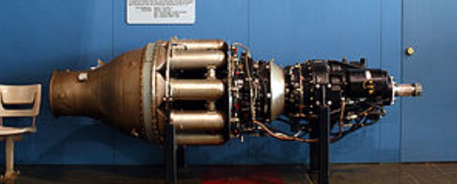
The first American turboprop engine was the General Electric XT31, first used in the experimental Consolidated Vultee XP-81. The XP-81 first flew in December 1945, the first aircraft to use a combination of turboprop and turbojet power.
The T31 engine was the first American turboprop engine to power an aircraft. First run in May 1945, it made its initial flight in the Consolidated Vultee XP-81 on 21 December 1945. The T31 was mounted in the nose; a J33 turbojet engine mounted in the rear fuselage provided added thrust. The T31 was also used on the Navy XF2R-1, similarly powered by a turboprop/turbojet engine combination.
The engine was to have been flown experimentally on a Curtiss XC-113 (a converted C-46), but the experiment was abandoned after the XC-113 was involved in a ground accident. Only 28 T31s were built; none were used in production aircraft, but improved production turboprop engines were developed from the technology pioneered by the T31.
A derivative of the T31, the General Electric TG-110, given the military designation T41, was ordered but subsequently cancelled.
Applications: Consolidated Vultee XP-81 Curtiss-Wright XC-113 XF2R Dark Shark
Specifications:
XT31 Type: Turboprop Dry weight: 1,980 lb Maximum power output: 2,300 shp (design) at 13,000 rpm. (1,145 propeller rpm)
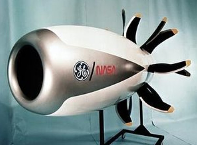
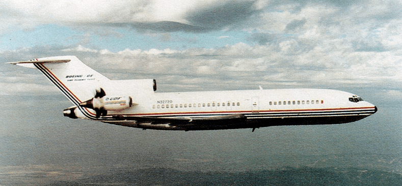
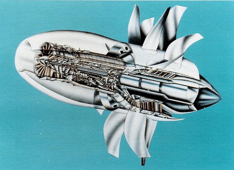
The General Electric GE36 was an experimental aircraft engine, a hybrid between a turbofan and a turboprop, known as an Unducted Fan (UDF) or propfan. The GE36 was developed by General Electric Aircraft Engines and first run in 1986.
A General Electric F404 military turbofan was used as the basis of the GE36. The F404 mixed exhaust stream discharged through a seven-stage low pressure (LP) turbine, where each stator ring was ‘unearthed’ and free to move in the opposite direction to that of the rotors. One set of open rotor, variable pitch, fan blades was connected to the LP turbine rotor system, while the other set was connected to the contra-rotating LP turbine stators. The scimitar shape of the fan rotor blades enabled high flight speeds (about Mach 0.75) to be obtained. GE used a low speed, (effectively) 14 stage, LP turbine, rather than a conventional high speed LP turbine and reduction gearbox, to drive the fan rotor blades.
Although the engine demonstrated an extremely low specific fuel consumption, cabin noise levels were a problem, even though the engines were mounted at the rear of the test aircraft.
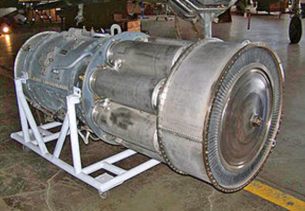
The General Electric/Allison J35 was originally developed by General Electric (GE company designation TG-180) in parallel with the Whittle-based centrifugal-flow J33, and was the United States Air Force’s first axial-flow (straight-through airflow) compressor engine. The J35 was fairly simple, consisting of an eleven-stage axial-flow compressor and a single-stage turbine. With the afterburner, which most models carried, it produced 7,400 lbf.
Like the J33, the design of the J35 originated at General Electric, but major production was by Allison.
The J35 first flew in the XP-84 in 1946. Late in 1947, complete responsibility for the production of the engine was transferred to the Allison Division of the General Motors Corporation. Some J35s were built by GM’s Chevrolet division. More than 14,000 J35s had been built by the time production ended in 1955.
The J35 was used to power the Bell X-5 variable-sweep research aircraft and various prototypes such as the XB-43 Jetmaster, XB-45 Tornado, Convair XB-46, XB-47 Stratojet, Martin XB-48, and Northrop YB-49. It is probably best known, however, as the engine used in two of the USAF’s leading fighters of the 1950s, the F-84 Thunderjet and the F-89 Scorpion.
A larger development of the engine was later produced as the Allison J71, producing around 10,000 lbf.
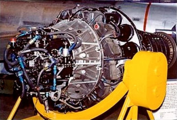
The J33 was originally developed by General Electric as a follow-on to their work with the designs of Frank Whittle during World War II. Their first engine was known as the I-A, but after major changes to adapt it to US production and to increase thrust, it started limited production as the I-16 in 1942, the 16 referring to its 1,600 lbf (7,100 N) thrust. Full production started as the J31 when the United States Army Air Forces introduced common naming for all their engine projects.
Along with the I-16, GE also started work on an enlarged version, known as the I-40. As the name implied, the engine was designed to provide 4,000 lbf / 18 kN (ending at 4,600 lbf (20 kN) with an additional low-altitude boost to 5,400 lbf / 24,000 N with water-alcohol injection). Design work started in mid-1943 and the first prototype underwent static testing on January 13, 1944.
Lockheed was in the midst of the XP-80 project at the time, originally intending to power their design with a US-produced version of the Halford H-1 of about 3,000 lbf (13 kN). Production of the H-1 ran into delays, and since the I-40 would dramatically improve performance, plans were made to fit the prototypes with the I-40 instead.
The I-40 became important to the USAAF’s plans when the I-16 powered P-59 was skipped over in favor of the I-40 powered P-80 as the US’s first production jet fighter. In 1945 the license to actually produce the engine was not given to General Electric, but Allison instead. Allison, working largely from government-owned wartime factories, could produce the engine in quantity more quickly and cheaply.
By the time the production lines were shut down Allison had built over 6,600 J33’s, and General Electric another 300 (mostly the early runs).
In 1958, surplus J33s were used in jet donkeys pushing dead loads at 200 knots to test aircraft carrier arresting gear cables and tailhooks at Lakehurst.
The General Electric/Allison J33 was a development of the General Electric J31, enlarged to produce significantly greater thrust, starting at 4,000 lbf (18 kN) and
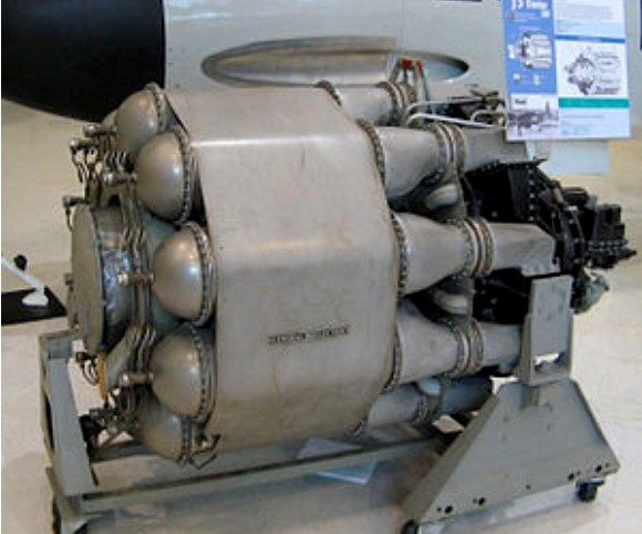
The General Electric J31 was the first working jet engine produced in the United States and also the first jet engine to be produced in quantity there.
The J33 was originally developed by General Electric as a follow-on to their work with the designs of Frank Whittle during World War II. The J31 was essentially a production version of the prototype Whittle W.1 that had been sent to the US after the Tizard Mission successes. General Electric’s extensive experience in turbocharger production made them the natural choice for producing the engine, which they initially referred to as the I-16, I-A referring to the original prototype. After major changes to adapt it to US production and to increase thrust, it started limited production as the I-16 in 1942, the 16 referring to its 1,600 lbf (7,100 N) thrust. The United States Army Air Forces later decided to standardize all their jet engine naming, at which point the I-16 became the J31. Full production started as the J31.
Like the W.1, the I-16 produced 1,650 pounds force (7.3 kN) of thrust and weighed about 850 lb. Production started for the P-59 Airacomet in 1943, and by the time the lines shut down in 1945, a total of 241 had been built. GE also used the basic design to produce the much larger I-40 with 4,000 lbf, but this design was passed on to Allison as the J33, much to GE’s chagrin and another derivative of the J31, the General Electric I-20, given the military designation J39, was ordered but later cancelled.
Applications: Bell P-59 Airacomet Ryan FR Fireball Ryan XF2R Dark Shark
Specifications:
J31 Type: Centrifugal compressor turbojet Length: 72 in (1,828.8 mm) Diameter: 41.5 in (1,054.1 mm) Dry weight: 850 lb (385.6 kg) Compressor: Single-stage double-sided centrifugal Combustors: 10 reverse-flow can Turbine: Single-stage axial Fuel type: Kerosene (AN-F32) or 100/130 gasoline Oil system: pressure spray, wet sump with scavenge cooling and filtration, oil grade 60 S.U. secs (10.2 cs) at 38°C Maximum thrust: 1,650 lbf (7.33 kN) Overall pressure ratio: 3.8:1 Turbine inlet temperature: 1,220 °F (660.0 °C) Specific fuel consumption: 1.2 lb/lbf/hr (0.1223 kg/kN/hr) Thrust-to-weight ratio: 1.887 lbf/lb (0.018.5 kN/kg)
J-31-GE-1 Type: Centrifugal flow turbojet Length: ~72 in (1,828.8 mm) Diameter: ~41.5 in (1,054.1 mm) Dry weight: ~865 kg (1,910 lb) Compressor: Single-stage double-sided centrifugal flow Combustors: 10 reverse-flow can Turbine: Single stage axial flow Fuel type: Kerosene Maximum thrust: ~1,610 lbf (7.2 kN) Overall pressure ratio: ~4.5:1 Fuel consumption: ~1980 lb/hr (~898 kg/h) Specific fuel consumption: ~1.23 lb/hr/lb (~34.84 g/s·kN) Thrust-to-weight ratio: ~1.861:1
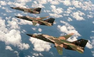
During the 1950s, the general development of tactical aircraft moved in the direction of greater performance, at the expense of long field length, high cost and inflexibility. By 1959, USAF Tactical Air Command was ready to plan a new aircraft, in the first instance to replace the F 105, which would combine many new features and offer outstanding capability and versatility. In particular, it would be the first combat aircraft to have a variable sweep (so called ‘swing wing’) aerofoil to match the conflicting needs of high lift at takeoff or landing, low speed efficiency in subsonic cruise or loiter, and minimum-area minimum span shape for low level attack at the highest possible speed.
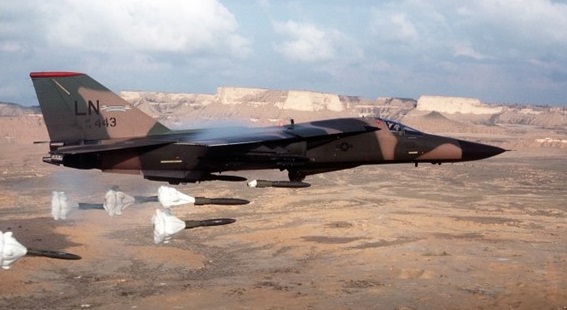
What caused great difficulty was that, in the first place, the TAC planners set their sights too high in drafting Specific Operational Requirement 183, so that the figures could not be met. Second, the US Navy in 1959 also wanted an important new aircraft, a Fleet Air Defense Fighter, carrying a powerful radar and long range missiles. In 1960, the new Secretary for Defense, Robert S McNarnara, studied the two requirements and, in his words, ‘was struck by the high degree of similarity’. After discussion with his civilian aides, he decided to urge that the USAF and Navy work towards a common aircraft design. His advisors suggested that such a move, called ‘commonality’, would save a billion dollars. After the longest and most hard fought procurement battle in history, General Dynamics Fort Worth won over Boeing¬ Wichita, the choice being announced on November 24, 1962. There had been an unprecedented four rounds of detailed technical and cost bidding, and in each round the consensus of customer opinion had, it was claimed, favoured Boeing. The Wichita team had not only offered what was in some respects a superior product, but they had consistently quoted a lower price. After Pentagon adjustments, the quotation for research, development and production of a total of 1726 aircraft (231 of them to be of the navy version) by Boeing was $5387 million and that from GD was $5803 million. As soon as the decision was announced, there was a storm of protest in Washington. It grew, as there was a prolonged public enquiry, and the position was later exacerbated by trouble with the winning aircraft and consistent failure to meet the impossible specification. GD flew the first F 111A on December 21, 1965, and on the second flight operated the wings through the whole range of sweep, from 16 degrees to 72.5 degrees, ahead of schedule. An attempt to win a further bonus by exceeding Mach 1 was thwarted by severe engine compressor stall. The chosen engine, the Pratt & Whitney JTF10A 20, later given the military designation TF30 P 1, had been selected because it was a typically conservative Pratt & Whitney product. It was likely to deliver the modest specified performance maxi¬mum thrust with full afterburner was only 8390 kg (18500 lb) and give little trouble. It was the world’s first afterburning turbofan, calculated to combine high performance in the supersonic dash mode with excellent fuel economy in the subsonic cruise regime. The new feature of afterburning in both the core and fan streams gave little difficulty, but the installed powerplant was a disaster. Part of the problem was that, to save weight, General Dynamics had cut the inlet ducts back under the wings, and turbulent air was hitting the aerodynamically tricky compressor. It took considerable redesign of the engine and a total redesign of the inlet system, with a so-called triple flow 3 inlet, before the installation would work properly in all flight regimes. Further extremely severe trouble was met with aircraft weight and drag, so that at first the specified range was not even approached. During 1965 66, using 18 development aircraft, the Fort Worth team restored some of the lost range by increasing the internal fuel capacity. This naturally raised the gross weight sharply, and accentuated the already marginally acceptable large size and weight of the F 111B Navy fighter version, co-producer of which was Grumman. After years of toil the F 111B came to an end in 1968 simply by the refusal of Congress to vote any further funds. This removed the captivating goal of commonality, leaving the F 111A not quite the way it would have been designed for the USAF alone. A further fundamental point is that, partly owing to confusion over the concept of a ‘fighter’, the F 111 had been planned to replace all the tactical aircraft of the USAF, including fighters, and attack bombers and fighters of the navy. In fact, the resulting aircraft was in no way a fighter, though with different radar and missiles it might have been a long range intercepter. Though it had been given an internal gun, a 20 mm (0.79 in) M61 Vulcan, with its ammunition drum occupying the internal weapon bay instead of bombs, this gun had no air combat role and was removed from most of the delivered aircraft. The F 111A was instead a bomber. Though the internal bay had been included to carry two B61 nuclear bombs at supersonic speed in a low level or high altitude attack, the main weapon load has always been hung externally. There are eight hard points on the wings, and all are on the swinging part; there are no pylons on the fixed gloves or fuselage. The outer pylons are seldom fitted, and a normal weapon load is 24 bombs (eight triplets) of a nominal 226 kg (500 lb) on the four inners, a true weight of 6314 kg (13920 lb). The F 111A can also carry a wide range of cluster bombs, dispensers, ALQ 119V ECM pods and other stores.
The F 111A was the first tactical aircraft to go into service with blind first pass strike capability. The equipment needed includes a large multi mode nose radar (in most versions, by General Electric), with two small dishes serving a terrain following radar (TFR). The right seater is an observer or weapons system officer, with comprehensive navigation and radar displays, and in the terrain following mode it is his job to keep the pilot constantly informed about obstructions or other objects coming up ahead.
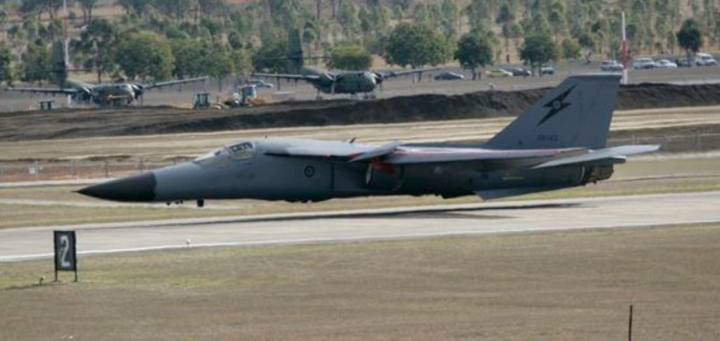
The F-111 crew sits side-by-side, both are enclosed in a capsule which separates from the aircraft in an emergency, a proven escape system which obviates the need for ejection seats. In addition to 17 F-111As for development work, 141 went to the 4881 Tactical Fighter Squadron at Nellis AFB in July 1967, for intensive trials evaluation. With four tandem triplets of bombs, the maximum speed proved to be about 925 km/h (575 mph) at typical attack height; with two bombs in the weapon bay and nothing exter¬nal it was Mach 1.1, roughly according with SOR 183. At height the attainable speed in the clean condition was about Mach 2. Ferry range with six 2271 litre (500 Imperial gallons) drop tanks is about 6400 km (3980 miles). These were powered by two 8392kg afterburning thrust Pratt & Whitney TF30-P-3 turbofans. In March 1968, six F-111As of the wing’s 428th Tactical Fighter Squadron under Colonel Ivan H. Dethman were rushed to Takhli, Thailand, to begin combat operations against North Vietnam. The first three aircraft launched on the first three missions vanished for ever, although the detachment later flew 55 missions successfully. The USAF discovered, as a prisoner of war from this deployment would later confirm, that a tailplane problem caused uncontrollable pitch-up and roll. A separate fatique problem caused wing spar cracks and, in 1969, resulted in the loss of an F-111A when its wing was torn off. In 1969, the entire fleet of 300 aircraft was grounded while an exhaustive structural review programme remedied these problems. GD delivered 141 of the A model with TF30 3 engines, including two YF 111A air¬craft rebuilt from a cancelled British order for 50 F 111K. The Strategic Air Command’s FB-111A, operating with two wings, is a very long-range variant powered by two 9230kg afterburning thrust Pratt & Whitney TF30-P-7 turbofans, with modified inlets, long-span wing, and provision for nuclear or thermonuclear weapons or up to 50 340kg HE bombs; 76 FB-111As were built. The Royal Australian Air Force bought 24 F 111C with long span wings and stronger landing gears, these suffering a nine year delay due to structural problems and contract uncertainties and were delivered to Australia in 1973 after lengthy delays. The F-111C differs from the F-111A model in having a longer-span wing and stronger landing gear. Four F-111Cs have been converted to the reconnaissance role and the remainder, like many USAF ‘Aardvarks’, are being equipped with Pave Tack pods for laser acquisition of ground targets.
One of six RAAF F-111C at Red Flag 07
The Royal Australian Air Force operates three versions of the F-111:
the F-111C strike fighter
the unique RF-111C, modified for photo-reconnaissance work, and
ex-US Air Force F-111G’s, which help ensure Australia maintains its strike capability until the F-111 is retired.
The F-111D, F-111E and F-111F are variants of what has become a highly specialised long-range strike aircraft ideal as a counter to the Soviet Sukhoi Su-24 and as a means of hitting targets in eastern Europe from the British Isles. These variants are located respectively at Cannon AFB, New Mexico, RAF Upper Heyford and RAF Lakenheath, England. Production amounted to 96 F-111D, 94 F-111Es and 106 F-111Fs. The F-111H was a proposed strategic bomber once perceived as an ideal interim step for the 1980s when it appeared that the Rockwell B-1 had been cancelled. The F-111K was the intended version for the UK’s Royal Air Force. Neither was built, and total production amounted to 562 airplanes.
The F 111D, of which 96 were built, has the slightly more powerful 8891 kg (19600 lb) TF30 9 engine and the totally different ‘Mk II’ avionics, with mainly solid state digital circuits. The F 111E (94) had only improved engine inlets, otherwise resembling an A. The final F 111F version (106) has the vastly improved TF30-100 engine, rated at 11385 kg (25100 lb) thrust, and a simpler and cheaper version of the F 111D avionics. In 1967 some $118 million was spent in the development of a multi sensor reconnaissance pallet which was test flown in the eleventh F 111A. There remained an intention to rebuild some or all D models as RF-111Ds. Since 1976 much further development has been in progress to update this vital and powerful tactical attack force. Grumman has been developing the EF 111A electronic warfare aircraft by transferring the ALQ 99 tac jamming system of the EA 6B Prowler to rebuilt F 111A airframes. In 1965 McNamara, before leaving the Pentagon, announced that 210 strategic bomber versions designated FB-111A would be bought to replace Strategic Air Command’s B 58 and older B 52 bombers. Increased costs caused the eventual force to be terminated at only 76, and these equip two small (30 aircraft) wings, styled Bomb Wing (Medium), the 380th at Plattsburgh and 509th at Pease. The FB 111A has a modest engine, the 9230 kg (20350 lb) TF30 7, a so called ‘Mk 2B’ avionics system, and the long span wing and strong landing gear. It can carry a theoretical bombload of 50 free fall bombs of nominal 340 kg (750 lb), actually weighing a total of 18710 kg (41250 lb). 76 FB-111As were completed in 1971. Using the fuselage and intakes of the F-111E, the FB-111A introduced the larger wings designed by Grumman for the US Navy’s F-111B, plus uprated engines.
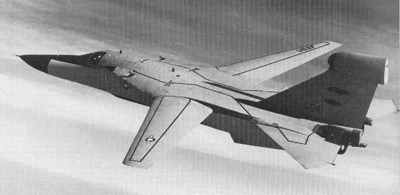
EF-111A
The EF 111A was born out of a series of studies undertaken during the late ’60s aimed at providing the USAF with a tactical EW system to replace its ageing fleet of EB 66 aircraft. The emergence of ALQ 99E tactical jamming system gave the green light for full scale airframe development and in January 1975, Grumman was awarded a $85.9 million contract for the construction of two prototype EF-111s. These aircraft were in fact preceded by an F 111A fitted with a ventral ‘canoe’ radome of the type proposed for the production models and which was used to test the aerodynamics of the installation together with five static air frames which were used in a series of electronic tests. The first fully aerodynamically representative prototype (AF serial 66 0049) made its maiden flight on 10th March, 1977 and was followed by a second aircraft (66 0041) which carried a complete electronic suite on 17 May 1977. Both aeroplanes were involved in an 84 flight company test programme and an 86 flight evaluation by the USAF. Surplus F 111A airframes were chosen for the programme and Grumman was assigned the task of converting the type into a dedicated EW platform.
In November 1979, full scale production of the EF 111A was sanctioned and the two prototypes were re worked to definitive standard. Aircraft number 049 reappeared on 19th June, 1981 and was initially retained by Grumman for further testing whilst 041 became the first ‘production’ air¬craft to be delivered to the USAF. Despite outward appearances, the EF-111A is a virtual re build of the original aircraft. During conversion, Grumman remove the wings and tail surfaces and strip the fuselage back to a basic keel structure. When the re build is complete, the original components have a fatigue life of approximately 8,000 hrs whilst the new features are rated for 10,000 hrs. The forward avionics bay remains unchanged and continues to carry the AN/APQ 160 navigation and the AN/APQ 110 terrain following radars which are standard to the F 111A. Aft of the radar boxes, a new oxygen converter has been installed along with a considerable quantity of new electronic equipment, the exact nature of which has not yet been cleared for publication. The basic geometry of the crew escape capsule is retained but the right hand side of the cockpit has been completely re built to house an electronic warfare officer (EWO) and his related controls. The pilot’s instrumentation remains essentially similar to that carried by the original aircraft but with some additions and re arrangement of individual items. The complete EF 111A cockpit layout is shown in the accompany¬ing illustration. Aft of the cockpit, the weapons bay has been extensively re worked to house the transmission and other elements of the Al Q 99. The installation takes the form of a pallet structure hung across the bay with nine transmitters attached to its underside and a range of related electronics above. What is known about the exact distribution of these items is shown in the accompanying inboard profile. Completing the weapons bay modifications is a 4.9m long canoe’ radome for the ALQ 99’s transmission antenna built into the underside of the bay doors. The electronics pallet is quoted as weighing 1,939kg with the ‘canoe’ adding a further 210kg, giving a total installation weight of 2,149kg. To provide power for the system, the original 60kVA engine mounted generators have been replaced with units rated at 90kVA. To cope with this increase, a new electrical sub system has been installed involving extensive re wiring. To cope with the heat output of the palletised ALQ 99, two new environmental control systems have been installed, namely the air cycling system from the F 111F and a refrigeration system to provide a constant 4.4 degrees C air flow for electronics cooling. The air cycling unit uses a ram air intake below the starboard main engine inlet duct and two exhausts mounted on either side of the rear of the under fuselage. The remaining modification of note concerns the vertical tail surface which has been re stressed to carry a fin top fairing and four side blisters designed to house a systems integrated receiver (SIR) group which is used to provide threat data for the various onboard EW systems. The fin top ‘pod’ is produced by Canadair and weighs, fully equipped, a respectable 432kg. An integral ‘glove’ is used to fair the installation into the vertical surface. The standard F 111A vent tank and HF antenna are retained within the fin structure. The EF-111A flew in production form on 28 June 1981. Production Ravens achieved an initial operational capability in November 1983 and entered service with a USAF unit in England in 1984. The 42nd and last was delivered in December 1985.
F-111A Engines: 2 x Pratt & Whitney TF30-P-3 turbofan 12.500/21,000 lb (5,670/9,525 kg). Wing span: 63 ft 0 in (19.20 m) fully forward, 31 ft 11.5 in (9.74 m) fully swept. Length: 73 ft 6 in (22.40 m). Height: 17 ft 1.5 in (5.22 m). Gross weight: approx 80,000 lb (36287 kg). Max speed: 1,650 mph (2,655 km/h) above 36,000 ft (11,000 m). Max range (internal fuel): 2,750 (4,425 km). Crew: 2.
EF-111A Engine: 2 x P&W TF30-P-3 turbofan, 18,500 lb thrust. Installed thrust: 164.6 kW. Wing span: 19.2-9.8 m (63-32 ft). Length: 23.16m. Height: 6.10m. Wing area: 48.8 sq.m Empty wt: 25,070 kg. MTOW: 40,340 kg. Max combat speed: 2,216 kph. Initial ROC: 5690 m / min. Service ceiling: 13,715 m. T/O run: 1350 m. Ldg run: 600 m. Fuel internal: 19,000 lt. Ferry range (on internal fuel): 3,706km. Unrefuelled endurance: 4 hr plus. Combat radius: 370-1,495km.
F-111B First fight: 18 May 1965. Wing span: 70 ft. Length: 67 ft 6 in
FB-111 Span: 72.5deg 10.34 m (33 ft 11 in); 16deg sweep 21.34 m (70 ft) Length: (with probe) 23.1 m (75 ft 9.5 in) Gross weight: (after in flight refuelling) 55747 kg (122900 lb) Maximum speed: (Sea level, clean, most versions) 1346 km/h (836 mph, Mach 1.1); (high altitude, clean) 2335 km/h (1450 mph, Mach 2.2)
FB-111A Engines: 2 x Pratt & Whitney TF30-P-7 turbofan, 20,350 lb / 9231 kg thrust. Wingspan: 70 ft 0 in / 21.34 m Wingspan swept: 33 ft 11 in / 10.34 m Length: 73 ft 6 in / 10.34 m Height: 17 ft 1.5 in / 5.22 m MTOW: 114,300 lb / 51,846 kg Speed: 1650 mph / 2655 kph Ceiling: 60,000 ft / 18,290 m Range: 2925+ mi / 4707+ km Armament: six SRAM missiles (or nuclear bombs) or up to 37,500 lb (17,010 kg) of conventional bombs. Crew: 2
F-111C Engine: Two Pratt and Whitney TF-30 turbofans (9,500 kg thrust each) 21.3m extended, 10.3m swept Sweep: 72.5-16deg Length: (with probe) 23.1 m (75 ft 9.5 in) Height: 5.3m Basic Weight: 24,000kg Gross weight: 51846 kg (114300 lb) Maximum speed: (Sea level, clean, most versions) 1346 km/h (836 mph, Mach 1.1); (high altitude, clean) 2335 km/h (1450 mph, Mach 2.2) Crew: 2
RF-111C Wing span: 19.2 m / 9.8 m (63-32 ft).
F-111D Span: 72.5deg sweep 9.74 m (31 ft 11.5 in); 16deg sweep 19.2 m (63 ft) Length: (with probe) 23.1 m (75 ft 9.5 in) Gross weight: 41958 kg (92500 lb) Maximum speed: (Sea level, clean, most versions) 1346 km/h (836 mph, Mach 1.1); (high altitude, clean) 2335 km/h (1450 mph, Mach 2.2)
F-111E Span: 72.5deg sweep 9.74 m (31 ft 11.5 in); 16deg sweep 19.2 m (63 ft) Length: (with probe) 23.1 m (75 ft 9.5 in) Gross weight: 41958 kg (92500 lb) Maximum speed: (Sea level, clean, most versions) 1346 km/h (836 mph, Mach 1.1); (high altitude, clean) 2335 km/h (1450 mph, Mach 2.2)
F-111F Span: 72.5deg sweep 9.74 m (31 ft 11.5 in); 16deg sweep 19.2 m (63 ft) Length: (with probe) 23.1 m (75 ft 9.5 in) Gross weight: 45360 kg (100000 lb) Maximum speed: (Sea level, clean, most versions) 1346 km/h (836 mph, Mach 1.1); (high altitude, clean) about Mach 2.5.
The F 16 was not originally planned as an equipment item for the inventory, but as a candidate for a Light Weight Fighter (LWF) technology demonstrator programme to examine the possibility of building a fighter significantly smaller and cheaper than the F 15. Five companies submitted proposals for an LWF on February 28, 1972, General Dynamics and Northrop were selected to build two prototypes each, designated YF 16 and YF-17, respectively, on April 13, 1972, and on January 13, 1975, the Secretary of the Air Force announced that the F 16 was the final choice. By this time, the emergence of a market, especially among a group of European NATO nations, had caused the programme rather quickly to be recast as an Air Combat Fighter (ACF), with procurement of an operational version promised by the USAF. At the same time, the original concept of a light and uncompromised close-combat dogfighter was changed to include all-weather capability in both the air to air and air to surface roles, with heavy loads of the full spectrum of tactical stores.
The first of two prototypes (72-01567) of the YF-16 (GD model 401) was airlifted from Fort Worth to Edwards AFB in January 1974 and was officially flown for the first time of the 2nd of February 1974, although this aircraft had made an unofficial and unscheduled flight on 20 January after becoming airborne in the hands of Philip Oestricher, who elected to take off when the tailplane was damaged during high-speed taxi tests. An ‘official’ first flight followed on February 2, and subsequent testing was encouraging. The chosen engine was a single Pratt & Whitney F100 PW 100 two shaft augmented turbofan, with maximum thrust rating of 10800 kg (23810 lb) with full afterburner. This engine was chosen because it was already fully developed and in production for the F 15. Although it has a modulated variable profile nozzle, it is fed from a simple fixed inlet and ventral duct to reduce complexity and cost. This reduces maximum high altitude Mach number to below 2.0, but this is considered of little consequence. Virtually all modern air combat takes place at medium to low altitudes at speeds in the order of 650 km/h (404 mph), and turn radius is far more important than speed. The F 16 pilot sits in a reclining McDonnell Douglas seat (of course, with zero/zero capability) and flies with a sidestick controller resembling a miniature control column on the right cockpit console. This small controller is easy to manage under conditions of high g acceleration, and the sloping seat also helps the pilot resist g forces. The controller hardly moves under the pilot’s input demands; instead it contains transducers which sense the pilot’s applied forces. The resulting electrical signals, and those from the rudder pedals, serve as primary inputs to a fly by wire (FBW) control system which also includes the digital autopilot, computer, weapon delivery system and power units driving the flight controls.
F-16E
The wing and fuselage are blended structurally and aerodynamically and, like the tail, incorporate major portions of graphite‑epoxy composite, glass‑fibre, titanium and other advanced materials. There are only five ribs in each wing, but no fewer than 12 spars, all linked to body frames. Long vortex extensions at the root give powerful lift at high angles of attack and allow the wing proper to be made significantly smaller. Along the top of the left extension strake is the M61 20‑mm (0.79‑in) cannon, with a 500‑round ammunition drum lying transversely in the top of the fuselage. About 3162 kg (6971 lb) of fuel is housed in various cells in the wing and fuselage which are governed as two tanks, with a flight‑refuelling receptacle in the top of the mid‑fuselage matched to the SAC Flying Boom type of refuelling method.
Moveable leading-and trailing-edge flaps, controlled automatically by the aircraft’s speed and attitude, enable the wing to assume an optimum configuration for lift under all conditions of flight. All flying controls are operated by a ‘fly-by-wire’ electronic system.
The F-16 has a single vertical tail surface, mid-set all-moving tailplane and mid-set wings of 40 degree leading-edge sweep.
The tailplane is of the taileron type, the two halves operating in unison for pitch control and differentially for roll control.
The full-span ailerons are of the flaperon type, again operating differentially for roll control and in unison for increased lift.
The leading edges are hinged to allow the automatic flight-control system to schedule them as automatic leading-edge flaps and, in concert with the ‘flaperons’, provide a measure of variable camber to the wing.
Take-off and landing has the leading edge flaps at 2 degrees and the flaperons down 20 degrees.
Initial climb has the leading-edge flaps angled down at 15 degrees and the flaperons down at 20 degrees.
High speed flight has the leading-edge flaps and the flaperons both at 2 degrees up.
For manoeuvring, the leading-edge flaps are angled down at 25 degrees and the flaperons level.
Approach has the leading-edge flaps at 15 degrees and the flaperons down at 20 degrees.
In the nose is a Westinghouse X‑band pulse‑doppler radar, with planar‑array aerial. It can function in many modes including air-to‑air look‑up or look‑down, auto‑acquisition dogfight, air‑to‑ground ranging, ground mapping, expanded mapping, doppler beam-sharpening, beacon, ‘freeze’ (fixed display), and two types of Sea Mode for anti-shipping missions. Delco make the computer, Marconi‑Elliott of Britain, the advanced HUD (head‑up display), Kaiser the head‑down display (HDD) and Singer‑Kearfott the inertial navigation system. Up to 6894 kg (15 200 lb) of weapons, ECM pods and tanks can be carried on nine pylons.
The YF-16 prototypes were being flown by six pilots, two each from General Dynamics, the Air Force Flight Test Centre and the Tactical Air Command. The single-seat, single-engine aircraft, 47 feet long with a 30-foot wingspan, is designed as a compact, low-cost fighter for air-to-air combat. It also can carry nearly 9,0001b of missiles and bombs for air-to-ground missions. The YF-16 is powered by a Pratt & Whitney F-100-PW-200 turbofan, the same engine used in the Air Force F-15 fighter. The F-100 engine produces about 25,0001b / 10814kg of thrust with full afterburner.
The F-16 is built in three major subsections. Some 80 percent of the airframe is made of conventional aluminium alloy, and about 60 percent is from sheet metal. Steel, composites and titanium represent about 8 percent of the structure. The wing is a cropped delta with a 40-degree leading-edge sweep. It has a 4 percent thickness/chord ratio and a 64A204 airfoil section. The structure consists of eleven spars and five ribs. Upper and lower skins are machined from a single piece. The wing is blended into the fuselage which creates a significant stowage area for internal fuel, which accounts for 31 percent of the loaded weight of the F-16. Leading edges are blended into the fuselage with strakes which, at high angles of attack, create vortices that maintain energy in the airflow over the wings, delaying root stalling and contributing to directional stability. Trailing edges have inboard “flappers” which combine the functions of flaps and ailerons. They can be drooped to 20 degrees. Leading-edge flaps contribute to the aircraft’s legendary manoeuvrability. The single vertical tail is of multi-rib, multi-spar construction in aluminium, with the skin made of graphite epoxy. Two ventral fins are made of glass fibre. There is an all-flying tailplane. Main and nosewheel gear retract into the fuselage. The single air intake is mounted underneath the fuselage, giving the F-16 its distinctive profile. This location was chosen to provide minimal airflow disturbance over a wide range of aircraft attitudes. Location of the nosewheel gear aft of the intake means that FOD (foreign object damage) ingestion problems have been minor. The intake is of fixed geometry. A separation strut provides additional tunnel ridigity. Many parts are interchangeable between port and starboard including the horizontal tail surfaces, flaperons and most of the main landing gear. The view from the cockpit is exemplary. A polycarbonate clamshell canopy encloses the pilot who sits on an ACES II rocket powered ejection seat, cleared for ‘zero-zero’ performance up to 600 knots and/or 50,000 ft. The inside of the canopy is tinted with a thin gold film, which dissipates radar energy. The seat is raked backwards at 30 degrees, to enhance the pilot’s ability to withstand high g. Instead of a conventional control column, the F16 is fitted with a sidestick controller mounted to starboard. “Fly-by-wire” powered controls and artificial “feel” require the sidestick to be moved only millimetres.
In April 1975, the first definitive USAF contract specified six F‑16As and two tandem‑seat dual‑control F‑16B trainers with full combat capability (the B has 17% less internal fuel). The USAF said it would buy 650 aircraft in all, but this total was subsequently been increased to a currently planned force of 1388 aircraft. On June 7, 1975, at the Paris air show, it was jointly announced by Belgium, Denmark, the Netherlands and Norway that they had selected the F‑16 over two other candidate aircraft to replace the F‑104, buying initial totals of: Belgium 90A+ 12B+ 14 options; Denmark 40A+8B+ 10 options; the Netherlands 84 (A, B combined)+ 18 options; and Norway 60A+ 12B (no options).
In September 1976, Iran ordered 160 from the US Government, signifying its eventual requirement for a total of 300. Iran is unlikely to participate in manufacture, but the four European countries signed a complex collaborative/offset deal which gives them the right to make major parts of the airframe, engine and equipment, both for their own purchases and those of other customers including the USAF. Since 1976, Turkey has expressed a wish to join this consortium, but no decision had been announced by them by early 1978.
F-16XL
The first production F 16A (75 0745) flew on 8 December 1976 at Fort Worth, Texas, and the first F 16B on August 8, 1977. The first operational F-16A was delivered in January 1979 to the 388th Tactical Fighter Wing at Hill Air Force Base, Utah and its first overseas unit, the 8th TFW at Kunsan AB, South Korea, on 1 November 1980. The first USAF unit in Europe to re-equip with Fighting Falcons was the 50th TFW at Hahn AB, West Germany on 1 December 1981. As part of a major policy decision to upgrade the equipment operated by second-line units, the F-16 has already reached the South Carolina Air National Guard, deliveries beginning in mid-1983, followed by other ANG units, as the aircraft were replaced in USAF by later models. Initial USAF production versions were the F-16A single-seater and F-16B two-seat operational trainer with an extended canopy and dual controls, powered by Pratt & Whitney F100 engines and equipped with APG-66 radars. Four European countries selected the F-16A/B, with manufacture by a consortium with two final assembly lines, in Belgium and The Netherlands.
First F-16 assembled in Europe – Belgium Air Force F-16B FB-01 first flying December 1978
The European F-16A/B aircraft have been upgraded under the Mid-Life Update program and designated F-16AM/BM.
The F-16C and F-16D aircraft, which are the single- and two-place counterparts to the F-16A/B, incorporate modern cockpit control and display technology. The F-16C/D models were the result of a multi¬national staged improvement programme (MSIP) initiated in 1980. Changes include the introduction of a more capable APG-68 radar with increased detection range and track-while-scan mode, plus new cockpit displays with multifunction CRTs and a wide-angle headup display and an increase in the maximum take-off gross weight. First flown in December 1982, the F-16C/D became the standard production model, although the earlier F-16A/B was still available for export. Following General Elec-tric’s success in the Alternate Fighter Engine competition, F-16C/Ds delivered from FY1985 have comprised mixed batches of General Elec¬tric F110 and Pratt & Whitney F100-220 powered aircraft. Engine contracts are to be agreed annually, with the lowest bidder supplying the majority of the power plants for that year. In FY1985 General Electric provided 75 per cent of the engines needed for F-16C/D production. Export aircraft are available with either engine. The TUSAS organisation in Turkey is to build F-16C/D aircraft and F110 engines for the Turkish Air Force, which is purchasing 160 aircraft, including an initial batch supplied by General Dynamics. Deliveries of TUSAS assembled F-16s is scheduled to begin in 1988. The F-16CJ is a modified F-16C for the SEAD role. By June 1987 2,975 F-16s of all versions had been ordered, including aircraft for licence production (Turkey – 278, South Korea – 108, Belgium – 222, Netherlands – 300), and 1,774 had been delivered. Early in 1987 Bahrain became the 16th nation to order the F-l6, contracting for 12 aircraft powered by General Electric F110 engines. The Block 60 F-16E single and F-16F two-seat fighters feature technology improving the combat effectiveness and multi-role capability of the aircraft. Deliveries of these variants started to the United Arab Emirates as the first customer. The first Block 60 made its maiden flight in December 2003. Israel took delivery of the F-16I, which is a customized version of the F-16E/F with Israeli avionics and weapons. The F-16R is a reconnaissance version with an underfuselage pod, and the F-16N is an ‘Aggressor’ version for the US Navy. General Dynamics has elected to improve the overall performance of the F 16 in the ground attack role by installing a new cranked arrow wing. With 120 per cent more wing area and two fuselage plugs lengthening the fuselage 54 ft 1.86 in (16.51 m) to accommodate the longer root chord, the double delta F 16XL carries 82 per cent more internal fuel. Stores are carried tangentially to the wing undersurface on 17 hardpoints, and drag fully loaded is some 60 per cent less than with conventional carriage. Radar cross section is also halved. The reduction in drag and the greater fuel capacity has a dramatic effect on the F 16XL’s payload/range performance, enabling the aircraft to carry twice the payload of an F 16A to a 45 per cent greater combat radius. Penetration speeds are increased by up to 100kt to around Mach 0. 9. Air to air performance is also improved, with the 9g manoeuvre envelope doubling in size. Manoeuvre capability fully loaded is also improved from 5.5g to 7.33g. Instantaneous turn rate is increased. The variant first flew on 3 July 1982. The Air Force’s evaluation involved four F 15s and two F 16XLs. Boeing, Rockwell and McDonnell Douglas co operated with NASA to set up a series of supersonic laminar flow tests involving a single seat F 16XL in flights beginning in 1991. When these showed promise, a two seat XL was used for the second series of fights during which more than 40 flights were completed by late 1996. Research results indicate it is possible to make a 4% weight saving by applying a laminar flow wing to supersonic airliners. Of the two F 16XLs built by GD as a private venture, one is a single seater powered by a Pratt & Whitney F100 and the other is a two seater powered by the General Electric F110.
The F-16XL has a 56in / 1.42m longer fuselage boosting fuel capacity by 80%. The F-16XL has a maximum of 29 hardpoints available on 17 stores stations. The stores stations are semi-conformal to minimise drag, which is 58% less than that of the F-16, enabling the F-16XL to carry twice the payload 45% further than the basic F-16.
During the 1970s and early 1980s considerable research was undertaken into a host of aeronautical fields but this was generally performed with conversions of existing aircraft such as the F-16 Fighting Falcon converted by General Dynamics into the F-16/AFTI for investigation of direct-force controls within the overall context of the CCV (Control-Configured Vehicle) portion of the Advanced Fighter Technology Integration programme, which was intended to create a quantum leap in fighter manoeuvrability.
The very first YF-16 (72-1567) was rebuilt in December 1975 to become the USAF Flight Dynamics Laboratory’s Control-Configured Vehicle (CCV). Fly-by-wire flight controls and relaxed static stability found on all Vipers made the YF-16 an ideal candidate to evaluate control of an aircraft beyond conventional means, with independent or ‘decoupled’ flight surfaces. The YF-16/CCV could rise or fall using direct lift, move laterally by direct side force, or yaw, pitch, or roll regardless of the direction of flight. Twin vertical canards beneath the air intake and flight controls permitted use of wing trailing edge flaperons in combination with the all-moving stabilator. The YF-16/CCV flew on 16 March 1976, piloted by David J. Thigpen. On 24 June 1976, the ship was seriously damaged in a landing after its engine failed on approach. The flight test programme was resumed and lasted until 31 July 1977, when 87 sorties and 125 air hours had been logged.
Early in the development stage, General Dynamics wanted to market a simpler version of the F-16 for export, and teamed up with General Electric to create a version powered by the 8165kg thrust General Electric J79-GE-17X single-shaft turbojet, a development of the engine employed on the F-104 Starfighter and F-4 Phantom. As the J79-GE-119, this engine was installed on a full-scale development F-16B (75-0752) bailed back from the USAF. The Turbojet required a lower airflow than the P&W FI00-PW-200 used on all production F-16A/Bs so the shape of the air intake was altered. Since the J79 engine was 18 in (46 cm) longer than the F100, the rear fuselage was extended aft of the stabilator pivot point by that amount. The resulting F-16/79, made its first flight on 29 October 1980, and was existant in F-16/79A (single-seat) and F-16/79B (two-seat) versions.
The F-16/101 was a similarly re-engined example powered by a General Electric YJ101 two-shaft augmented turbojet engine delivering about 15,000 lb (6803 kg) thrust, had performed well on the Northrop YF- 17 and its builder wanted to demonstrate the much improved DFE (derivative fighter engine) version, capable of up to 26,500-lb (12,020-kg) thrust on a single-engine F-16. The retrofit was made on this first full scale development F-16A (75-0745) which flew with the GE engine on 19 December 1980. The F-16/101 made 58 test flights and logged 75 air hours before the programme ended in July 1981. The F-16/101 was not adopted but the way had been paved for development of an improved GE engine, the F 110, on the Fighting Falcon beginning with F-16C block 30/32 aircraft.
In June, 1975, four European countries (Belgium, Netherlands, Derunark, and Norway) announced plans to purchase 348 fighters. In February 1978, the first European F-16 assembly line opened at Sabca/Sonaca where Belgium took delivery on 29 January 1979 of the first locally-manufactured F-16 out of the country’s original order for 116 aircraft (96 F-16As and 20 F-16Bs). Belgian F-16As were serialed FA-01/136 (78-116/161; 80-3538/3546; 80-3547/3587; 86-0073/0077; 87-0046/0056; 88-0038/0047; 89-000110011; 90-0025/0027). F-16Bs were serialed FB-01/24 (78-0162/0173; 80-3588/3595; 87-0001; 88-0048/0049; 89-0012). FA-01/55 and FB-01/12 were upgraded to F-16A/B block 10 standard, while FA-56/136 and FB-25/24 were built as F-16A block 1s (big tail) aircraft.
Norway acquired seventy-two F-16A and B model Lawn Darts (sixty F-16As and twelve F-16Bs) from the Netherlands’ Fokker production line between 15 January 1980 and 4 June 1984. Six F-16A/B block 15 (four F-16A and two F-16B) attrition replacements were later ordered. Norway employs the F-16 in a defensive role, Scandinavian geography dictating an important anti-shipping mission. On 12 December 1979, the first Fighting Falcon for the RNAF completed its maiden flight from Fokker’s Schipol plant. Norwegian aircraft have drag chutes to operate on snowy and an identification spotlight for use during long dark winters.
In April 1978, the second European F-16 assembly line (after Belgium) opened at Fokker-VFW in the Netherlands. In May 1979, the first Dutch-assembled F-16 made its maiden flight. Holland later increased its F-16 purchase from 102 to 213 aircraft.
The USAF continues large-scale procure¬ment of F-16s, with the 180 approved in FY1986 taking total purchases to 1,859. In October 1986 the F-16 won the Air Defence Fighter (ADF) competition, a modified version of the F-16A being selected instead of the Northrop F-20A Tigershark. The ADF contract will cover the modification of existing F-l6As, and will not be for new-build aircraft. In April 1987 the US Navy took delivery of the first F-16N supersonic adversary aircraft of the 26 ordered. By 1994, production of the F-16 had been taken over by Lockheed Martin.
The F-16 Block 70 variant, also known as the F-16V, features cutting-edge enhancements including the AN/APG-83 AESA radar, new mission computers, a digital cockpit, and advanced electronic warfare systems. These upgrades provide superior situational awareness, survivability, and multirole performance.
On 18 March 2005, Lockheed Martin Aero plant in Fort Worth, Texas, delivered the final F-16 Fighting Falcon for the US Air Force; F-16CJ 01-7053. Lockheed Martin continues to produce the F-16 fighter for international customers. A total of 2231 F-16s have been produced for the U.S. Air Force.
F-16A Engine: P&W F100-220, Normal-12,420 lb st, military-14,670 lb st, afterburn-23,830 lb st. Length: 47.638 ft / 14.52 m Height: 16.699 ft / 5.09 m Wingspan: 31.004 ft / 9.45 m Wing area: 300 sq ft (27,9 sq.m). Max take off weight : 35390.3 lb / 16050.0 kg Empty wt: 15,137 lb (6 865 kg). Internal fuel: 6,972 lb (3 162 kg). Max. weight carried : 19800.9 lb / 8980.0 kg Air superiority gross weight: 23,357 lb (10952 kg) with ammunition and two Sidewinders. Wing loading: 78 lb/sq ft (397 kg/ sq.m). Thrust/weight ratio: 1.02. Max. speed : 1158 kts / 2145 km/h Cruising speed : 533 kts / 988 km/h Initial climb rate : 41338.58 ft/min / 210.0 m/s Service ceiling : 50000 ft / 15240 m Range : 1042 nm / 1930 km Fuel fraction: 30%. Armament : 1x MK 20mm M61A1, 5440kg ext 9pt. / 2-6 AIM-9 Sidewinder Seats: 1.
F 16B Engine: P&W F100-220, Normal-12,420 lb st, military-14,670 lb st, afterburn-23,830 lb st. Wingspan: 10m. Length: 15.03m. Height: 5.09m. Wing area: 27.9sq.m. Empty wt: 7909 kg. Internal fuel: 2745 kg. MTOW: 16,057 kg. Seats: 2
F-16C Engine: General Elec¬tric F110 Seats: 1
F-16C Engine: Pratt & Whitney F100-200 turbofan, 23,840 lb Wingspan: 31 ft / 9.45 m Length: 49 ft 6 in / 15.09 m MTOW: 35,400 lb / 16,057 kg Max speed: 1350 mph / 2173 kph Max ferry range: 2415 sm / 3890 km Armament: 1 x 20 mm cannon (515 rds) External load: up to 20,450 lb / 9276 kg
F-16C Fighting Falcon Engine: 1 x Pratt & Whitney F100-220 or General Electric F110-GE-100 Installed thrust (dry – reheat): 67 – 113 kN. / 27,600 – 23,450 lb / 12,519 – 10,637 kg Span: 10 m / 32 ft 9.75 in Length: 15.1 m / 49 ft 4 in Wing area: 27.87 sq.m / 300.0 sq.ft Height: 16 ft 8.5 in / 4.09 m Empty wt: 8315 kg / 18,335 lb MTOW: 19,187 kg / 42,300 lb Warload: 5413 kg. Max speed: 1320+ mph / 2124+ kph / M2+ at 40,000ft/12,190m Initial ROC: 50,000+ fpm / 15,240+ m/s Ceiling: 18,000+ m. TO run: 760 m. Ldg run: 760 m. Combat radius: 925+ km / 575+ mi Fuel internal: 4060 lt. Air refuel: Yes. Armament: 1 x 20 mm, 2/4/6 x AAM Hard points: 5 + 2 wing tips. Disposable stores: 20,450 lb / 9276 kg Seats: 1.
F-16CJ Engine: Pratt & Whitney F100, or General Elec¬tric F110 or Pratt & Whitney F100-220 Seats: 1
F-16D Engine: Pratt & Whitney F100, or General Elec¬tric F110 or Pratt & Whitney F100-220 Seats: 2
F-16E Engine: 1 x General Electric F110, 7700/13150kg Max take-off weight: 21770 kg / 47995 lb Wingspan: 10.4 m / 34 ft 1 in Length: 16.5 m / 54 ft 2 in Wing area: 62 sq.m / 667.36 sq ft Max. speed: 2200 km/h / 1367 mph Crew: 1
F 16XL Engine: General Electric F110 Length: 54 ft 1.86 in (16.51 m) Hardpoints: 17 Penetration speed: Mach 0. 9. Manoeuvre capability: 7.33g. Seats: 2
F 16XL Engine: Pratt & Whitney F100 Length: 54 ft 1.86 in (16.51 m) Hardpoints: 17 Penetration speed: Mach 0. 9. Manoeuvre capability: 7.33g. Seat: 1
F-16/79 Engine: General Electric J79-GE-119
F-16/101 Engine: General Electric YJ101, 26,500-lb (12,020-kg)
Engine: 1 x P+W F-100-PW-100, 112.1kN Max take-off weight: 9780-15000 kg / 21561 – 33070 lb Empty weight: 6330 kg / 13955 lb Wingspan: 9.3 m / 30 ft 6 in Length: 14.4 m / 47 ft 3 in Height: 5.0 m / 16 ft 5 in Wing area: 26.0 sq.m / 279.86 sq ft Max. speed: M1.2 Ceiling: 19000 m / 62350 ft Range w/max.fuel: 3200 km / 1988 miles Range w/max.payload: 500 km / 311 miles Armament: 1 x 20mm machine-guns, 5000kg of bombs or missiles Crew: 1
Engine: one 129 kN (26,000 lb st) General Electric F110-GE-129 or Pratt & Whitney F100-P-229 turbofan Length 15.03m (49 ft 4 in) Height 5.09m (16 ft 8.5 in) Wing span (over tip launchers) 9.45m (31ft 0 in) Take-off weight (clean): 9.791 kg (21,585 lb) Max Take-Off Weight: 19.187 kg (42,300 lb) Armament: one 20mm M61A1 Vulcan six-barrel gun 515 rounds; 9276 kg (20,450 lb) of disposable stores Hardpoints: nine
The Learjet 60 was announced in October 1990 as the replacement for the Model 55C, from which it is derived. A proof of concept airframe flew for the first time on 18 October 1990 powered by one Garrett TFE331-3A and one PW305 engine. The first twin-PW305-powered Learjet 60 made its first flight from Mid-Continent Airport, Wichita, on 13 June 1991, and certification and early deliveries are targetted for the end of 1992. The Model 60 is the largest of the Learjet family and incorporates new fuel-efficient engines, a fuselage 0.07m wider and stretched by 1.43m, a ‘glass cockpit’, ‘steer by wire’ nosewheel, and an optional higher MTOW of 10478kg. Thrust reversers and single-point refuelling are also standard equipment, and the aircraft features a full galley, together with an aft toilet. By mid-1991, Learjet claimed to have sold the first full year’s production to customers in seven countries.
Engines: 2 x Pratt & Whitney Canada PW305 turbofans, 1995kg Take-off weight: 10319 kg / 22750 lb Wingspan: 13.34 m / 43 ft 9 in Length: 17.88 m / 58 ft 8 in Height: 4.47 m / 14 ft 8 in Wing area: 24.57 sq.m / 264.47 sq ft Max. speed: 858 km/h / 533 mph Ceiling: 15545 m / 51000 ft Range: 4441 km / 2760 miles
Learjet’s Longhorn series combines a revolutionary wing design, two of the most advanced engines introduced to the market, and 51,000-foot performance. The line of five aircraft has been designated the Learjet 28 and Learjet 29, both powered by General Electric turbojets, and the Learjet 54/55/56, and those three are powered by twin Garrett AiResearch fanjets. All the models are designed with a larger wing incorporating near-vertical winglets that have replaced the traditional Learjet tiptanks. The wing’s increased aspect ratio and super-critical winglets provide substantial aerodynamic improvements that in turn produce greater fuel efficiency and improved flight performance at high and low altitudes. The wing also has been responsible for significantly improved short-field performance. The balanced field length is 3,520 feet for the 54/55/56 series.
Engines two 3,650-lb. s.t. Garrett AiResearch fanjets. Gross wt. 20,000 lb Empty wt. 10,257 lb Fuel capacity 1,194 USG. Top speed 550 mph. Stall 100 mph. Initial climb rate 4,700 fpm. Ceiling 51,000 ft. Range 3, nm. Balanced field length 4,160 ft. Seats 12
At the 1977 Paris air show Gates Learjet announced details of its new Learjet 50 series. This was intended to comprise the Learjet 54, Learjet 55 and Learjet 56 with longer and larger cabins, all powered by twin Garrett AiResearch fanjets. The 55 was to have advanced wings incorporating NASA-developed winglets and this last feature gave rise to the name Longhorn. The larger wing incorporating near-vertical winglets that have replaced the traditional Learjet tiptanks. The wing’s increased aspect ratio and super-critical winglets provide substantial aerodynamic improvements that in turn produce greater fuel efficiency and improved flight performance at high and low altitudes. The wing also has been responsible for significantly improved short-field performance. The balanced field length is 3,520 feet for the 54/55/56 series. Only the Longhorn 55 has been developed, construction of the first airframe starting in April 1978 after successful testing of an aerodynamic prototype of the wing on a Learjet 25. The first of two Learjet 55 prototypes was flown initially on 19 April, 1979, and certification and delivery of the first production aircraft were recorded on 18 March 1981 and 30 April 1981 respectively. The Model 55 followed the same overall configuration as earlier members of the Learjet family, and accommodated a crew of two on a separate flight deck and up to 10 passengers in the main cabin. In September 1986 the company announced the Model 55B, offering a new interior, ‘glass’ cockpit, improved take-off performance and increased range, all of which increased the aircraft’s operational flexibility. One year later, the Model 55C was revealed, fitted with rear underfuselage ‘Delta Fins’ giving improved directional stability at all speeds and reducing the landing speed, and thus removed the need for a stick puller/pusher. Launched in 1987 was the Model 55C, which has a longer fuselage and deeper cabin than the 31. The engines were more powerful 3,700 lb st (16,46 kN) units and winglets and Delta-Fins were also standard. Later versions are the 55C/ER extended-range version fitted with an extra tank holding 1175kg of fuel in the tailcone, and the Model 55C/LR giving even-longer-range through the installation of a further 322-litre fuel cell behind the standard fuselage tank. Typical configuration of this version is two crew and seven passengers. Around 150 Model 55 variants had been built by the end of 1990 and the version is to be superseded by the Learjet 60 during 1992.
LR-55 Learjet Longhorn 55 Engines: 2 x Garrett TFE 731-3A-2B, 3700 lbs thrust. Seats: 12. Length: 55.1 ft. Height: 14.7 ft. Wingspan: 43.8 ft. Wing area: 265 sq.ft. Wing aspect ratio: 7.2. Maximum ramp weight: 20,750 lbs. Maximum takeoff weight: 20,500 lbs. Standard empty weight: 12,530 lbs. Maximum useful load: 8220 lbs. Zero-fuel weight: 15,000 lbs. Maximum landing weight: 17,000 lbs. Wing loading: 73.7 lbs/sq.ft. Power loading: 2.6 lbs/lb. Maximum usable fuel: 6682 lbs. Best rate of climb: 4380 fpm. Certificated ceiling: 51,000 ft. Max pressurisation differential: 9.4 psi. 8000 ft cabin alt @: 51,000 ft. Maximum single-engine rate of climb: 1250 fpm @ 200 kts. Single-engine climb gradient: 379 ft/nm. Maximum speed: 483 kts. Normal cruise @ 41,000ft: 456 kts. Fuel flow @ normal cruise: 1014 pph. Stalling speed gear/flaps down: 103 kts. Balanced field length 3,900 ft
Learjet 55C Engines: 2 x Garrett TFE731-3A-2B turbofans, 1678kg Max take-off weight: 9525 kg / 20999 lb Empty weight: 5832 kg / 12857 lb Wingspan: 13.35 m / 43 ft 10 in Length: 16.80 m / 55 ft 1 in Height: 4.48 m / 14 ft 8 in Wing area: 24.57 sq.m / 264.47 sq ft Max. speed: 884 km/h / 549 mph Cruise speed: 744 km/h / 462 mph Ceiling: 15545 m / 51000 ft