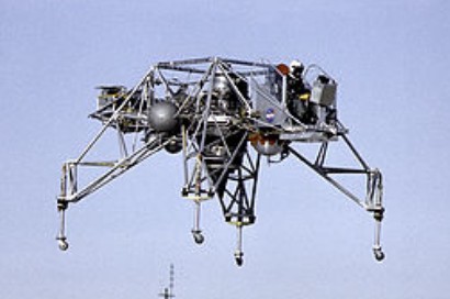
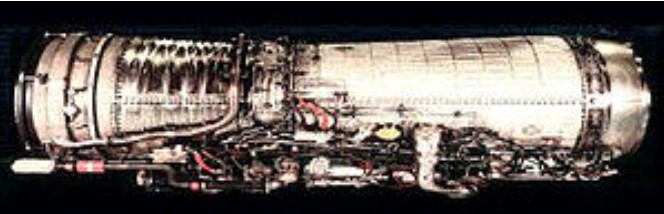
Lunar Landing Research Vehicle (LLRV) with its CF700 in the center of the vehicle
The General Electric CF700 (military designation TF37) is a turbofan development of the CJ610. The CF700 has an uncommon rear-mounted fan connected directly to the low-pressure turbine blade for improved fuel economy.
Applications: Dassault Falcon 20 North American Sabreliner Series 75A and 80 Lunar Landing Research Vehicle/Lunar Landing Training Vehicle
Specifications:
CF700 Type: Single spool turbofan Length: 75.5 in (1,918 mm) Diameter: 33 in (838 mm)) Dry weight: 735 lb (333.4 kg) with optional thrust reverser Compressor: 8 stage high pressure compressor + 1 stage fan directly driven by the free LP turbine Turbine: 2 stage high pressure turbine, 1 stage low pressure turbine Fuel type: Aviation kerosene Maximum thrust: 4,200 lbf (18.68 kN) Bypass ratio: 2.0:1 Specific fuel consumption: 0.67 lb/lbf-hr (68.3 kg/kN-hr) at maximum cruising speed Thrust-to-weight ratio: 6.6:1
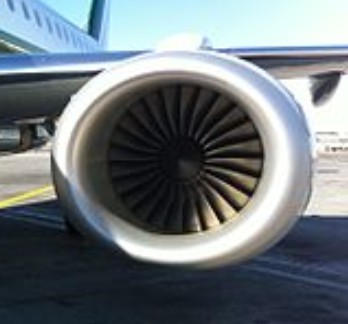
The General Electric CF34 is a civilian turbofan developed by GE Aircraft Engines from its TF34 military engine. First run in the 1960s, the original engines comprise a single stage fan, driven by a 4-stage LP turbine, supercharging a 14-stage HP compressor, driven by a 2-stage HP turbine, with an annular combustor. Later higher thrust versions of the CF34 feature an advanced technology core, with only 10 HP compressor stages. Later variants, the -10A and -10E, were derived from the CFM56 engine family, and have a radically different HP spool, comprising a 9 stage compressor driven by a single stage turbine. The LP spool has 3 core booster stages behind the fan. Static thrust is 18,500 lbf for the -10E variant.
CF34-3 Length: 103 in (2.6 m) Diameter: 49 in (1.2 m) Dry weight: 1,625 lb (737 kg) – 1,670 lb (760 kg) Compressor: 1 fan / 14 HP stages Turbine: 4 LP stages / 2 HP stages Thrust at sea level: 9,220 lbf (41.0 kN) Power-to-weight ratio: 5.6:1 Overall pressure ratio at max. power: 21:1 Bypass ratio: 6.2:1
CF34-8 Length: 121.2 in (3.08 m) – 128 in (3.3 m) Diameter: 52 in (1.3 m) – 53.4 in (1.36 m) Dry weight: 2,408 lb (1,092 kg) – 2,600 lb (1,200 kg) Compressor: 1 fan / 10 HP stages Turbine: 4 LP stages / 2 HP stages Thrust at sea level: 13,790 lbf (61.3 kN) – 14,510 lbf (64.5 kN) Power-to-weight ratio: 5.3:1 Overall pressure ratio at max. power: 28:1 – 28.5:1 Bypass ratio: 5:1
CF34-10 Length: 90 in (2.3 m) – 145.5 in (3.70 m) Diameter: 57 in (1.4 m) Dry weight: 3,700 lb (1,700 kg) Compressor: 1 fan + 3 LP stages / 9 HP stages Turbine: 4 LP stages / 1 HP stage Thrust at sea level: 18,285 lbf (81.34 kN) – 20,000 lbf (89 kN) Power-to-weight ratio: 5.2:1 Overall pressure ratio at max. power: 29:1 Bypass ratio: 5:1
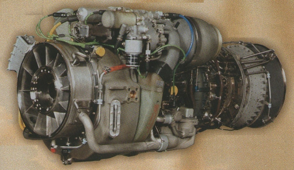
The General Electric T700 and CT7 are a family of turboshaft and turboprop engines in the 1,500-3,000 shp class.
In 1967, General Electric began work on a new turboshaft engine demonstrator designated the “GE12” in response to US Army interest in a next-generation utility helicopter. The Army effort led, in the 1970s, to development of the Sikorsky S-70 Black Hawk, powered by twin GE “T700” turboshafts, the production descendant of the GE12.
The T700 was initially bench-tested in 1973, passed military qualification in 1976, and went into production in 1978. The initial “T700-GE-700” is an ungeared free-turbine turboshaft, with a five-stage axial / one-stage centrifugal mixed-flow compressor, featuring one-piece “blisk” axial stages, with the inlet guide vanes and first two stator stages variable; an annular combustion chamber with central fuel injection to improve combustion and reduce smoke; a two-stage compressor turbine; and a two-stage free power turbine with tip-shrouded blades. The engine is designed for high reliability, featuring an inlet particle separator designed to spin out dirt, sand, and dust. The T700-GE-700 is rated at 1,622 shp (1,210 kW) intermediate power.
The T700-GE-700 was followed by improved and uprated Army engine variants for the UH-60 Black Hawk and the AH-64 Apache helicopters, as well as marinized naval engine variants for the SH-60 Seahawk derivative of the Black Hawk, the SH-2G Seasprite, and the Bell AH-1W Supercobra. T700s are also used on Italian and commercial variants of the AgustaWestland EH101/AW101 helicopter, and Italian variants of the NHIndustries NH90 helicopter. These are all twin-engine machines, except for the three-engined EH101.
The commercial version of the T700 is the “CT7”, with the engine used on the Bell 214ST (an enlarged version of the Huey), commercial Black Hawks, and the Sikorsky S-92 derivative of the Black Hawk, all of which are twin-engine helicopters.
The CT7 turboprop variants use the same core as the turboshaft variants, with a propeller gearbox fitted forward of the core. CT7 turboprops are used on variants of the Swedish SAAB 340 airliner, the Indonesian-Spanish Airtech CN-235 cargolifter, and the Czech Let L-610G airliner, all twin-turboprop aircraft. The baseline CT7-5A provides 1,735 shp (1,294 kW) on takeoff.
In the late 1980s, GE also proposed a much larger turboprop, the T407/GLC38, with a five-stage axial/one-stage centrifugal mixed-flow compressor; an annular combustor with 15 burners; a two-stage compressor turbine; a three-stage power turbine; and max takeoff power of 6,000 shp (4,475 kW). The YT706 is based on the CT7-8A engine. Compared with the T700 powering H-60 helicopters, the YT706 has a larger compressor, hot section improvements and a full authority digital engine control. The YT706 provides up to 30 percent more power than the current T700-701C and will increase the hot-and-high mission capability of the MH-60M Black Hawk procured by the U.S. Army for its Special Operations applications.
Variants:
T700: Military turboshaft engine. YT700: Prototype version. T700-700: Initial T700 variant. The improved T700-GE-701A, -701B, -701C,-701D versions have also been developed fro the original -700. T700-TEI701D: Licensed produced version of Tusaş Engine Industries of Turkey. Developed for use in the Sikorsky/Turkish Aerospace Industries T-70 Utility Helicopter.
CT7 turboshaft: Commercial version of T700. CT7-2A : Basic model CT7-2D : Higher flow compressor and surface coatings to improve resistance to wear and corrosion CT7-2D1 : Similar to the CT7-2D but uses a CT7-6 type hot section CT7-6 CT7-6A CT7-8 CT7-8A CT7-8A1 CT7-8A5 CT7-8B CT7-8B5 CT7-8E CT7-8E5 CT7-8F CT7-8F5
CT7 turbprop: Turboprop version of CT7. CT7-5A2 CT7-5A3 CT7-7A CT7-7A1 CT7-9B CT7-9B1 CT7-9B2 CT7-9C CT7-9C3 CT7-9D CT7-9D2
Applications:
T700/CT7 turboshaft AgustaWestland AW101 AgustaWestland AW149 AgustaWestland AW189 AgustaWestland CH-149 Cormorant Bell 214ST Bell 525 Bell AH-1W SuperCobra Bell AH-1Z Viper Bell UH-1Y Venom Boeing AH-64 Apache Kaman SH-2G Super Seasprite Lockheed Martin VH-71 Kestrel Mitsubishi H-60 NHIndustries NH90 Piasecki X-49 Sikorsky CH-148 Cyclone Sikorsky HH-60 Jayhawk Sikorsky HH-60 Pave Hawk Sikorsky SH-60 Seahawk Sikorsky UH-60 Black Hawk Sikorsky S-70 Sikorsky S-92 Sikorsky S-97
CT7 turboprop CASA/IPTN CN-235 Let L-610G Saab 340 Sukhoi Su-80
Specifications:
T700 Type: Turboshaft Length: 47 in (T700-GE-700/701 series) to 48.2 in (T700/T6A) Diameter: 25 in / 26 in (T700/T6E) Dry weight: 400 lb (YT700-GE-700); 437 lb (T700-GE-700); 537 lb (T700/T6E) Compressor: 6 stage-5 stage axial, 1 stage centrifugal. Combustors: Annular Turbine: 2 stage gas generator and 2 stage power turbine Fuel type: JP-4 or JP-5 (YT700-GE-700) Oil system: self contained, pressurized, recirculating dry sump Maximum power output: YT700-GE-700:1,536 shp (1,145 kW); T700-GE-700: 1,622 shp (1,210 kW); T700/T6E: 2,380 shp (1,775 kW); YT706-GE-700: 2,638 shp (1,967 kW) Overall pressure ratio: 17x Specific fuel consumption: 0.433 (T700/T6E) to 0.465 (T700-GE-701A) Power-to-weight ratio: 3.84 shp/lb (YT700-GE-700); 3.71 shp/lb (T700-GE-700); 4.48 shp/lb (T700/T6E)
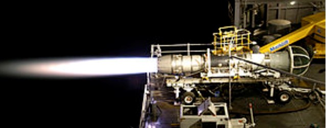
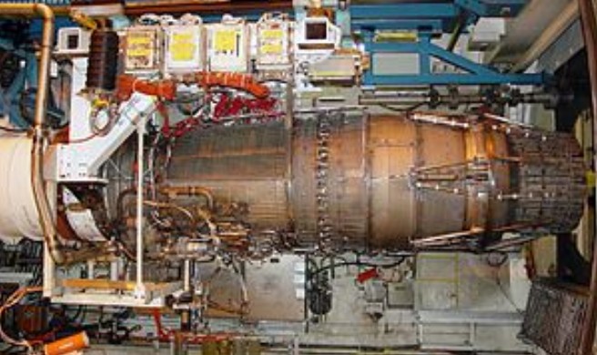
General Electric began developing the YF120 for the ATF competition in the early 1980s. Unlike competitor Pratt & Whitney, GE elected against developing a conventional low bypass turbofan and instead chose to design a variable cycle engine. This decision was made as a result of the challenging ATF requirement of supercruise. This meant the engine had to produce a large amount of dry thrust (without afterburner) and therefore have high off-design efficiency (“design” being standard cruise conditions).
The core technology used in the YF120 was developed during two industry-government programs, the Advanced Technology Engine Gas Generator (ATEGG) and Joint Technology Demonstration Engine (JTDE) programs.
The YF120’s variable cycle system worked by varying the bypass ratio of engine for different flight regimes, allowing the engine act like either a low bypass turbofan or nearly a turbojet. As a low bypass turbofan, the engine performed similar to comparable engines. When needed, however, the engine could direct more airflow through the hot core of the engine (like a turbojet), increasing the specific thrust of the engine. This made the engine more efficient at high altitude, high thrust levels than a traditional low bypass turbofan.
An expected disadvantage of this variable cycle system would be increased complexity and weight. GE claims to have combated this by using simple pressure driven valves rather than complex mechanically actuated valves to divert airflow. GE stated that this system resulted in the variable cycle system adding only 10 lb to the engine. Additionally a production F120 engine was expected to have 40% fewer parts than the F110 engine.
The YF120 engine featured a two-dimensional thrust vectoring nozzle. The nozzle allowed for vectoring in the pitch direction. This capability gave the aircraft it was installed in a serious advantage in pitch agility by greatly increasing the amount of nose pitching moment available to the aircraft. The pitching moment is traditionally generated by the horizontal stabilizer (and/or canard, if applicable), but with a thrust vectoring nozzle that moment can be agumented by the thrust of the engine. Furthermore, the pitching moment can be maintained even at low airspeed when the reduced dynamic pressure on the control surfaces makes them relatively ineffective.
GE lost the engine competition for this aircraft to Pratt & Whitney F119. While the YF120 engine never went into production, it was installed in the YF-22 used for the high angle of attack demonstration program as part of the ATF competition. During this demonstration, the YF120 powered aircraft flew, trimmed, at 60 degrees angle of attack at 82 knots. At this attitude the aircraft was able to demonstrate controlibility. Later analysis revealed that the aircraft could have maintained controlled, trimmed flight up to 70 degrees angle of attack.
The YF120 was also proposed as the basis for a more exotic engine, the Turbine-Based Combined Cycle (TBCC) engine that was to be used in demonstrator aircraft like the X-43B and future hypersonic aircraft. Specifically, the YF120 was to be the basis for the Revolutionary Turbine Accelerator (RTA-1). The variable cycle technology used in the YF120 would be extended to not only turn the engine into a turbojet but also into a ramjet. In that mode all airflow would bypass the core and be diverted into the afterburner-like “hyperburner” where it would be combusted like a ramjet. This proposed engine was to accelerate from 0 to Mach 4.1 (at 56,000 ft) in eight minutes.
Applications: Lockheed YF-22 Northrop YF-23
Specifications:
YF120 Type: Twin-Spool, Augmented Turbofan Length: 4,242 mm Diameter: 1,067 mm Dry weight: 1,860 kg Compressor: Two stage fan, five stage high pressure compressor (estimated) Combustors: Annular Combustor Turbine: Single stage HPT, Counter-Rotating Single Stage LPT Nozzle: Two Dimensional Vectoring Convergent/Divergent Fuel type: JP-4 or JP-8 Maximum thrust: 35,000 lbf (160 kN) – class
First run on 20 May 1993, GE evolved the F404 into the F412-GE-400 non-afterburning turbofan for the A-12 Avenger II. After the cancellation of the A-12, the research was directed toward an engine for the F/A-18E/F Super Hornet. GE successfully pitched the F414 as a low-risk derivative of the F404, rather than a riskier new engine. In fact, the F414 engine was originally envisioned as not using any materials or processes not used in the F404, and was designed to fit in the same footprint as the F404.
The F414 uses the core of the F412 and its full-authority digital engine control (FADEC), alongside the low-pressure system from the YF120 engine developed for the Advanced Tactical Fighter competition. One of the major differences between the F404 and the F414 is the fan section. The fan of the F414 is larger than that of the F404, but smaller than the fan for the F412. The larger fan section increases airflow by 16% and is 5 inches (13 cm) longer. To keep the engine in the F404’s footprint, the afterburner section was shortened by 4 in (10 cm) and the combustor shortened by 1 in (2.5 cm). Another change from the F404 is the fact that the first three stages of the high pressure compressor are blisks rather than dovetailed blades, saving 50 pounds (23 kg) in weight. Furthermore, the FADEC guided F414 uses a fuel actuated system to manipulate the afterburner section rather than a separate hydraulic system.
The F414 continued to be improved, both through internal GE efforts and federally funded development programs. By 2006 GE had tested an Enhanced Durability Engine (EDE) with an advanced core. The EDE engine provided a 15% thrust increase or longer life without the thrust increase. It has a six-stage high-pressure compressor (down from 7 stages in the standard F414) and an advanced high-pressure turbine. The new compressor should be about 3% more efficient. The new high pressure turbine uses new materials and a new way of delivering cooling air to the blades. These changes should increase the turbine temperature capability by about 150 °F (66 °C). The EDE is designed to have better foreign object damage resistance, and a reduced fuel burn rate.
The EDE program continued with the testing of an advanced two stage blade-disk (Blisk) fan. The first advanced fan was produced using traditional methods, but future blisk fans would be made using translational friction welding with the goal of reducing manufacturing costs. GE touts that this latest variant yields either a 20% increase in thrust or threefold increase in hot-section durability over the previous F414. This version is called the Enhanced Performance Engine (EPE) and was partially funded through the federal Integrated High Performance Turbine Engine Technology (or IHPTET) program. As of 2009, the F414-EDE was being developed and tested, under a United States Navy contract for a reduced specific fuel consumption (SFC) demonstrator engine.
Over 1,000 F414 engines had been delivered and the engine family has totaled over 1 million flight hours by 2010.
Variants:
F414-GE-400 This variant flies in the Boeing F/A-18E/F Super Hornet. It was also proposed for the unbuilt naval F-117N variant of the F-117 Nighthawk.
F414-EDE The “Enhanced Durability Engine” or “EDE” variant, includes an improved high pressure turbine (HPT) and high pressure compressor (HPC). The HPT is redesigned to withstand slightly higher temperatures and includes aerodynamic changes. The HPC has been redesigned to 6 stages, down from 7. These changes were aimed at reducing SFC by 2% and three times greater component durability.
F414-EPE The “Enhanced Performance Engine” or “EPE” variant, includes a new core and a redesigned fan and compressor. The new engine version offers up to a 20 percent thrust boost, which increases its thrust to 26,400 pounds (120 kN), giving it an almost 11:1 thrust/weight ratio.
F414M Used by the EADS Mako/HEAT. Derated thrust to 12,500 lbf (55.6 kN) dry and 16,850 lbf (75 kN) wet. This version was proposed for international versions of the Korean T-50 series of trainers and fighter aircraft, but was later superseded by a new offer with a standard F414.
F414G This variant is produced for the Saab JAS 39 Gripen Demonstrator. It is slightly modified for use in a single engine Gripen contrary to a twin-engine aircraft like the F/A-18. With this engine, the Gripen Demonstrator reached Mach 1.2 in supercruise (without afterburner).
F414BJ Proposed for Dassault Falcon SSBJ. This variant would produce around 12,000 lbf (53 kN) of thrust without use of afterburner.
F414-GE-INS6 India’s Aeronautical Development Agency selected the F414-GE-INS6 engine to power the Mk II version of the HAL Tejas Light Combat Aircraft (LCA) for the Indian Air Force. 99 engines were ordered in October 2010. The engine was to produce more thrust than previous F414 versions. It features a Full Authority Digital Electronic Control (FADEC) system. The F414-GE-INS6 was to have six stages. The engines were to be delivered by 2013.
F414-GE-39E Version of F414G for Saab JAS-39E/F Gripen.
Applications: Boeing F/A-18E/F Super Hornet EADS Mako/HEAT Saab Gripen Demo/NG HAL Tejas Mark II
Specifications:
F414-400 Type: Afterburning turbofan Length: 154 in (3,912 mm) Diameter: 35 in (889 mm) Dry weight: 2,445 lb (1,110 kg) max weight Compressor: Axial compressor with 3 fan and 7 compressor stages Combustors: annular Turbine: 1 low-pressure and 1 high-pressure stage Maximum thrust: 22,000 lbf (98 kN) Overall pressure ratio: 30:1 Thrust-to-weight ratio: 9:1
The General Electric F404, F412, and RM12 are a family of afterburning turbofan engines in the 10,500–19,000 lbf (47–85 kN) class (static thrust), first run in 1978. The series are produced by GE Aviation. Partners include Volvo Aero, which builds the RM12 variant. The F404 was developed into the larger F414 turbofan, as well as the experimental GE36 civil propfan.
GE developed the F404 for the F/A-18 Hornet, shortly after losing the competition for the F-15 Eagle’s engine to Pratt & Whitney, and losing the Lightweight Fighter (LWF) competition to the P&W-F100 powered YF-16. For the F/A-18, GE based the F404 on the YJ101 engine they had developed for the Northrop YF-17, enlarging the bypass ratio from .20 to .34 to enable higher fuel economy. The engine was designed with a higher priority on reliability than performance. Cost was the main goal in the design of the engine.
GE also analyzed “throttle profiles” and found that pilots were changing throttle settings far more often than engineers previously expected; putting undue stress on the engines. GE also sought with the F404 a design that would avoid compressor stalls and other engine failures, and would respond quickly to control inputs; a common complaint of pilots converting from propeller planes to jets were that early turbojets were not responsive to changes in thrust input. GE executives Frederick A. Larson and Paul Setts also set the goal that the new engine would be smaller than the F-4’s GE J79, but provide at least as much thrust, and cost half as much as the P&W F100 engine for the F-16.
Due to a fan designed to smooth airflow before it enters the compressor, the F404 has high resistance to compressor stalls, even at high angles of attack. It requires less than two shop visits per 1,000 flight hours and averages 6,500 hours between in-flight events. It also demonstrates high responsiveness to control inputs, spooling from idle to full afterburner in 4 seconds. The engine contains an in-flight engine condition monitoring system (IECMS) that monitors for critical malfunctions and keeps track of parts lifetimes.
GE developed the F110 for the Air Force as an alternative to the Pratt & Whitney F100 for use on the F-16 and F-15 based on the F101 and used F404 technology. GE developed the F404-GE-402 in response to a Swiss requirement for more power in its F/A-18 version. The new engine version was used on Kuwaiti Hornets, later U.S. C and D Hornets, and subsequent Hornets.
The T-50 Golden Eagle uses a single General Electric F404-102 turbofan engine with Full Authority Digital Engine Control (FADEC) system. The engine consists of three-staged fans, seven axial stage arrangement, and an afterburner. The aircraft has a maximum speed of Mach 1.4. Its engine produces a maximum of 78.7 kN (17,700 lbf) of thrust with afterburner.
Almost 4,000 F404 engines powered the F/A-18 Hornets in service worldwide. The F404 engine family had totaled over 12 million flight hours by 2010.
GE 404
RM 12 The Volvo Aero modification to the F404 yielded increased performance, greater resistance to bird strikes and has improved reliability to meet single engine use safety criteria. 60% of the engine parts are produced by GE, then shipped to Sweden for final assembly. The fan/compressor discs and case, compressor spool, hubs, seals, and the entire afterburner are designed and produced in Sweden. Maximum thrust is 80.5/54 kN (wet/dry).
F412 GE developed the F404 into the F412-GE-400 non-afterburning turbofan for the A-12 Avenger II. After the cancellation of the A-12, the research was directed toward an engine for the Super Hornet, which evolved into the F414.
Applications:
F404 Boeing Phantom Ray Boeing X-45C FMA SAIA 90 (as designed, not built) Dassault Rafale A Grumman X-29 HAL Tejas Mk 1 Lockheed F-117 Nighthawk KAI T-50 Golden Eagle McDonnell Douglas F/A-18 Hornet Northrop F-20 Tigershark Rockwell-MBB X-31 ST Aerospace A-4SU Super Skyhawk
Volvo RM12 JAS 39 Gripen IAI Kfir-C2 Nammer (as designed, not built)
F412 McDonnell Douglas A-12 Avenger II (as designed, not built)
Specifications:
F404-GE-402 Type: Afterburning turbofan Length: 154 in (3,912 mm) Diameter: 35 in (889 mm) Dry weight: 2,282 lb (1,036 kg) Compressor: Axial compressor with 3 fan and 7 compressor stages Combustors: annular Turbine: 1 low-pressure and 1 high-pressure stage Maximum thrust: 11,000 lbf (48.9 kN) military thrust 17,700 lbf (78.7 kN) with afterburner Overall pressure ratio: 26:1 Bypass ratio: 0.34:1 Specific fuel consumption: Military thrust: 0.81 lb/(lbf·h) (82.6 kg/(kN·h)) Full afterburner: 1.74 lb/(lbf·h) (177.5 kg/(kN·h)) Thrust-to-weight ratio: 7.8:1 (76.0 N/kg)
The F118 is a non-afterburning derivative of the F110 specially developed for the B-2 Spirit stealth bomber. A single stage HP turbine drives the 9 stage HP compressor, whilst a 2 stage LP turbine drives the 3 stage fan. The combustor is annular. In 1998, the USAF’s Lockheed U-2 fleet was fitted with a modified version of the F118.
Variants:
F118-GE-100 Variant for the B-2
F118-GE-101 Variant for the U-2S
Specifications:
F118-100 Type: Two Spool Turbofan Length: 101 in (255 cm)[clarification needed] Diameter: 46.5 in (118 cm) Dry weight: 3200 lb (1452 kg) Compressor: Axial, 1 stage fan, 2 stage low pressure compressor, 9 stage high pressure compressor Combustors: Annular Turbine: 1 stage high pressure turbine, 2 stage low pressure turbine Maximum thrust: 19,000 lbf (84.5 kN) Overall pressure ratio: 35:1 Thrust-to-weight ratio: 5.9:1
General Electric ran performance tests of its 32,000 lb.-thrust F 110-GE-132 engine for Block 60 F-16s at its Peebles, Ohio, facility.The engine, the first complete, purpose-built F 110-132 began about 30 hr. of runs at Peebles on an outdoor test stand. Preceding those trials were 30 hr. of tests conducted in indoor facilities at GE’s Evendale, Ohio, plant. Those assessments were finished in midNovember 2000.
Thrust is the biggest difference between the F 110-132 and the production version of the F 110, the F 110-129. The newer engine is capable of generating about 3,000 lb more thrust under sea-level static conditions. To generate that power, the -132 is fitted with a 5% more efficient fan that features integrally bladed disk construction. The new powerplant also has a filament wound graphite-epoxy fan duct designed to handle the loads associated with thrust vectoring, should that technology ever be added to the engine. The F 110-132 is equipped with a radial augmentor, similar to the unit found in the F/A-18E/Fs F414 engine. It improves operability at higher thrust levels and helps eliminate augmentor screech-high-frequency, standing sound waves that can damage engine components. Also offered as an option on the F l10-132 is an ejector nozzle that directs a thin film of cool air from the engine bay around the nozzle’s flaps and seals. Cooling is great enough to reduce the temperatures of those components by 400-800 deg. F, depending on operating conditions. Taken together, the F 110-132 improvements can be used to generate additional thrust, or to increase engine life if thrust is limited to 29,000 lb. This means inspections now carried out on F 110s at 4,300 cycles would be delayed to 6,000 cycles. F 110-132s operated under the increased durability option would carry the official USAF designation of F 110-GE-132As. Despite the designation, the service has not taken any steps toward procurement.
Applications: F-14B/D Super Tomcat F-15S/F-15K/F-15SG/F-15SA Strike Eagle F-16 Fighting Falcon General Dynamics F-16XL Mitsubishi F-2
Specifications:
F110 Type: Afterburning turbofan Length: 182.3 – 232.3 in (463 – 590 cm) Diameter: 46.5 in (118 cm) Dry weight: 3,920 – 4,400 lb (1,778 – 1,996 kg) Compressor: 2 spool: 3 fan and 9 high pressure compressor stages Combustors: annular Turbine: 2 low-pressure and 1 high-pressure stages Maximum thrust: 27,000 – 28,000 lbf (120 – 125 kN) Overall pressure ratio: 29.9:1 – 30.4:1 Turbine inlet temperature: 2750F (1510C) Thrust-to-weight ratio: 6.36:1
After the successful development in the late 1960s of the TF39 for the C-5 Galaxy, GE offered a more powerful development for civilian use as the CF6, and quickly found interest in two designs being offered for a recent Eastern Airlines contract, the Lockheed L-1011 and McDonnell Douglas DC-10.
Although the L-1011 would eventually select the Rolls-Royce RB211, the DC-10 stuck with the CF6, and entered service in 1971. It was also selected for versions of the Boeing 747. Since then, the CF6 has powered versions of the Airbus A300, 310 and 330, Boeing 767, and McDonnell Douglas MD-11.
The NTSB issued warnings regarding the cracking of the high pressure compressor in 2000 and failure of the low pressure turbine rotor disks in 2010.
The basic engine core formed the basis for the LM2500, LM5000, and LM6000 marine and power generation turboshaft. GE intends to replace the CF6 family with the GEnx.
Variants:
CF6-6 This initial version of the CF6 comprises a single stage fan, with one core booster stage, driven by a 5-stage LP (low pressure) turbine, supercharging a 16-stage HP (high pressure) axial compressor driven by a 2-stage HP turbine; the combustor is annular; separate exhaust nozzles are used for the fan and core airflows. The 86.4 in (2.19 m) diameter fan generates an airflow of 1300 lb/s (590 kg/s), resulting in a relatively high bypass ratio of 5.72. The overall pressure ratio of the compression system is 24.3. At maximum take-off power, the engine develops a static thrust of 41,500 lb (185.05 kN).
A complete disintegration of a CF6-6 fan assembly resulted in the loss of cabin pressurization of National Airlines Flight 27 over New Mexico, USA in 1973. The failure of a CF6-6 was the primary cause of the Sioux City, Iowa USA crash of United Airlines Flight 232 in 1989. CF6-50 The CF6-50 series are high-bypass turbofan engines rated between 51,000 and 54,000 lb (227.41 to 240.79 kN) of thrust. The CF6-50 was developed into the LM5000 industrial turboshaft engines. It was launched in 1969 to power the long range McDonnell Douglas DC-10-30, and was derived from the earlier CF6-6.
Because a significant increase in thrust and therefore core power was required not long after the -6 had entered service, General Electric could not increase (HP) turbine rotor inlet temperature significantly, so they took the very expensive decision to reconfigure the CF6 core to increase its basic size. They achieved this by removing two stages from the rear of the HP compressor (even leaving an empty air passage, where the blades and vanes had once been located). Two extra booster stages were added to the LP (low pressure) compressor, which increased the overall pressure ratio to 29.3. Although the 86.4 in (2.19 m) diameter fan was retained, the airflow was raised to 1450 lb/s (660 kg/s), yielding a static thrust of 51,000 lbf (227 kN). The increase in core size and overall pressure ratio significantly raised the core flow, resulting in a decrease in bypass ratio to 4.26.
In late 1969, the CF6-50 was selected to power the then new Airbus A300. Air France became the launch customer for the A300 by ordering six aircraft in 1971. In 1975, KLM was the first airline to order the Boeing 747 powered by the CF6-50. This led further developments to the CF6 family such as the CF6-80. The CF6-50 also powered the Boeing YC-14 USAF AMST transport prototype. The basic CF6-50 engine was also offered with a 10% thrust derate for the 747SR, a short-range high-cycle version used by All Nippon Airways for domestic Japanese operations. This engine is termed the CF6-45.
Four uncontained failures of CF6-45/50 engines in the preceding two years prompted the U.S. National Transportation Safety Board to issue an “urgent” recommendation to increase inspections of the engines on U.S. aircraft in May 2010. None of the four incidents of rotor disk imbalance and subsequent failure resulted in an accident, but parts of the engine did penetrate the engine housing in each case.
CF6-80 The CF6-80 series are high-bypass turbofan engines with a thrust range of 48,000 to 75,000 lb (214 to 334 kN). Although the HP compressor still has 14 stages, GE did take the opportunity to tidy-up the design, by removing the empty air passage at compressor exit.
Following a series of high-pressure turbine failures, some which resulted in 767s being written off, the FAA has issued an airworthiness directive mandating inspections for over 600 engines. The NTSB believed that this number should be increased to include all -80 series engines with more than 3000 cycles since new or since last inspection. The -80 series is divided into three distinct models.
CF6-80A The CF6-80A, which has a thrust rating of 48,000 to 50,000 lb (214 to 222 kN), powered two twinjets, the Boeing 767 and Airbus A310. The GE-powered 767 entered airline service in 1982, and the GE powered A310 in early 1983. It is rated for ETOPS operations.
For the CF6-80A/A1, the fan diameter remains at 86.4 in (2.19 m), with an airflow of 1435 lb/s (651 kg/s). Overall pressure ratio is 28.0, with a bypass ratio of 4.66. Static thrust is 48,000 lbf (214 kN). The basic mechanical configuration is the same as the -50 series.
CF6-80C2 For the CF6-80C2-A1, the fan diameter is increased to 93 in (2.36 m), with an airflow of 1750 lb/s (790 kg/s). Overall pressure ratio is 30.4, with a bypass ratio of 5.15. Static thrust is 59,000 lb (263 kN). An extra stage is added to the HP compressor, and a 5th to the LP turbine.
The CF6-80C2 was certified on eleven widebody aircraft models including the Boeing 747-400, and McDonnell Douglas MD-11. The CF6-80C2 is also certified for ETOPS-180 for the Airbus A300, Airbus A310, Boeing 767, and, as the F138-GE-100, the U.S. Air Force’s C-5M Super Galaxy.
CF6-80E1 The CF6-80E1 is a derivative of the CF6 family applied to the Airbus A330, with thrust rating of 67,500 to 72,000 lb (300 to 320 kN).
Other variants: The industrial and marine development of the CF6-80C2, the LM6000 Series, has found wide use including fast ferry and high speed cargo ship applications, as well as in power generation.
Applications:
CF6-6 McDonnell Douglas DC-10-10
CF6-45 Boeing 747-100SR
CF6-50 McDonnell Douglas DC-10 McDonnell Douglas DC-10-30 KC-10 Extender Boeing 747 Boeing 747-200 Boeing 747-300 Boeing E-4B Airbus A300 Boeing YC-14
CF6-80A Boeing 767 Airbus A310
CF6-80C2 Boeing 767 E-10 MC2A Boeing E-767 Boeing KC-767 Boeing 747 Boeing 747-400/-400ER Boeing VC-25 (Air Force One) Lockheed C-5M Galaxy McDonnell Douglas MD-11 Airbus A300-600 Kawasaki C-2
CF6-80E1/E2 Airbus A330
Specifications:
CF6-50 Type: Turbofan Length: 183 in (4.65 m) Diameter: 105 in (2.67 m) Dry weight: 8,966 – 9,047 lb (4067 kg – 4104 kg) Compressor: 1 stage fan, 3 stage low pressure, 14 stage high pressure axial compressor Combustors: annular Turbine: 2 stage high pressure, 4 stage low pressure turbine Maximum thrust: 52,500 – 61,500 lbs (234.1 – 274.23 kN) Overall pressure ratio: 29.2:1 – 31.1:1 Bypass ratio: 4.24 – 4.4 Thrust-to-weight ratio: 5.6:1 – 6:1
The F101 was developed specifically for the Advanced Manned Strategic Aircraft, which became the B-1A. The F101 powered the four development aircraft from 1970 to 1981. The B-1A was officially cancelled in 1977. However the flight test program continued. General Electric was awarded a contract to further develop the F101-102 engine variant. This turbofan eventually powered the B-1B from 1984, entering service in 1986. The B-1’s four F101 engines helped the aircraft win 61 world records for speed, payload and range.
The GE F110 fighter engine is a derivative of the F101, designed using data from the F101-powered variant of the F-16 Fighting Falcon tested in the early 1980s. The F101 also became the basis for the highly successful CFM56 series of civil turbofans.
The General Electric F101 is an afterburning turbofan jet engine, in full afterburner it produces a thrust of 30,000 pounds-force (130 kN). The F101 was GE’s first turbofan with an afterburner.
Specifications:
F101-GE-102 Type: Turbofan Length: 181 in. (460 cm) Diameter: 55 in. (140 cm) Dry weight: 4,400 lbf (1995 kg) Compressor: Axial, 2 stage fan, 9 stage high pressure compressor Combustors: Annular Turbine: 1 stage high pressure turbine, 2 stage low pressure turbine Maximum power output: 31,000 lb (138 kN) (with afterburner) Overall pressure ratio: 26.8:1 Specific fuel consumption: 2.46 lb/lbf-hr (max thrust) Thrust-to-weight ratio: 7.04:1 (afterburner)