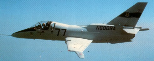
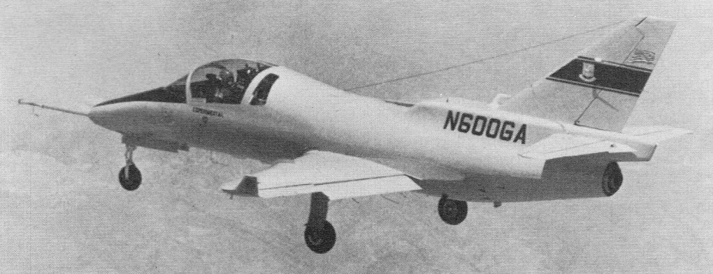
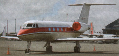
In July 1979 Gulfstream American (later Gulfstream Aerospace) revealed its plans to develop the Peregrine as a military trainer on the basis of its Hustler 500, an unusual executive jet powered by a nose-mounted turboprop and a tail-mounted turbofan. The trainer was based closely on the Hustler 500 without accommodation for passengers in the fuselage, without tip tanks, and with the forward fuselage revised to eliminate the turboprop and provide side-by-side seating for the pupil and instructor. The structure was of the conventional all-metal type with a semi-monocoque fuselage and cantilever low-set wings.
As first flown on 22 May 1981, the Peregrine had drag-reducing Whitcomb winglets on the upper surfaces of the wing tips, though these were later moved to the under surfaces. The engine was located in the rear of the fuselage, and was aspirated via a dorsal inlet whose aft contours formed the structural basis for the swept tail surfaces.
The sole prototype crashed in November 1983, and further development was abandoned. A possible derivative had tandem seating and two 1,500-lb (680-kg) thrust Williams WR44 turbofans, and the details below apply to the planned basic production version.
Type: two-seat primary and basic trainer. Engine: one 3,000-lb (1,361-kg) thrust Pratt & Whitney Canada JT15D-5 turbofan. Maximum speed 454 mph (730 km/h) at 20,000 ft (6,095 m) Initial climb rate 5,200 ft (1,585 m) per minute Service ceiling 48,000 ft (14,630 m) Range 1,243 miles (2,001 km). MTOW: 6,200 lb (2,812 kg). Wing span 34 ft 5.5 in (10.50 m) Length 38 ft 4 in (11.68 m) Height 13 ft 5 in (4.09 m).
Gulfstream completed the Gulfstream V Integration Test Facility and rolled out the GV – the first ultra-long range business jet – in 1995, which first flew in November 1995.
The GV demonstrator flew a distance of 7999 mi / 12,973 km non-stop on 10 January 1997, carrying four crew and three passengers. In 1997, Gulfstream began the simultaneous manufacture of two different aircraft models – the GIV-SP and the GV. Within a few months of the GV’s first delivery in June 1997, it set nearly 40 city-pair and/or speed and distance records, and its industry team was awarded the 1997 Robert J. Collier Trophy, the highest honor in aeronautics or astronautics in North America.
The GV features a six-screen Honeywell SPZ-8500 electronic flight instrumentation system (EFIS).
New Gulfstream V global business jet; also forms the platform for an ASTOR contender under Lockheed Martin leadership.
In 2001 the USAF leased five Gulfstream Vs as C-37As.
Mid-2001 the GV-SP advanced long-range business jet made its first flight. The prototype went to 41,000 ft and flew near to M0.8.
Gulfstream GV B-8092
Engines 2 x 12,420-lb. s.t. Rolls-Royce Tay turbofans. Gross wt. 70,200 lb Empty wt. 33,400 lb Seats 14-24. Fuel capacity 4,340 USG. Top speed 564 mph. Economy cruise 528 mph. Stall 121 mph. Ceiling 45,000 ft Range 4,952 miles Takeoff run 5,100 ft. Landing roll 3,200 ft.
Engines: 2 x BMW R-R BR 700 Srs. Cruise: 0.885M. Max cruise alt: 51,000ft. Range: 6500 nm. Endurance: 14.5 hr. Crew: 4. Pax capacity: 8.
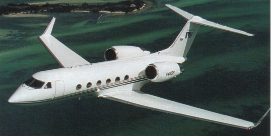
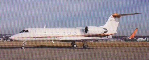
Launched on 19 April 1983, and first flown in September 1985, the Gulfstream IV received its certification by the FAA on 22 April 1987, and went into full production at the Savannah facility of Chrysler Corp subsidiary Gulfstream Aerospace Corp. A twin turbofan executive transport, although generally similar to the Gulfstream III, the IV includes a redesigned wing, a lengthened fuselage with a sixth window on each side and two 13,850 lb st (61,6 kN) R-R Tay Mk.611-8 turbofans. The cockpit incorporates advanced CRT displays and digital avionics. At the time of certification, the company held orders for more than 100 Gulfstream IVs and by the end of May 1987 had delivered 16 aircraft. The complete flight management system, including EFIS, is included in the GIV during production, but, as is customary for corporate aircraft, they are delivered to their customers unfinished and go to approved finishing centres for customer-specified interiors to be installed.
As well as for the corporate role, the GIV is now being vigorously marketed in a number of military and quasi-military roles as the SRA-4 (Special Requirements Aircraft), first flown in 1988. The SRA-4 for mainly military roles including electronic warfare, search and rescue, anti-submarine/ ship, and communications.
The performance of the Gulfstream IV, particularly in payload/range terms, has already been demonstrated in several notable flights, including a round-the-world westbound flight (ie, against the prevailing wind patterns) made in the third production aircraft (s/n 1002). Starting and finishing at Le Bourget during the Paris Air Show, this Gulfstream, with a six-man crew headed by Gulfstream Aerospace chairman Allen E Paulson, completed the l9,847-naut ml (36832.44-km) circuit in 45 hrs 25 mm 10 sec. With five ground stops (at Rome, Mid¬way, Kinabalu, Dubai and Cairo) the aircraft averaged 4377 kts (810,79 km/h) and en¬countered head winds of up to 139 kts (257 km/ h). In addition to 22 city-to-city records, the flight set round-the-world westbound records for jet aircraft of unlimited weight and business jets of up to 35,000 kg (77 140 lb) gross weight.
Gulfstream used company demonstrators N404GA and N400GA to set westbound and eastbound around the world records in June 1987 and February 1988 respectively.
Gulfstream G4SP N600VC
The Gulfstream IV-SP has more efficient engines and modifications revising operating weights and a better payload range combination.
In 1987, the 200th and last Gulfstream III produced was delivered, and the first delivery of a Gulfstream IV took place. The GIV was the first jet in business aviation to have an all-glass cockpit.
Gulfstream G 1159 Gulfstream IV Engine: 2 x Rolls Royce Tay 611-8, 60430 N / 6160 kp Length: 88.255 ft / 26.9 m Height: 24.934 ft / 7.6 m Wingspan: 77.756 ft / 23.7 m Wing area: 950.461 sq.ft / 88.3 sq.m Max take off weight: 73206.0 lb / 33200.0 kg Weight empty: 42512.4 lb / 19280.0 kg Max. weight carried: 30693.6 lb / 13920.0 kg Max. speed: 509 kts / 943 km/h Landing speed: 108 kts / 200 km/h Cruising speed: 459 kts / 850 km/h Initial climb rate: 3937.01 ft/min / 20.0 m/s Service ceiling: 44948 ft / 13700 m Wing loading: 77.08 lb/sq.ft / 376.0 kg/sq.m Range: 3696 nm / 6845 km Crew: 2 Payload: 14-19pax
Gulfstram IV (Long range) Engines: Two Rolls-Royce Tay 610-8 turbofans, 12,420 lb.st (5634 kgp) Fuel capacity, 4,370 US gal (16,540 lt). Max operating speed (VM0) 340 kts (630 km/h) CAS, (MM0) M = 088. Tur¬bulent air penetration speed (above 32,000 ft/ 9754 in), M=075. Max cruising speed, 519 kts (962 km/h) or Mach = 088 Long-range cruise, 459 kts (851 km/h) or M = 080 Take-off balanced field length, 5,100 ft (1 554 m) Initial rate of climb, 3,816 ft/min (19,4 m/sec) Single-engine climb rate, 1,278 ft/min (6,5 m/sec) Max operational altitude, 51,000 ft (15 544 m) Single-engine cruise ceiling, 27,000 ft (8 230 m) Landing distance, 3,200 ft (975 m) Max range (NBAA IFR reserves, long-range cruise), 4,300 naut mls (7965 km) with 8 pax. Typical operating weight empty, 41,100 lb (18 643 kg) Max fuel load, 29,500 lb (13 381 kg) Payload with max fuel, 1,600 lb (726 kg) Max payload, 3,900 lb (1 769 kg) Max take-off weight, 71,700 lb (32 523 kg) Max zero fuel weight, 45,000 lb (20 412 kg) Max landing weight, 58,500 lb (26 536 kg). Wing span, 77 ft 10 in (23,7 m) Overall length, 88 ft 4 in (26,9 m) Overall height, 24 ft 10 in (7,6 m) Wing area, 9504 sq ft (88,29 sq.m) Wing sweepback, at quarter chord line, 2766 deg inboard, 2682 deg outboard. Accommodation: Flight crew of two. Typical executive layouts for 14 passengers; max cer¬tificated, 19 passengers. Cabin length, 45 ft 1 in (13,7 m) Max height, 6 ft 1 in (1,9 m) Max width, 7 ft 4 in (2,2 m) Total cabin volume, 1,513 cu ft (42,8 cu.m) Baggage compartment volume, 169 cu ft (4,8 cu.m).
The Gulfstream line and the Savannah plant were sold to American Jet Industries, which was headed by little-known aviation entrepreneur Allen Paulson.
Paulson became the president and CEO of the company, renaming it Gulfstream America. He made a priority of developing the Gulfstream III, a new aircraft designed to achieve greater range and speed than the GII.
The G.III stretched development of the G.II featured an all new super critical wing.
A declining market caused Grumman to announce the cancellation of the G.III at the 1977 Paris air show. The business was sold to American Jet Industries (later to be Gulfstream Aerospace).
The GIII made its first flight in December 1979, with the first delivery of the aircraft occurring in 1980. It was the first business jet to fly over both poles.
The G-1159A Gulfstream III was first built in 1980
In 1987, the 200th and last Gulfstream III produced was delivered, and the first delivery of a Gulfstream IV took place.
Based on the twin-turbofan Gulfstream III corporate jet, the C-20 Gulfstream III/TV has been purchased for US Air Force, Army, and Navy use as a VIP transport and oper¬ational support aircraft. Three aircraft were bought following an initial period of lease, and have been followed by 12 more. Three maritime patrol aircraft acquired by the Royal Danish Air Force are equipped with APS-127 search radars, INS, and a large cargo door. They can be reconfigured in less than two hours for VIP transport, troop carrying, or medevac. Another export customer, reported to be India, has bought three reconnaissance versions. Prod-uction of the Spey powered Gulfstream III ended in early 1987 with the transition to the Gulfstream IV, which uses Tay engines.
A Gulfstream III completed as the SRA-l de¬monstrator first flew on 14 August 1984 from Travis Field, Savannah, Georgia. It had been extensive¬ly tested with a number of the sensor systems proposed for some of the SRA-4 roles, including an under fuselage Side-Looking Airborne Modular Multimission Radar.
In 1987, the 200th and last Gulfstream III produced was delivered, and the first delivery of a Gulfstream IV took place.
G-1159A Gulfstream III Engines: 2 x Rolls/Royce Spey 511-8, 11,400 lbs thrust. Seats: 22. Length: 83.1 ft. Height: 24.2 ft. Wingspan: 77.8 ft. Wing area: 935 sq.ft. Wing aspect ratio: 6. Maximum ramp weight: 68,700 lbs. Maximum takeoff weight: 68,700 lbs. Standard empty weight: 32,200 lbs. Maximum useful load: 36,500 lbs. Zero-fuel weight: 42,000 lbs. Maximum landing weight: 58,500 lbs. Wing loading: 73 lbs/sq.ft. Power loading: 3 lbs/lb. Maximum usable fuel: 28,300 lbs. Best rate of climb: 3800. Certificated ceiling: 45,000 ft. Max pressurisation differential: 9.5 psi. 8000 ft cabin alt @: 45,000 ft. Maximum single-engine rate of climb: 1200 fpm @ 225 kts. Single-engine climb gradient: 327 ft/nm. Single-engine ceiling: 27,000 ft. Maximum speed: 501 kts. Normal cruise @ 45,000ft: 442 kts. Fuel flow @ normal cruise: 2475 pph. Stalling speed clean: 121 kts. Stalling speed gear/flaps down: 105 kts. Turbulent-air penetration speed: 270 kts.
SRA-1 Engines: 2 x Rolls/Royce Spey 511-8, 11,400 lbs thrust.
The Gulfstream I, the first of its kind designed specifically for business travel, was a success in the business world, prompting Grumman to develop a jet-powered corporate aircraft called the Gulfstream II or GII.
Announced on 17 May 1965, the G.II was to have a maximum range of 3670 mi / 5907 km.
The Grumman Gulfstream II was originally designed as a business jet, but an enlarged version would eventually serve in feeder airline use. Production of the swept-wing Model II version with turbofan engines started in 1965, and the first delivery was in 1967. It is one of the larger business jets, with a gross weight of 58,000 pounds. It is also one of the fastest, with a top speed of 589 mph, and it has a long-range capability of up to 3,600 miles.
The 200th Gulfstream II was delivered in 1977. In 1981, Gulfstream introduced the Gulfstream GIIB. The GIIB had a modified GII fuselage and the GIII wings, complete with winglets. The variant offered weight and performance characteristics similar to the GIII, but with the shorter GII fuselage. Gulfstream completed and delivered approximately 40 GIIBs. The 256th and final GII delivery took place in 1977.
Gulfstream II 1959 Engines: 2 x RR Spey Mk.511-8 turbofan, 11,400 lb. Seats: 12/19. Wing loading: 80.9 lb/sq.ft. Pwr loading: 2.87 lb/hp. Empty wt. 29,000 lb Max TO wt: 65,500 lb. Operating wt: 36,900 lb. Equipped useful load: 28,207 lb. Payload max fuel: 907 lb. Zero fuel wt: 42,000 lb. Range max fuel/cruise: 1701 nm/3.2 hr. Range max fuel / range: 4009 nm/ 10.2 hr. Service ceiling: 43,000 ft. Top speed 588 mph Max cruise: 512 kt. Max range cruise: 395 kt. Vmc: 89 kt. Stall: 108-130 kt. 1.3 Vso: 140 kt. ROC: 4350 fpm. SE ROC: 1525 fpm @ 214 kt. SE Service ceiling: 24,500 ft. BFL: 5700 ft. Cabin press: 9.45 psi. Fuel cap: 23,300/27,300 lb. Takeoff run 5,000 ft. Landing roll 3,190 ft.
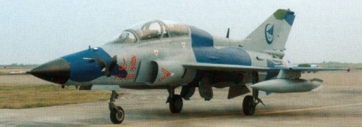
In 2001, Guizhou began development of a new trainer aircraft to replace the JJ-7 (MiG-21) trainers and better prepare pilots for flying the J-11 (Su-27) and J-10. To reduce costs and development time, Guizhou based their design off of the JJ-7. It uses the same fuselage and wings of the late-model JJ-7s, while radically redesigning the forward fuselage. The intakes were moved to the sides of the fuselage, allowing for a solid nose holding a radar. To improve the view for the instructor, the tandem cockpits were stepped. While intended as a trainer, it retains secondary attack capabilities. It comes standard with an ECM suite and a radar warning receiver, as well as an inflight refueling probe. Armament consists of an internal 23mm cannon and five hardpoints for unguided air-to-ground munitions and short-range AAMs.
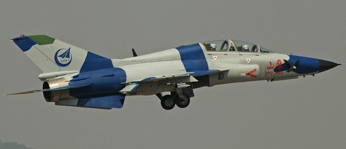
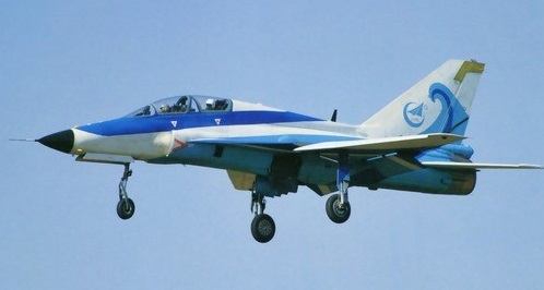
Also known as the FTC-2000 Mountain Eagle, on December 13, 2003, the JL-9 derivative of the JJ-7 first flew, from An Shun/Huang Guo Shu (AVA) airport. Involving little change from the JJ-7, the JL-9 took 28 months from design to first flight.
The PLAAF began service trials of the JL-9 in 2006, while Guizhou continued to upgrade the onboard systems. In 2009, the JL-9 passed trials, and began production.
Meanwhile a navalized variant for the PLANAF has arose, incorporating several major modifications. The nose intakes were modified to prevent engine stalls at high angles of attack, the vertical stabilizer and leading-edge root extensions were enlarged, and the ventral fins were deleted to make space for the landing hook.
The WS-13 Taishan (WoShan-13) is a turbofan engine designed and manufactured by Guizhou Aircraft Industry Corporation to power the Pakistan-China jointly developed JF-17 Thunder light-weight multi-role fighter, and in the near future the Shenyang J-31 fifth generation stealth fighter currently under development.
China began development of the Taishan in 2000 to replace the Klimov RD-93 turbofan, which had been selected in the 1990s to power the JF-17 light-weight fighter. It is designed to have a life span of 2,200 hours and an improved version, providing around 100 kN (22,450 lb) of thrust with afterburner, was under development.
First run in 2006, the WS-13 Taishan was certified in 2007 and serial production began in 2009. The 18 March 2010 edition of the HKB report stated that a FC-1 equipped with the WS-13 completed its first successful runway taxi test.
Officials at the Farnborough International Airshow in August 2010 stated that a JF-17 development aircraft is flying with a Chinese engine, which is most likely to be the WS-13.
In November 2012, Aviation Week reported that a JF-17 Thunder is flying in China with the Guizhou WS-13 engine.
Variants: WS-13 – 86 kilonewtons (19,000 lbf) thrust with afterburner. WS-13A (upgraded) – 100 kilonewtons (22,000 lbf) thrust with afterburner.
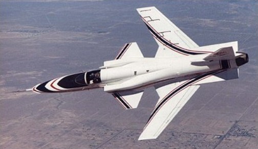
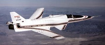
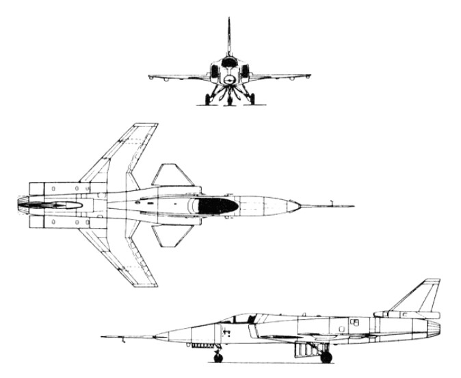
Grumman Aerospace, Rockwell International and General Dynamics, proposed to DARPA that a for-ward swept wing demonstrator should be built. The demonstrator would be used to: verify that composites could provide the wing stiffness required without severe weight penalties; verify the aerodynamic advantages of a forward swept wing indicated in wind tunnel testing; and expand the forward swept wing technology base. DARPA responded favourably and there followed three years of intensive competitive design studies, culminating in Grumman Aerospace being selected to build two demonstrators in 1981 under an $80 million contract, based on their Project Design G 712. This was officially designated X 29A by the U.S. Air Force in mid 1981. The X-29A was a single-seat jet aircraft fitted with a wing mounted at the rear of the fuselage, swept forward at 35 degrees, and having shoulder-mounted canards just behind the cockpit. To save development time and money, Grumman used as many parts as practical from existing aircraft. The forward fuselage and nose landing gear are from a Northrop F 5A (the 15th built from the mid-1960s), and the main landing gear and control surface actuators are from a General Dynamics F 16A. Off the–shelf equipment includes the emergency power unit and the flight control servo actuators, also from an F 16A. The aircraft is powered by a single General Electric F404 after burning turbofan, developing 16,000 lb. thrust, and is the engine type used in the McDonnell Douglas F/A 18 Hornet. The tapered variable incidence foreplane was selected after intensive wind tunnel testing and is used to provide pitch trim and control movements, as this type of surface provides lift for trim. It also acts as a slat to help the heavily loaded inboard section of the wing. The X 29A is a highly unstable aircraft, the c.g. being no less than 35% aft of the aerodynamic centre of the wing/canard surfaces. Initially the planned instability was intended to be only 20%, and accordingly the canard had an area equal to 15% of the wing. Wind tunnel tests, however, showed that this would not give the degree of control required during transonic manoeuvres, and the canard size was increased to 20% of the wing, giving the current degree of instability. The heart of the X 29A is its distinctive forward swept wing. It is a very thin wing; the thickness to-chord ratio being less than 5%. The wing area is 188 sq. ft. and the angle of forward sweep 30 deg.
Ultimately, the X-29 emerged with three digital channels so that any two could detect a failure in a third, plus a fourth, analogue backup channel which could control the aircraft over a limited flight envelope. The main role of the fourth channel was to protect the aircraft in case some unsuspected freak software mode disabled all three digital channels simultaneously.
The inboard end of the leading edge is swept aft, to alleviate some of the root stall problems associated with forward sweep. To preserve the structural integrity of the vital lower wing skin, the main landing gear retracts forward, into the fuselage ahead of the wing. The trailing edge of each wing root extends aft to form a large body strake ending in a controllable flap. The strakes add area behind the c.g. and hence improve directional stability. It is on the outer, forward swept portion of the wing that the unique directional properties of carbon fibre laminates construction are used to overcome the adverse wing twist, or “divergence”, without the prohibitive weight penalty of a conventional aluminium alloy structure. A total of 752 plies is used, with 156 layers at the thickest section of the skin. To resist the natural tendency of the forward swept wing to twist, the layers are “rotated” some 10 deg. forward of the wing’s structural axis. The laminated wing skins, at an angle to the bending axis, shear forward under compression and back¬ward under tension. The effect of shearing under load on the wing torsion box is to generate a nose down torque which counters the natural tendency of the wing to twist leading edge up. The carbon fibre skins are attached to a sub structure of conventional aluminium alloy construction, the front spar being of electron-beam welded titanium to cater for the high loads on the front part of the wing due to the forward sweep. Full span “variable camber” flaperons are fitted to the wing trailing edge, these being used symmetrically for pitch control and asymmetrically for roll. The flaperons are in three sections, being hinged at two chord wise locations, so that they may be used to change the camber of the wing. The primary hinge is at 75% chord and the secondary hinge is at 90% of the chord. The flap sections are geared so that for every 1 deg. of flap deflection the aft section deflects an additional 1 deg. The flap increases manoeuvrability and reduces drag across the entire speed range. Programmed by the flight control computer, the flap alters the wing shape in flight as a function of changing conditions. The result is a constantly optimum wing shape.
The core of the wing structure is an electron-beam-welded box of titanium and light alloy, providing an exceptionally sturdy but generally conventional basis for the outer aerodynamic surfaces. The latter are single-piece upper and lower skins made of carbon fibre reinforced plastics up to 156 layers thick at the inboard ends. The skins are exceptionally light yet rigid, and can sustain violent manoeuvres without any possibility of aeroelastic divergence. The leading edges are fixed, with no provision for high-lift devices of any kind, but the trailing edges are fitted with full-span flaperons that can be used as camber-changing sections. Located aft of the wing are the conventional rudder, plus a pair of strake flaps fitted at the extreme rear of the extended wing root trailing edges, nearly in line with the rudder. Powerful canard foreplanes with one-fifth of the wings’ area are located on the sides of the lateral inlets, and just forward of the inboard sections of the wing leading edge, which are conventionally swept back. The canards are driven through a triple-redundant fly-by-wire flight-control system, and are the aeroplane’s primary control surfaces in the pitching plane. The canards are used to trim out any tail up pitching moment by generating lift, augmenting the lift of the wing. Flight tests have confirmed wind-tunnel predictions about the X-29’s flight characteristics: even at extreme high angles of attack the aircraft cannot be stalled and it retains full roll authority down to very low speeds. Early flight trials also indicated that fuel burn was lower than expected, an indication of extremely low drag.
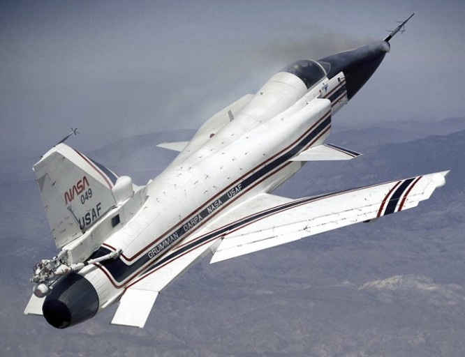
The X 29A flew for the first time on 14th December 1984, from NASA’s Dryden Flight Research Facility at Edwards Air Force Base, California, with Grumman chief test pilot Chuck Sewell at the controls. For this first flight, which lasted 57 minutes, the landing gear and the variable camber trailing edge devices were kept down. The gear and flaps were retracted during the second flight on 4th February 1985. Two further flights were made on 25th February and 1st March. Two 360 deg. rolls were made during the third flight. After just these four flights the demonstrator was turned over to NASA in March 1985 for further flight testing. In the initial phase of testing low altitude, high speed manoeuvres, the X 29 demonstrated high g turns tighter than anything achieved by a conventional fighter and displayed awesome potential for combat aircraft. For an extended test phase, the second aircraft was fitted with a vortex flow control system to test the possibility of using high pressure nitrogen injected directly into the vortices coming off the nose to help maintain control at high AoA. With this, pilots were able to achieve good control response to an AoA of 67 degrees.
The first aircraft (83-0003) flew on 14 December 1984, piloted by Charles Sewell, but was grounded on 6 December 1988 after its 242nd flight. The second X-29A (83-0049), flown for the first time on 23 May 1989, completed its flight test programme in October 1991. Between them the two aircraft completed 374 flights (more than any other X-craft) and demonstrated angles of attack up to 67 degrees (the target was 80). They also flew at Mach numbers up to 1.52 and reached altitudes up to 12200m. Both aircraft were now in store at the Ames-Dryden Flight Research Facility of NASA at Edwards AFB, California.
X 29A Engine: 1 x General Electric F404 GE 400 after burning turbofan, 69847 N / 16,000 lb. s.t. Wing span: 27 ft. 2.5 in. / 8.3 m Length: 16.4 m / 53 ft 10 in Height: 14 ft. 3.5 in. / 4.4 m Wing area: 17.5 sq.m / 188.37 sq ft Foreplane area: 35.96 sq.ft. Empty wt: 13,800 lb. / 6260.0 kg MTOW: 17,800 lb. / 8074.0 kg Max. payload weight : 12819.9 lb / 5814.0 kg Max speed: Mach 1.6 approx. Ceiling: 15300 m / 50200 ft Crew: 1
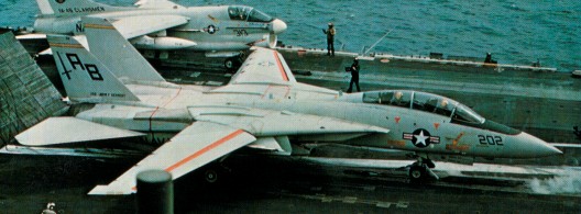
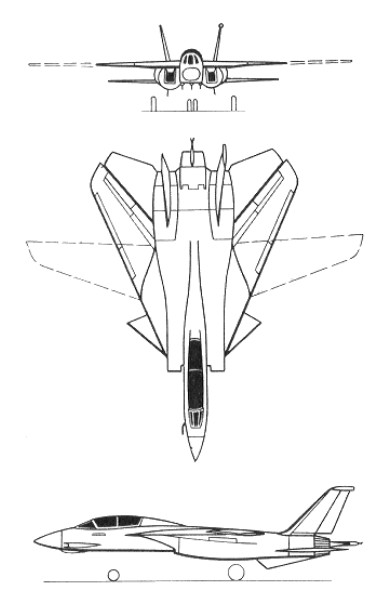
The F-14 Tomcat is a supersonic, twin-engine, variable sweep wing, two-place fighter designed to attack and destroy enemy aircraft at night and in all weather conditions.
The F-14 can track up to 24 targets simultaneously with its advanced weapons control system and attack six with Phoenix AIM-54A missiles while continuing to scan the airspace. It can also deliver free-fall or guided bombs. Unique to the F-14 is the AWG-9 doppler radar which can track 24 targets simultaneously and engage six. These six targets can then be attacked with the AIM-54 Phoenix long range missile. The Phoenix can only be fired by the F-14 and it is the only long range standoff air-air missile employed by the United States armed forces. The F-14 also features a maximum speed of over Mach 2 and automatically sweeping wings which enhance the plane’s ability to maintain control in the air. The first R&D aircraft was flown on 21 December 1970, and the production F-14A is powered by two Pratt & Whitney T1730-P-412A turbofans each having a maximum reheat rating of 20,900 lb (9 480 kg). Armament consists of an internally housed 20-mm M-61 A1 rotary cannon and (intercept mission) six AIM-7E/F Sparrow and four AIM-9G/H Sidewinder AAMs, or six AIM54A Phoenix and two Sidewinder AAMs.
US Navy F-14A
The first of 478 F-14A aircraft entered US Navy service in October 1972 and saw it’s first operational flight in September 1974. Tomcats first went to sea on board the aircraft carriers USS Enterprise and USS John F. Kennedy in 1974 75. By 1980 more than 340 of the 521 Tomcats expected to be purchased for the US Navy had been delivered. Power is provided by two 20,900 lb thrust (with afterburning) Pratt & Whitney TF30 P 412A turbofan engines, and armament can include one 20 mm General Electric M61A 1 cannon and four Sparrow or Phoenix air to air missiles under the fuselage, plus two more Sparrow or Phoenix missiles and two Sidewinders, or four Sidewinders under the fixed section of the wings. Alternatively, up to 14,500 lb (6,577 kg) of weapons can be carried for ground attack.
Delivered from September 1974, initial Pratt & Whitney TF30-P-414A-powered F-14As experienced problems from fan-blade failures and compressor stalls, the latter often at high angles-of-attack, leading to numerous irrecoverable “departures from controlled flight”. Usually in the form of flat spins, these contributed to annual losses peaking to 9-10 in the 1970s-80s, but diminishing somewhat when F110-GE-400 turbofans were introduced in F-14Ds. GEC-Marconi digital flight-control systems and Martin-Baker zero-zero ejection-seats brought further F-14 safety improvements, although compressor stalls were not entirely eliminated. A total of 377 had been delivered to service by the beginning of 1981. A total of 79 F-14 A models were exported to Iran 1976-78. The Imperial Irani Air Force during the reign of the Shah of Iran ordered 80 aircraft, but only 79 were delivered, as the last unit was embargoed and turned over to the United States Navy. The original F-14A was soon found to be slightly underpowered, and handicapped by engine reliability problems. Two prototypes were built with Pratt & Whitney F401-P-400 turbofans as F-14Bs, but the F-14B did not enter production. The F-14C was an unbuilt version with F401-P-400s and new avionics. One of the F-14Bs was later re-engined with the General Electric F101 (now F110-GE-400) as the F-14DFE to serve as the prototype F-14A (Plus). Thirty-eight of these aircraft are being newly built, and 32 F-14As are being re-engined. The F-14A+ (later designated F-14B) entered service in 1987. The F-14D Super Tomcat first took to the air on February 9, 1980. The upgrade included enhanced APG-71 radar and cockpit, a dual IRST/TV undernose pod, and increased AAM capability. The Tomcat has now been equipped for night-attack bombing duty with the use of a LANTIRN (Low Altitude Navigation and Targeting InfraRed for Night) pod. The upgrade allows the F-14 to remain in service until the arrival of the F/A-18E/F Super Hornet.
Production of the F-14A ship-borne interceptor will switch to the A(Plus) model in FY1987, and to the D version in FY1988. The F-14A(Plus)/F-14D development programme was initiated in July 1984, and consists principally of upgrades to the F-14A radar, avionics, and power plant systems, together with integration of the ALQ-165 airborne self-protection jammer, the Jtids secure datalink, an infrared search and track sensor (IRST), and the LAR-67 threat warning and recognition system. The new radar, the APG-71, based on the F-14A’s AN/AWG-9 system, includes a high-speed digital signal processor. These upgrades will be incorporated into production Tomcats in two stages. The first will involve the engine upgrade only, the F-14A’s TF30 power plant being replaced by the General Electric F110 turbofan in some FY1987/1988 procured aircraft which will be known as F-14A(Plus). The second step combines the engine upgrade with the new radar and avionics, the resulting aircraft becoming the F-14D. F-14D procurement begins in FY1988. In September 1986 the US Navy revised its F-14A(Plus)/F-14D purchase plans. Only seven production A(Plus) will now be acquired, two in FY1987 and five in FY1988, to be followed by a total of 127 Ds instead of the 304 originally planned. Seven F-l4Ds are to be funded in FY1988, and 12 per year will be procured there¬after until the planned total is reached. The first production F-14A(Plus) is scheduled for delivery in November 1987, followed by the F-14D from March 1990. Approximately 400 F-14A/A(Plus) Tomcats will be retrofitted with F110 engines and upgraded equipment to give an all-D-model F-14 fleet by 1998.
On 4 January 1989 two US Navy F-14 downed two Libyan MiG-23.
The USN lost nearly 170, mainly from accidents rather than operational attrition over Iraq and elsewhere.
F-14 retirement was accelerated by it being the USN’s most costly combat aircraft to operate, from requiring 40-60 maintenance man-hours (MMH) per flight-hour. This compares with 10-15 MMH for the latest Boeing F/A-18E
The US Navy planned to retire its Mach 2.34 multi-role Grumman F-14s, when VF-31, the last Tomcat squadron, begins conversion to Boeing F/AA8E/F Super Hornets at NAS Oceana, Virginia, in September 2009. The F-14 was formally retired from the US Navy on 22 September 2006.
F-14 Tomcat Engines: 2 x GE F110 GE400, 27,800 lb Wingspan Open: 64 ft. 0 in Wingspan Swept: 38 ft. 0 in. Length: 61 ft. 9 in Weight Empty: 40,100 lb Max. Weight: 74,350 lb Payload: 14,500 lb Range: 1,842 mi Fuel External: 4,070 lb Fuel, Internal: 17,340 lb Ceiling: 55,000 ft Climb Rate: 45,000 fpm Max. Speed: 1,585 mph Cruise Speed: 610 mph Hardpoints: six Cannons: 1x 20 mm Crew: 2
F-14A Tomcat Engines: 2 x P&W TF30-P-412A or -414A turbofan. Installed thrust (reheat): 20,900 lb st. / 92.97 kN Span (max), 64 ft 1.5 in (19,55 m), (min) 37 ft 7 in (11,45 m). Length, 61 ft 11 in (18,90 m). Height: 16 ft (4,88 m). Wing area: 565 sq ft (52,50sq.m). Tactical radius (internal fuel and four Sparrow AAMs), 450 mls (725 km). Empty wt: 18,290 kg. MTOW: 68,567 lb (31 101 kg). Empty equipped wt: 40,070 lb (18 176 kg). Warload: 8618 kg. Max level speed at 10.975m (36,000 ft) Mach 2.37 or 2.517 km/h (1,564 mph) Service ceiling: 17,070+m (56,000+ ft) TO run: 427 m. Ldg run: 884 m. Fuel internal (external): 7174 kg (1720 kg ). Air refuel: Yes. Armament: 8 x AAM / 14225kg, 1 x 20 mm M61A1 Vulcan six-barrel cannon with 675 rounds. Crew: 2
F-14A+ Tomcat Engine: 2 x General Electric F110-GE-400 turbofan, 23,100 lb st.
F-14B Tomcat Engine: 2 x Pratt & Whitney F404-P-400 turbofan
F-14D Tomcat Engine: 2 x General Electric F110-GE-400 turbofan, 23,100 lb st.
F-14DFE Tomcat Engine: 2 x General Electric F101 turbofan
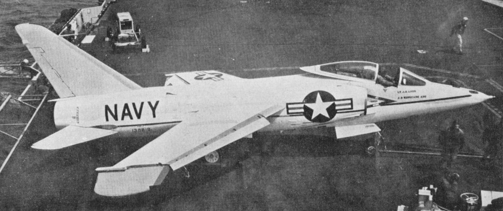
The US Navy’s first transonic shipboard warplane, development of the G-98 was ordered on 27 April 1953 as a revised and improved F9F-6. In the event, there was no commonality with the earlier fighter, but nevertheless, when the first example was flown on 30 July 1954, it was designated YF9F-9, this being changed to F11F-1 in April 1955.
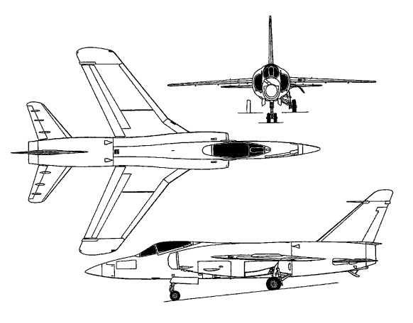
The airframe had mid-set wings sweptback at 30 degrees. There are swept-back tail surfaces, with an all-moving tailplane mid-set on the fuselage. No ailerons are fitted. Lateral control being by spoilers. Leading edge slats are fitted. Trailing-edge flaps are over the full span except for the folding tip portions. Finger type air-brakes are under the fuselage. Two underwing jettisonable fuel tanks may be fitted.
The tricycle under-carriage has a single wheel on each main unit and twin-wheel nose unit. The main wheels retract forward and into the fuselage, and the nose wheels retract rearward.
Able to fly supersonic in level flight, the F11F-9 Tiger was in production for the U.S. Navy in 1955. Six prototypes and 39 F9F-9 were ordered initially. Difficulties with the intended afterburning Wright J65-W-6 engine dictated installation of the derated J65-W-18 in the production F11F-1 with a maximum military thrust of 7,450 lb (3379 kg) and 10,500 lb (4 763 kg) with full reheat. In consequence, the F11F-1 failed to meet contractual performance guarantees.
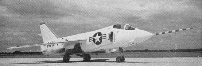
F11F-1 Tiger
A small number of pre-production aircraft, each with a Wright J65-W-6 turbojet engine with afterburner, were followed by 39 production aircraft (ordered with J65-W-4 afterburning engines).
Grumman F11F-1
The last two Tigers of the initial production batch were fitted with the General Electric YJ79-GE-7 turbojet rated at 9,600 lb (4 355 kg) military thrust and 15,000 lb (6 804 kg) with reheat as F11F-1Fs. One of the F11F-1Fs attained a speed of 1,963km/h and set a short-lived height record on 18 April 1958 of 23,449m.
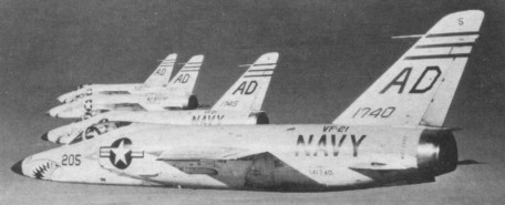
A further contract for J65-W-18-engined Tigers placed for the US Navy brought the total number of F11F-1s built to 201, but these were gradually phased out of first-line service from 1959. Those which remained in second-line service when the tri-service designations became rationalised in 1962 were redesignated F-11A.
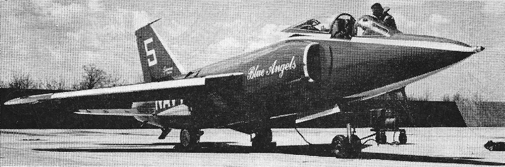
F-11A Tigers of Blue Angels 1965
Production was limited to 201 aeroplanes, the last being delivered in March 1957, service phase-out commencing in 1959.
F11F-1 Engine: 1 x Wright J-65-W-6, 33.8kN Max speed, 753 mph (1212 km/h) at sea level. Initial climb, 16,300 ft/min (82,8 m/sec). Range, 1,108 mls (1783 km). Service ceiling: 16700 m / 54800 ft Empty weight, 13,307 lb (6 036 kg). Max loaded weight, 23,459 lb (10 641 kg). Span, 31 ft 8 in (9,65 m). Length, 44 ft 10.75 in (13,68 m). Height, 13 ft 2.75 in (4,03 m). Wing area, 250 sq ft (23,22 sq.m). Armament: four 20-mm cannon. Crew: 1
F11F-1 Engine: 1 x Wright J-65-W-18, 10,500 lb Span, 31 ft 8 in (9,65 m). Wing area, 250 sq ft (23,22 sq.m). Length, 44 ft 10.75 in (13,68 m). Height, 13 ft 2.75 in (4,03 m). Empty weight, 13,307 lb (6 036 kg). Max loaded weight, 24,078 lb Max speed, 740 mph / M1.12 at 35,000 ft Service ceiling: 50,500 ft Range, 600 mls Armament: four 20-mm cannon. Hardpoints: 4 Crew: 1
F11F-9 Tiger Naval fighter Crew: 1 Engine: Wright J65-W-7 Sapphire turbojet, with afterburner, 7500 lb. thrust. Wingspan: 31 ft. 5 in Length: 39 ft. Loaded weight: approx. 14,000 lb.