Between 1949-1952 the Hughes Aircraft Company built and tested the XH-17 heavylift helicopter, designed as a “flying crane” for the USAF. The largest helicopter ever built, the XH-17 was originally a Kellett design.
First flown in 1949, it was subsequently abandoned; but test-flying was restarted late in 1954.
Power: 2x 5,000 lb. thrust Allison J35 turbojets. Rotors: 2-blade tip-powered main; 2-blade tail. Rotor diameter: 130 ft. Loaded weight: 52,000 lb. Ceilng: 15,000 ft. Typical range: 40 miles at 60 mph
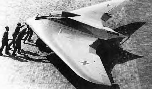
In February 1945 a committee under Professor Bock with representatives from Junkers, Messerschmitt and Horten, deliberated over the optimum design for a 4 jet engined bomber. Designs by Junkers (Ju 287. A swept forward tailed aircraft), Messerschmitt (Project 1107 as swept back tailed aircraft), and Horten (swept back tailless) were considered, and a joint report issued giving the committee’s opinion on the best estimate for relative performance. Junkers published the report. The specification to be noted was for 900 kph at 10 km height and a range of 3,000 km using four H 11 jets. According to Horten the committee decided that his machine, given the same top speed as the others would have more range and less landing speed. (125 kph against the 175 kph for the others.) Alternatively he could carry 8 tons (metric) of bombs against the 4 by his competitors for the same range. The dimensions of the aircraft were roughly as follows:
Horten said the agreed CDo for this aircraft was 0.0078 excluding Mach number correction. In the structural design he reckoned to save 6% of the all up weight (spar and rib weight) compared with the conventional type. He thought the committee a bit unfair because they insisted on increasing his estimate of structure weight by about a ton. All the above figures were remembered by Horton, who used them as a rough illustration. They are not accurate.
In 1943, Reichsmarschall Göring issued a request for design proposals to produce a bomber that was capable of carrying a 1,000 kilograms (2,200 lb) load over 1,000 kilometres (620 mi) at 1,000 kilometres per hour (620 mph); the so-called “3×1000 project”. Conventional German bombers could reach Allied command centers in Great Britain, but were suffering devastating losses from Allied fighters. At the time, there was no way to meet these goals—the new Junkers Jumo 004B turbojets could provide the required speed, but had excessive fuel consumption.
The Hortens concluded that the low-drag flying wing design could meet all of the goals: by reducing the drag, cruise power could be lowered to the point where the range requirement could be met. They put forward their private project, the H.IX, as the basis for the bomber. The Government Air Ministry (Reichsluftfahrtministerium) approved the Horten proposal, but ordered the addition of two 30 mm cannons, as they felt the aircraft would also be useful as a fighter due to its estimated top speed being significantly higher than that of any Allied aircraft.
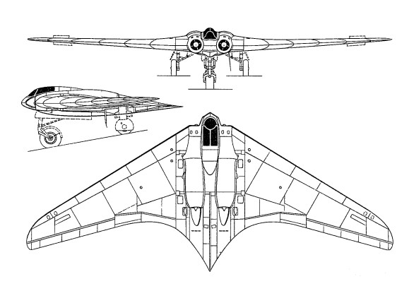
Horten IX
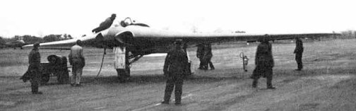
The H.IX was of mixed construction, with the center pod made from welded steel tubing and wing spars built from wood. The wings were made from two thin, carbon-impregnated plywood panels glued together with a charcoal and sawdust mixture. The wing had a single main spar, penetrated by the jet engine inlets, and a secondary spar used for attaching the elevons. It was designed with a 7g load factor and a 1.8× safety rating; therefore, the aircraft had a 12.6g ultimate load rating. The wing’s chord/thickness ratio ranged from 15% at the root to 8% at the wingtips. The aircraft utilized retractable tricycle landing gear, with the nosegear on the first two prototypes sourced from a He 177’s tailwheel system, with the third prototype using an He 177A main gear wheelrim and tire on its custom-designed nosegear strutwork and wheel fork. A drogue parachute slowed the aircraft upon landing. The pilot sat on a primitive ejection seat. A special pressure suit was developed by Dräger. The aircraft was originally designed for the BMW 003 jet engine, but that engine was not quite ready, and the Junkers Jumo 004 engine was substituted.
Control was achieved with elevons and spoilers. The control system included both long-span (inboard) and short-span (outboard) spoilers, with the smaller outboard spoilers activated first. This system gave a smoother and more graceful control of yaw than would a single-spoiler system.
The first two of the type were built at Gottingen.
Four aircraft of the H IX type were started, designated V.1 to V.4.
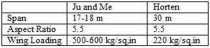
V.1 was the prototype, designed as a single seater with twin B.M.W. 109-003-1 jets, which were not ready when the airframe was finished. It was accordingly completed as a glider with fixed tricycle landing gear and extensively test flown at Oranienburg during the summer of 1944. D.V.L. instrumented it for special directional damping tests to determine its suitability as a gun platform. First flown on 1 March 1944, flight results were very favorable, but there was an accident when the pilot attempted to land without first retracting an instrument-carrying pole extending from the aircraft.
The design was taken from the Horten brothers and given to Gothaer Waggonfabrik. The Gotha team made some changes: they added a simple ejection seat, dramatically changed the undercarriage to enable a higher gross weight, changed the jet engine inlets, and added ducting to air-cool the jet engine’s outer casing to prevent damage to the wooden wing.
Göring believed in the design and ordered a production series of 40 aircraft from Gothaer Waggonfabrik with the RLM designation Ho 229, even though it had not yet taken to the air under jet power. The first flight of the H.IX V2 was made in Oranienburg on 2 February 1945. All subsequent test flights and development were done by Gothaer Waggonfabrik. By this time, the Horten brothers were working on a turbojet-powered design for the Amerika Bomber contract competition and did not attend the first test flight. The test pilot was Leutnant Erwin Ziller. Two further test flights were made between 2 and 18 February 1945. Another test pilot used in the evaluation was Heinz Scheidhauer (de).
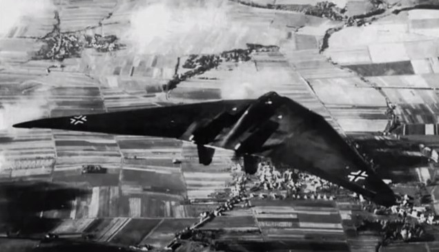
The H.IX V2 reportedly displayed very good handling qualities, with only moderate lateral instability (a typical deficiency of tailless aircraft). While the second flight was equally successful, the undercarriage was damaged by a heavy landing caused by Ziller deploying the brake parachute too early during his landing approach. There are reports that during one of these test flights, the H.IX V2 undertook a simulated “dog-fight” with a Messerschmitt Me 262, the first operational jet fighter, and that the H.IX V2 outperformed the Me 262. Two weeks later, on 18 February 1945, disaster struck during the third test flight. Ziller took off without any problems to perform a series of flight tests. After about 45 minutes, at an altitude of around 800 m, one of the Jumo 004 turbojet engines developed a problem, caught fire and stopped. Ziller was seen to put the aircraft into a dive and pull up several times in an attempt to restart the engine and save the precious prototype. Ziller undertook a series of 4 complete turns at 20° angle of bank. Ziller did not use his radio or eject from the aircraft. He may already have been unconscious as a result of the fumes from the burning engine. The aircraft crashed just outside the boundary of the airfield. Ziller was thrown from the aircraft on impact and died from his injuries two weeks later. The prototype aircraft was completely destroyed after 2-hours flying.
V.3 was being built by Gotha at Friedrichsrodal as a prototype of the series production version. The V3 was larger than previous prototypes, the shape being modified in various areas, and it was meant to be a template for the pre-production series Ho 229 A-0 day fighters, of which 20 machines had been ordered. The V3 was meant to be powered by two Jumo 004C engines, with 10% greater thrust each than the earlier Jumo 004B production engine used for the Me 262A and Ar 234B, and could carry two MK 108 30 mm cannons in the wing roots.
Work had also started on the two-seat Ho 229 V4 and Ho 229 V5 night-fighter prototypes, the Ho 229 V6 armament test prototype, and the Ho 229 V7 two-seat trainer. The Ho 229 V4 two-seat all-weather fighter, was in construction at Friedrichroda, but not much more than the center-section’s tubular framework completed as was the Ho 229 V5 two-seat all-weather fighter. The Ho 229 V6 projected definitive single-seat fighter version with different cannon, mock-up was in production at Ilmenau.
The Ho 229 A-0 projected expedited production version based on Ho 229 V6 was not built. The H.IXb (also designated V6 and V7 by the Hortens) projected two-seat trainer or night-fighter; not built.
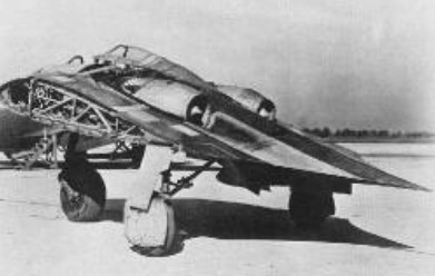
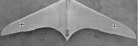
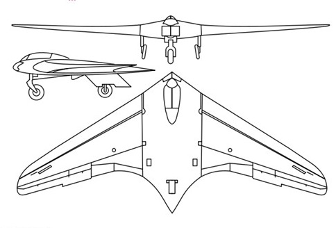
In shape, the H IX was a pure wing with increased chord at the center to give sufficient thickness to house the pilot and the jet units, which were placed close together on either side. The H IX started as a private venture and the Hortens were very anxious to avoid failure so they avoided aerodynamic experiments wherever possible. A lower sweepback was used than on the H V and H VII and laminar flow wing sections were avoided as a potential source of trouble. Wing section at the junction with the center sections was 14% thick with maximum thickness at 30% and 1.8% zero Cmo camber line. At the centerline thickness was increased locally to 16% to house the crew. The tip section was symmetrical and 8% thick. Horten also believed that since the compressibility cosine correction to drag was based on the sweepback of the maximum thickness line, the ordinary section would show little disadvantage. Wing twist was fixed by consideration of the critical Mach number of the underside of the tip section at top speed. This gave a maximum washout of 1.8°. Having fixed this, the CG was located to give trim at CL = 0.3 with elevons neutral. In deciding twist for high speed aircraft, CD values were considered in relation to local CL at operational top speed and altitude (10 km in the case of the H IX). Twist was arranged to give minimum overall drag consistent with trim requirements. The wing planform was designed to give a stall commencing at 0.3 to 0.4 of the semi-span. Wing structure comprised a main spar and one auxiliary spar or wooden construction with ply covering. The center section was built up from welded steel tube. Wing tips were all metal. The undercarriage was completely retractable and of tricycle type the front wheel folding backwards and the main wheels inwards. The nose wheel was castering and centered with a roller cam. When resting on the ground, wing incidence was 7° and the nose wheel took about 40% of the total weight.
The jet engines were installed at -2° to the root chord and exhausted on the upper surface of the wing at 70% back from the nose. To protect the wings the surface was covered with metal plates aft of the jet pipe and cold air bled from the lower surface of the wing by a forward facing duct and introduced between the jet and the wing surface. The installation angle was such that in high speed flight the jest were parallel to the direction of flight. Lateral and longitudinal control was by single stage elevon control flap with 25% Frise nose and compensating geared tap balance. (This system was also used on the H VII, see para. 4.6.) The pilots control column was fitted with a variable hinge point gadget, and by shifting the whole stick up about 2” the mechanical advantage could be doubled on the elevons for high-speed flight. Directional control was by drag rudders. These were in two sections, slight movements of the rudder bar opening the small (outboard) section and giving sufficient control for high speed. At low speeds when courser control was necessary the large movement also opened the second spoiler, which started moving when the small one was fully open. By pressing both feet at once, both sets of spoilers could be operated simultaneously; this was stated to be a good method of steadying the aircraft on a target when aiming guns. The Hortens stated that the spoilers caused no buffeting and claimed an operating force of 1 kg for full rudder, with very little variation in speed. A change was made from the original H VII parallel link system to improve the control force characteristics. With the new system, aerodynamic forces could be closely balanced by correct venting of the spoiler web, leading the main control load to be supplied by a spring. The cover plate of the spoilers was spring loaded to form an effective seal with the rudders closed; this device was used on most Horten spoiler and dive brake designs. On further models of the H IX it was proposed to fit the “trafficator” type rudder tried experimentally on the H VII.
Landing flaps consisted of plain trailing edge flaps (in four sections) on the wings, with a 3% chord lower surface spoiler running right across the center section, which functioned as a glide path control. The outer pair of plain flaps lowered 27° and the inner pair 30° – 35° on the glider version V.1. On V.2 mechanical trouble prevented the inner pair operating and all flying was done with the outer pair only. The center section spoiler could be used as a high speed brake and gave 1/3 g at 950 kph. No dive recovery flap was considered necessary. Proper performance tests were not done on V.2 before its crash and top speed figures were calculated values, checked by Messerschmitts. The following figures were remembered by Reimar Horten: All Up Weight, Including Ammunition and Armour: 8,500 kg (18,700 lbs.) All Up Weight, Excluding Ammunition and Armour: 7,500 kg Wing Area: 52 sq.m (566 sq.ft.) Wing Loading: 33 lb./sq.ft. Fuel (I2 Crude Oil): 2,000 kg (4,400 lbs.) Performance at 7,500 kg (16,500 lbs.) Takeoff Run: 500 m Takeoff Speed (10 deg Flap): 150 kph (95 mph) (Note: This corresponds to a CL of 1.30 which is the stated stalling CL of the aircraft.) Top Speed (at Sea Level): 950 kph (590 mph) (CDo estimated to be 0.011) Calculated ceiling was 16 km (52,000 ft). Engines would not work above 12 km as the burners went out. Rate of Climb at Sea Level: 22 m/sec (4,300 ft/min) In tests against the Me 262 speeds of 650-700 kph (400-430 mph) were obtained on about 2/3 throttle opening. This appears to be the only flight test figure available. Messerschmitt sent performance calculators to the Horten works to check their estimates. The method suggested by D.V.L. for getting the sweepback correction to compressibility drag was to take an area of 0.3 x the root chord squared at the center section as having no correction applied, and then apply full cosine correction over the outer wing. Sweepback angle was defined as that of the quarter chord locus. Test data was available for CDv. for zero sweepback. The Messerschmitt method was to base sweepback on the max t/c locus and to scale Mach number by the square root cos Ø. The H IX V.1 was flown by Walter Horten, Scheidhauer and Ziller. Scheidhauer did most of the flying (30 hours) at Oranienberg, Horten and Ziller flew for about 10 hours. D.V.L. instrumented the aircraft for drag and directional stability measurements. No drag results were obtained because of trouble with the instrument installation – apparently an incidence measuring pole was fitted which could be lowered in flight and glide path angle was obtained from the difference between attitude and incidence measurements. One day they landed without retracting the pole. Directional oscillation tests were completed successfully and an advance report was issued (10 pages of typescript) by Pinsker and Lugner fo D.V.L. The essence of the results was that the lateral oscillation was of abnormally long period – about 8 sec. At 250 kph and damped out in about 5 cycles. At low speeds the oscillation was of “dutch roll” type but at high speed very little banking occurred. Many fierce arguments took place at D.V.L. on desirable directional stability characteristics, the Hortens naturally joining the “long period” school of thought. They claimed that the long period would enable the pilot to damp out any directional swing with rudder and keep perfectly steady for shooting. It was found that by using both drag rudders simultaneously when aiming, the aircraft could be kept very steady with high damping of any residual oscillation. Lateral control was apparently quite good with very little adverse yaw.
Longitudinal control and stability was more like a conventional aircraft than any of the preceding Horten types and there was complete absence of the longitudinal “wiggle” usually produced by flying through gusts. Tuft tests were done to check the stall but the photographs were not good enough for much to be learned. Handling was said to be good at the stall, the aircraft sinking on an even keel. There seems to be some doubt, however, as to whether a full stall had ever taken place since full tests with varying CG and yaw had not been done. Although the stick was pulled hard back, the CG may have been too far forward to give a genuine stall. Directional stability was said by Scheidhauer to be very good, as good as a normal aircraft. He did not discuss this statement in detail as he was obviously very hazy about what he meant by good stability and could give very little precise information about the type and period of the motion compared with normal aircraft. Scheidhauer had flown the Me 163 as a glider and was obviously very impressed with it; he was confident enough to do rolls and loops on his first flight. We asked him how the H IX V.1 compared with the 163; he was reluctant to give an answer and said the two were not comparable because of the difference in size. He finally admitted that he preferred the 163 which was more maneuverable, and a delight to fly (he called it “spielzeug”).
The H IX V.2 with two Junkers 109-004B-1 jet engines was flown at Oranienburg only by Ziller and completed about 2 hours flying before its crash. The redesigned Ho IX V2 demonstrated speeds of up to 960km/h before it was destroyed. This occurred after an engine failure – the pilot undershot, tried to stretch the glide and stalled. One wing must have dropped, for the aircraft went in sideways and Ziller was killed. Before the crash a demonstration had been given against an Me 262; Horten said the H IX proved faster and more maneuverable, with a steeper and faster climb.
In spite of the crash, Horten thought the single engine performance satisfactory and said the close spacing of the jets made single engined flying relatively simple. Such promise encouraged the RLM to instruct Gothaer Waggonfabrik to assume development of the design, and a third prototype, the Go 229 V3, was produced with 1000kg thrust Jumo 109-004C turbojets, but was prevented from flying by the end of hostilities in May 1945.
V3
Work had also started on the two-seat Go 229 V4 and Go 229 V5 night-fighter prototypes, the Go 229 V6 armament test prototype, and the Go 229 V7 two-seat trainer, No progress had been made on 20 pre-production Go 229A-0 fighter-bombers, on order at the end of the war, that were intended to carry two 1000kg bombs and four 30mm MK 103 cannon.
Production was assigned to the Gothaer Waggon Fabrik, which main facilities were placed in the city of Gotha. An initial contract for 20 pre-production aircraft was awarded to the firm and works begun. The Gotha engineers introduced several and extensive modifications to adapt the design to the series production. The construction was subcontracted to the Ortlepp Möbel Fabrik at Friedrichroda. This was a logical solution as the GWF facilities had all their capabilities compromised in the production of parts for other aircraft manufacturers. Besides its management was pushing the RLM to adopt their flying wing designs and this way cancel the Horten IX series production. The Gotha designs were known as the Gotha P-60 with three different versions A, B and C. When the Ortlepp Works at Friedrichsroda were overrun by troops of the American 3rd Army’s VII Corps on April 14, 1945 they found inside of the building three FW in different construction stages: The V3 was nearly complete. The jet engines were installed and most part of the works on the skin had finished.
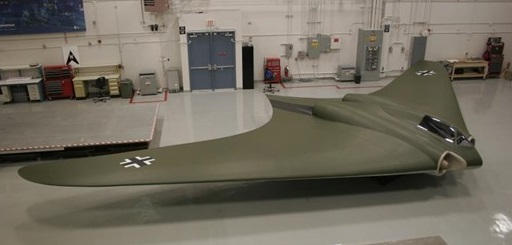
After the end of the war, the V4 and V5 disappeared. In some reports they are briefly mentioned but it’s quite likely that they were scrapped. The V1, the non-powered prototype, was also destroyed and last seen at Kassel Rothwesten airfield. We do not know where in Europe the V3 was taken, where it was crated and loaded in a ship. According to the NASM the HMS Reaper packing list is not known, but there were other vessels with war booty that left Europe. What is sure is that the V3 was shipped to the USA and arrived by train to Freeman. Today, the Horten IX V3 is in store at the Garber Building 22 awaiting a restoration.
Ho-IX V2 Engine: 2 x 2 x Jumo-004, 900kg Take-off weight: 6900 kg / 15212 lb Empty weight: 4844 kg / 10679 lb Wingspan: 16.76 m / 55 ft 1 in Length: 7.46 m / 24 ft 5.75 in Height: 2.6 m / 8 ft 6 in Wing area: 52.8 sq.m / 568.33 sq ft Max. speed: 960 km/h / 597 mph Crew: 1
Horten Ho 229A / V3 manufacturer’s estimates Powerplant: 2 × Junkers Jumo 004B turbojet, 8.7 kN (1,956 lbf) each Wingspan: 16.76 m (55 ft 0 in) Wing area: 50.20 m² (540.35 ft²) Length: 7.47 m (24 ft 6 in) Height: 2.81 m (9 ft 2 in) Empty weight: 4,600 kg (10,141 lb) Loaded weight: 6,912 kg (15,238 lb) Max. takeoff weight: 8,100 kg (17,857 lb) Maximum speed: 977 km/h (estimated) (607 mph) at 12,000 metres (39,000 ft) Service ceiling: 16,000 m (estimated) (52,000 ft) Rate of climb: 22 m/s (estimated) (4,330 ft/min) Wing loading: 137.7 kg/m² (28.2 lb/ft²) Thrust/weight: 0.26 Armament: 2 × 30 mm MK 108 cannon Bombload: 2 × 500 kilograms (1,100 lb) bombs / R4M rockets Crew: 1
Go 229A 0 Engines: two 1000 kg (2,205 lb) thrust Junkers Jumo 109 004C turbojets. Maximum speed 1000kph (621mph) at 6100 m (20,015 ft) Landing speed 130 kph (81 mph) Maximum take off weight: 8500 kg (18.739 lb) Wingspan 16.78 m (55 ft 5/8 in) Length 7.47 m (24 ft 6 1/8 in) Wing area: 51.5sq.m (554.36 sq.ft). Armament: four 30 mm MK 103 cannon and up to 2000 kg (4,409 lb) of bombs.
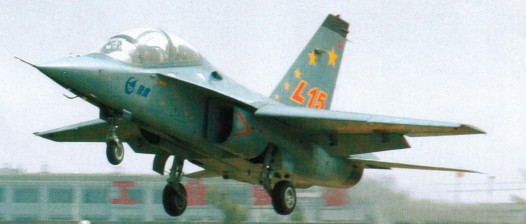
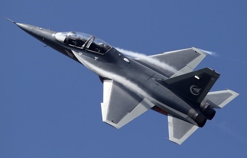
In the early 2000s, Hongdu began work on an entirely new advanced trainer, assisting in the project was Yakovlev OKB. The L-15 has a composite structure and features a digital quadruple fly by wire, glass cockpit, and hands on throttle and stick flight control. The aerodynamic performance is enhanced by large leading edge extentsions, which give a maximum angle of attack of 30 degrees. The aircraft can also have four underwing and two wingtip hardpoints.
The L-15 made its maiden flight on March 13, 2006. The L-15 was in competition with the JL-9 for the PLAAF. Chief test pilot for the project was Colonel Zhang Jingting.
Hongdu has marketed the airframe abroad with some success – Zambia and Venezuela having ordered small numbers.
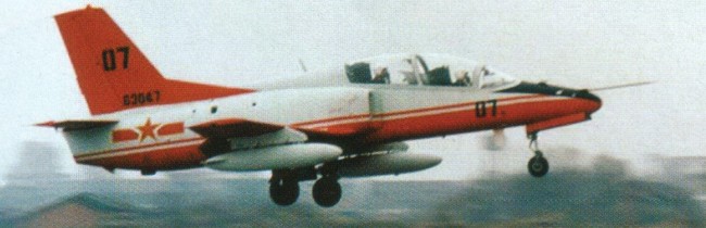
The JL-8 trainer was proposed as a two-seat intermediate jet trainer and light attack aircraft joint cooperation effort between the governments of Pakistan and the People’s Republic of China in 1986. The name was changed on the suggestion of Pakistan’s then President General Zia ul Haq to Karakorum-8 to represent the friendship between the two countries. Work on the design started in 1987 at Nanchang Aircraft Manufacturing Company (NAMC) at Nanchang, Jiangshi Province in South Central China. The Chinese chief designer of the aircraft was Mr. Shi Ping (石屏), heading a team of over 100 Chinese Engineers, while Air Cdr Muhammad Younas Tbt (M), SI(M) was the chief designer from the Pakistani side leading a team of over 20 Pakistani engineers.
Initially, the aircraft was to feature many United States parts, including Garrett TFE-731 engine and several cockpit displays along with communication and avionics systems, but due to political developments and an embargo from the US at the end of the 1980s following the Tiananmen Square protests of 1989, other vendors had to be used.
The JL-8 / K-8 has a multi-role capability for training and, with little modification, can also be used for airfield defense. The aircraft is supposed to be as cost-effective as possible, with a short turn-around time and low maintenance requirements. The JL-8 for the domestic Chinese market and its export variants, K-8E and K-8P, have different powerplants and avionics.
A low-wing monoplane design primarily constructed of aluminum alloys, the JL-8 / K-8 airframe structure is designed for an 8,000 flight hour service life.
The landing gear is of tricycle configuration, with hydraulically operated wheel brakes and nose-wheel steering. The flight control system operates a set of conventional flight control surfaces with a rigid push-rod transmission system, which itself is electrically or hydraulically operated. The aileron control system, of irreversible servo-control type, is composed of a hydraulic booster, an artificial-feel device, a feel trim actuator and a rigid push-rod transmission mechanism. The elevator and rudder control systems are of reversible push-rod type.
The JL-8 / K-8 cockpit arrangement is designed to be as close to that of a combat aircraft as possible. A transparent plastic canopy covering both cockpits, which are arranged in a tandem seating position, is supposed to give a good all-round field of view.
A Rockwell Collins Electronic Flight Instrument System (EFIS) is fitted, with multi-function displays (MFDs) in the front and rear cockpits showing information to the pilots. The emergency cockpit escape system is made up of two Martin-Baker MK-10L rocket-assisted ejection seats which are zero-zero capable, meaning they can be used safely at zero altitude and zero speed. Although JL-8 is designed to have limited capability to deliver air-to-ground weapons, the first rocket attack practice was only completed in May 2011.
Ultra high frequency (UHF) and very high frequency (VHF) radio communication systems along with a Tactical Air Navigation (TACAN) and automatic direction finder (ADF) and instrument landing system (ILS) were available.
A strap-on Environmental control system (ECS) from AlliedSignal provides air conditioning to the cockpit. It is capable of operating when the aircraft is on the ground, under ambient temperatures of -40 to +52 °C, as well as in the air.
The JL-8, for the Chinese domestic market, was originally powered by the Ukrainian Ivchenko-Progress AI-25TLK turbofan jet engine with 16.9 KN of thrust, but this has been replaced by the WS-11, the Chinese-manufactured copy of the AI-25TLK. Export variants (K-8P, K-8E) use the lower powered Honeywell TFE731-2A-2A modular turbofan, which has digital electronic engine control (DEEC) with 15.6 KN thrust, provided the US government approves sale of the engine to the customer.
A hydro-mechanical fuel control system delivers fuel to the engine. The aircraft’s fuel system consists of the fuel tanks and the fuel supply/transfer, vent/pressurization, fuel quantity measuring/indicating, fuel refueling and fuel drain subsystems. The total fuel is contained in two fuselage bladder-type rubber tanks and a wing integral tank of 1720 lb. The capacity of each drop tank is 250 litres. Two 80 gal fuel drop-tanks can be mounted on outboard under-wing hardpoints
The first prototype was built in 1989, with the first flight taking place on 21 November 1990 by Chief Test Pilot Col Yang Yao (杨耀). Flight testing continued from 1991 to 1993 by a Flight Test Team consisting of four Chinese and two Pakistani Pilots (Group Captain Waqar Ahmad and Squadron Leader Nadeem Sherwani).
After four prototypes were built, production of a small batch of 24 aircraft was launched in 1992. Chinese share out of these was 18, while Pakistan Air Force (PAF) received six K-8s in 1994. In 1995, PAF decided to order 75 more K-8s to gradually replace its fleet of Cessna T-37 Tweet basic trainers. In 2010, the number of K-8 aircraft in PAF were estimated to be around 40. The People’s Liberation Army Air Force (PLAAF) received its first six JL-8 trainers in 1995 following additional upgrades. The Chinese model uses WS-11, a Chinese-manufactured version of the Ukrainian Ivchenko AI-25 (DV-2) engine. The PLAAF is anticipated to continue adding the JL-8 trainer to its fleet to replace its obsolete trainers, such as the Chengdu JJ-5. In 2008, the number of JL-8s in PLAAF inventory were estimated to be over 120 aircraft.
Other nations have shown interest in the trainer and it also served in the air forces of Egypt, Sri Lanka and Zimbabwe. While the type primarily serves as a basic cum advanced trainer, it can also be used in the close air support or even air combat role when appropriately armed.
The export-variant K-8 Karakorum Basic Common Advanced Jet Trainer is co-produced by China National Aero-Technology Import & Export Corporation (CATIC) for export markets other than Pakistan, while later aircraft for Pakistan have been built by the Aircraft Manufacturing Factory (AMF), Pakistan Aeronautical Complex. The latest export variant is the K-8P version, which currently is operated by the PAF. The K-8P has an advanced avionics package of integrated head-up display (HUD), multi-function displays (MFDs) and comes equipped with MFD-integrated GPS and ILS/TACAN systems. It also features Armament racks for carrying a variety of training and operational bombs up to 250 KG, pod mounted 23 mm canon as well as PL-5 / 7 /AIM-9 P launchers. Studies for putting a Griffo Radar in the nose were under way. In September 2011, NAMC rolled out another 12 K-8P for undisclosed foreign client.
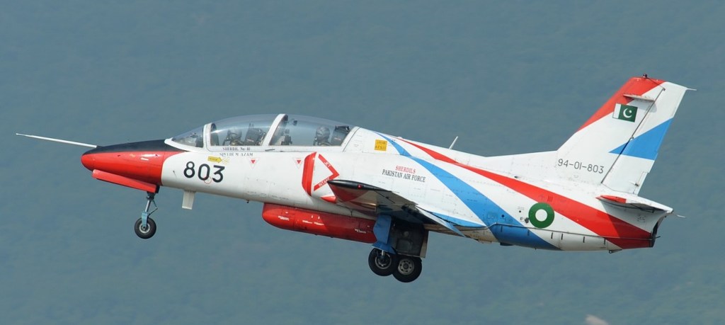
The K-8 took part in its first aerial display in 1993 at the Singapore Air Show and since then has participated at Air Shows at a number of places including Dubai, Paris, Farnborough, Bangkok, Zuhai etc. It was shown to the Pakistani public for the first time on 23 March 1994 at the Pakistan Day Parade. It became part of the Sherdils (Lion Hearts) aerobatics team of the Pakistan Air Force in 2009 and carried out its first public display on 6 April 2010. K-8 replaced the team’s previous T-37 Tweet aircraft.
K-8 of the Pakistan Air Force aerobatics team, Sherdils, Zhuhai Air Show 2010 in China
In 2008 Venezuela announced the purchase of 18 K-8 aircraft. The K-8 was being marketed by China to the air forces of the Philippines; and to Indonesia, as a replacement for Indonesia’s BAE Hawk jet trainers. In 2009, the Bolivian government approved a deal to purchase 6 K-8P aircraft for use in anti-drug operations. The total number of K-8 aircraft produced till 2010 in all variants were estimated to be over 500, with production rate of approximately 24 aircraft per year continuing.
Other operators include the Ghana Air Force (4), Myanmar Armed Force (12× K-8 delivered with additional 48 on order), Namibian Air Force (12), People’s Liberation Army Air Force (190× JL-8 delivered as of February 2011, out of 400 ordered), Sri Lanka Air Force (5× K-8 delivered with additional 2 on order, Sudanese Air Force (12), Venezuelan Air Force (17 Another 9 K-8V on order as of October 2013), Zambian Defence Force (15), Air Force of Zimbabwe (11), and Tanzanian Air Force (6).
The Pakistan Air Force operated 60 K-8 aircraft (12 K-8s and 48 K-8Ps), which served as intermediate jet trainers with the No. 1 Fighter Conversion Unit, Mianwali and as basic jet trainers with the Pakistan Air Force Academy, Risalpur. Another 32 K-8Ps were on order as of January 2012.
In late December 2012 and early January 2013, during the Kachin conflict, Burma Air Force K-8s have been used to strike Kachin rebel’s positions in the north of the country.
Incidents: At 9am on 5 September 2008, a K-8 Karakorum trainer of the Air Force of Zimbabwe crashed over the town of Gweru, killing both pilots. The aircraft was on a routine training sortie. On 21 July 2010, a K-8 Karakorum trainer of the Venezuela Air Force crashed just 4 months after its delivery. The pilots ejected and managed to survive. On 20 August 2011, two Zimbabwe Air Force K-8’s collided in mid-air while taking part in a fly past at the funeral of retired General Solomon Mujuru. Pieces were seen to fall from the aircraft, but they both appeared to land safely. On 23 October 2012, a K-8 Karakorum training plane lost directional control during take off from Julius Nyerere International Airport, Dar es Salaam. Both pilots ejected but one of them was killed on impact. The plane left the runway and struck a container. On 27 November 2012, a K-8 Karakorum belonging to Venezuela’s Bolivarian Air Force, suffered a malfunction and crashed near the El Libertador Air Base, in the Palo Negro parish of the city of Maracay, Aragua state. Both pilots ejected and suffered only minor injuries. The plane was scheduled to participate on the air show to celebrate Venezuelan Air Force Day, later that day. On 26 July 2013 at 12:50 A.M., a K-8 Karakorum belonging to Venezuela’s Bolivarian Air Force, crashed in the Gen. Rafael Urdaneta Air Base, near Maracaibo, Zulia State, while participating in night exercises. The pilot, First Liutenent Milenia Bolivar, ejected and was transported to a local hospital, where she is said to be in good condition.
Variants:
K-8 Original variant powered by the Garrett TFE731-2A turbofan engine.
K-8E K-8 variant developed for export to Egypt in 1999, featuring 33 modifications to the airframe and avionics. Built in Egypt from Chinese-supplied kits, production of 80 Egyptian-built Chinese kits was completed in 2005, with license production of an additional 40 K-8Es undertaken thereafter.
K-8P Pakistan-specific variant with new avionics, glass cockpit and Martin Baker Zero-Zero ejection seats.
K-8V An ‘integrated flight test simulation aircraft’ (IFTSA), equipped with an advanced flight control computer and analogue fly-by-wire (FBW) system which can mimic the aerodynamic characteristics and flight profile of other aircraft. Used primarily to test aircraft designs before prototypes are built and tested.
JL-8 PLAAF-specific variant powered by the Ivchenko AI-25 TLK turbofan and featuring Chinese avionics suite. First flew in December 1994, 6 aircraft delivered to PLAAF in June 1998.
L-11 Variant of JL-8 powered by the WS-11 turbofan (Ivchenko AI-25 TLK produced under license in China). Approximately 100 aircraft delivered to PLAAF.
JL-8W (K-8W) Variant of the JL-8 with improved cockpit and HUD. Delivered to Venezuela’s Bolivarian Military Aviation March 13, 2010, with no U.S.-controlled parts. Total order 18 aircraft (+ 40 announced).
JL-8VB (K-8VB) Variant similar to JL-8W; for export to Bolivian Air Force (6), with no U.S.-controlled parts. Total order 6 aircraft (+ 12 announced).
Specifications:
K-8 Powerplant: 1 × Garrett TFE731-2A-2A turbofan, 16.01 kN (3,600 lb) Wingspan: 9.63 m (31 ft 7 in) Length: 11.6 m (38 ft 0 in) Height: 4.21 m (13 ft 9 in) Empty weight: 2,687 kg (5,924 lb) Max. takeoff weight: 4,330 kg (9,546 lb) Wing loading: 254.40 kg m-2 Maximum speed: Mach 0.75 (800 km/h, 498 mph) Range: 2,250 km (1,398 mi) Service ceiling: 13,000 m (42,651 ft) Max. airframe load factor: +7.33 g / -3.0 g Crew: 2 (in tandem) Armament: 1× 23 mm cannon pod (mounted on centreline hardpoint) Hardpoints: 5, total capacity 1,000 kg (2,205 lb) external fuel and ordnance: 4× under-wing, capacity 250 kg each 1× under-fuselage (23 mm cannon pod mount)
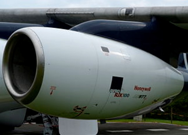
The Honeywell LF 507 is a geared turbofan engine produced by Lycoming, AlliedSignal and then Honeywell Aerospace. The earlier ALF 502 was certified in 1980. The improved, higher-thrust LF 507 was used on the Avro RJ update of the British Aerospace BAe 146.
LF 507-1H Type: High bypass geared turbofan Length: 65.5 in (166 cm) Diameter: Fan: 40.25 in (102 cm) Dry weight: 1385 lb (628 kg) Compressor: Single stage fan, 2 stage axial low pressure compressor, 7 stage axial and single stage centrifugal high pressure compressor Combustors: Annular Turbine: Two stage high pressure turbine, two stage low pressure turbine Maximum thrust: 7,000 lbf (31 kN) Overall pressure ratio: 13.8:1 Bypass ratio: 5.3:1 Specific fuel consumption: 0.406 lb/lbf-h (41.4 kg/kN-hr) Thrust-to-weight ratio: 5.1:1
LHTEC (Light Helicopter Turbine Engine Company) is a joint venture between Rolls-Royce and Honeywell founded in 1985. The company was originally a partnership between the Allison Engine Company and AlliedSignal Aerospace . In 1995 Rolls-Royce acquired Allison, and AlliedSignal merged with Honeywell in 1999, and adopted its name.
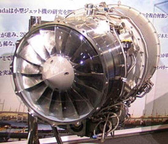
The GE Honda HF120 is a small turbofan engine for the light-business jet market.
The HF120 turbofan is the first engine to be produced by GE Honda Aero Engines. Developed from the Honda HF118, the HF120 was undergoing an extensive testing program, with formal certification testing scheduled to begin in late 2008. The engine has a wide-chord swept fan, two-stage low-pressure compressor and counter rotating high-pressure compressor based on a titanium impeller. Evolved from Honda’s HF118, the engine demonstrates a 2,050 lbf takeoff thrust. The engine touts environmental performance, striving to meet and exceed future environmental standards for business jet engines. Greater fuel efficiency and reduced emissions are two of the results of the engine’s lightweight design.
Specifications: Type: Turbofan engine Length: 44 in (111.8 cm) Diameter: maximum: 21.2 in (53.8 cm) Dry weight: <400 pounds (180 kg) Maximum thrust: takeoff thrust: 2,050 lbf Specific fuel consumption: <0.7 Thrust-to-weight ratio: >5:1
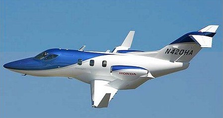
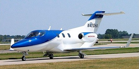
The HondaJet made its maiden flight in North Carolina in December 2003. Honda’s six seat business jet is powered by a lightweight low-emission turbine engine that has been in development since 1988.
It features a graphite composite fuselage, laminar flow wing and two Honda HF118 turbofans mounted on overwing pylons. Delivery of the first plane is planned for the third quarter of 2012.
Engines: 2 x 820kg GE-Honda HF118 turbofans Max take-off weight: 4173 kg / 9200 lb Wingspan: 12.20 m / 40 ft 0 in Length: 12.52 m / 41 ft 1 in Height: 4.01 m / 13 ft 2 in Max. speed: 800 km/h / 497 mph Cruise speed: 778 km/h / 483 mph Ceiling: 12497 m / 41000 ft Range: 2037 km / 1266 miles Crew: 2 Passengers: 5-6
At the Atlantic Aero FBO at Greensboro, North Carolina’s Piedmont Triad International Airport (KGSO), a team of engineers and technicians assembled a twin-engine very light business jet. This was the proof-of-concept (POC) prototype of what would become the HondaJet very light jet. The team’s work culminated on Dec. 3, 2003, when the POC took flight.
This was a relatively small team of engineers and technicians that had been working furiously for at least the last 10 months—and some much longer—in preparation for that day.
There were no electrical system drawings, only conceptual schematics, and they had to create them from scratch.
They had a very small group in the early days of the project in Greensboro and a larger team in Japan supporting them. Work hours during the design phase started early and extended into the evening, day after day. In three years, they accomplished a tremendous amount of work and overcame huge challenges with the limited staff getting the aircraft ready for its inaugural flight.
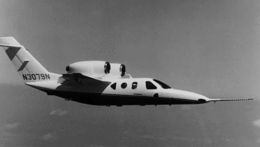
The second production jet to feature over-the-wing-mounted (OTWEM) turbofan engines, the HondaJet was the brainchild of Honda’s Michimasa Fujino. Fujino spent years exploring aircraft design, culminating in flight testing of the composite twin-engine MH02, which had two engines mounted directly on top of a wing attached to the top of the fuselage.
He eventually settled on the HondaJet OTWEM design because of its efficiency and the extra space it afforded in the aft cabin, but persuading the head office that this was the best configuration proved to be a huge challenge. It took more than two years to reach the point and finally the OTWEM configuration for HondaJet was fixed.
At midnight and, with the flight scheduled for 8 a.m., the aircraft was prepped and ready to go. However, back in at 5:30 a.m., firing up the aircraft to make sure everything was still okay before the preflight.
Michimasa Fujino’s first design was the MH02, which didn’t go into production.