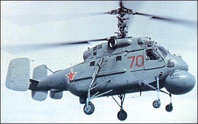
The Ka-27 came in four versions, the Ka-27, 28, 29, and 32. The Ka-29 and Ka-29TB are assault transport helicopters. In 1973 in response to a Navy requirement the OKB started the design and construction of a transport/attack derivative of the Ka-27 – the Ka-29 shipboard helicopter. Deputy Chief Designer S.N.Fomin was entrusted with heading the design effort. Leading designer G.M.Danilochkin became his assistant, while B.V.Barshevsky was appointed leading engineer of the test programme.
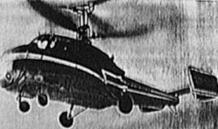
Ka-252TB prototype (also known as Izdelie D2B or Izdelie 502) first flew 28 July 1976 with test pilot Ye.I.Laryushin at the controls, possibly with a Ka-25 nose or original narrow Ka-27/Ka-32 nose. Production at Kumertau (KAPP) from 1984.
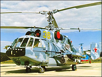
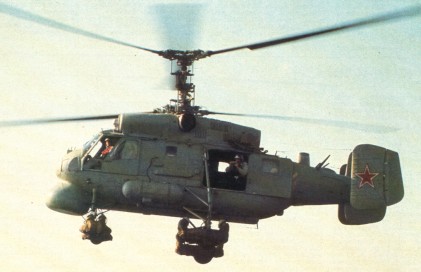
Powered by two Klimov TV3-117VMA turboshafts, each of 1,633kW, the engines are started by APU and fuel tanks are filled with reticulated polyurethane foam for fire suppression. The Ka-29 has a wider flight deck than the Ka-27 for a crew of two. Three flat-plate windscreen glazings instead of a two-piece curved transparency, and 350kg of armour ia around the cockpit and engines. The main cabin has a port-side door, aft of the landing gear, divided honzontally into upward- and downward-opening sections. The lower section forming steps when open. The cabin can hold up to 16 assault troops, four stretcher patients, seven seated casualties and medical attendant in ambulance role, and with internal or slung cargo provisions.
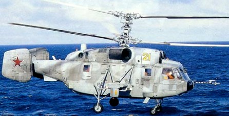
The basic airframe is of the Ka-27 with a broader flight deck, and E-801 or E-801M (export) Oko (eye) early warning radar system by Radio Engineering Institute, Nizhny Novgorod, including large rotating radar antenna (area 6.0sq.m). It stows flat against underfuselage and deploys downward, turning through 90 degrees into vertical plane before starting to rotate at 6 rpm. The landing gear retracts upward to prevent interference, nosewheels into long fairings. Once the system has been switched on, the antenna extended and operation mode selected, data on air targets flying below the helicopter’s altitude are acquired, evaluated and transmitted automatically to command centre, requiring only two crew (pilot and navigator, latter monitoring – but not operating – the system) in the helicopter. The Ka-29 is fitted with a Kronshtadt Kabris GPS navigation and display system. Loiter speed is 100 to 120km/h at up to 3,500m; loiter duration 2h 30 min. Maximum surveillance radius is 100 to 150km for fighter-size targets, or 250km for surface vessels, with up to 20 targets tracked simultaneously. The antenna can be retracted manually or explosively jettisoned in the event of a forced landing. Two large panniers were on the starboard side of cabin, fore and aft of the main landing gear on helicopter numbered 032 (forward panniers only on 031). The hatch window is deleted above the starboard rear pannier, and a new TA-8Ka APU positioned above the rear of the engine bay fairing, with slot-type air intake at the front of the housing, displacing the usual ESM and IR jamming pods, and gives the radar and antenna an independent power supply. Tyre size 620×180 on main wheels, 480×200 on nosewheels. Tailcone extended by fairing tor flight recorder; no armour, stores pylons or outriggers.
The Ka-29 armament in the Ka-29TB assault version comprised anti-tank guided missiles, gun pods, unguided rockets, free-fall bombs and submunitions dispensers. The transport version could accomodate 16 fully-armed troops or carry outsize loads weighing up to 4000kg on a sling and was armed with a rapid-firing 7.62-mm machine-gun. Comparing the test results of the single-rotor Mi-24 and the co-axial Ka-29 equipped with the same models of sights, fixed gun armament and unguided rockets, weapon accuracy on the Ka-29 proved to be approximately twice as high. In 1987 G.M.Danilochkin was awarded the State Prize for his role in the development of the Ka-29’s weapons system. Armament was a four-barrel Gatling-type GShG-7.62 7.62mm machine gun, with 1,800 rounds, flexibly mounted behind down ward-articulated door on starboard side of nose; four pylons on outriggers, for two four-round packs of 9M114 Shturm (AT-6 ‘Spiral’) ASMs and two UV-32-57 57 or B-8V20 80mm rocket pods. Alternative loads include four rocket packs, two pods each containing a 23mm gun and 250 rounds, or twn ZAB 500 incendiary bombs. Internal weapons bay for torpedo or bombs. Provision fur 30mm Type 2A42 gun above port outrigger, with 250-round ammunition feed from cabin.
The State acceptance trials were completed in May 1979 and production began in 1984. The Ka-29 entered service with the Northern and Pacific Fleets in 1985 and were photographed on board the assault ship Ivan Rogov in the Mediterranean in 1987. At the time they were thought to be the Ka-27B and were given the NATO reporting name ‘Helix-B’. Identified as the Ka-29 combat transport at Frunze (Khodinka) Air Show, Moscow, August 1989.
The Ka-29TB (‘Helix-B’) armed derivative for day/night, VFR and IFR, transport and close support of seaborne assault troops has in-the-field conversion from one role to the other. With non-retractable landing gear and a 50cm wider armoured flight deck, the were reportedly used by the Experimental Combat Group in the Chechen War in 1996. The Ka-33 is a civilianised version of Ka-29TB shipborne assault transport. The designation was revealed at the Moscow Air Show in August 1997.
The Ka-29RLD radar picket helicopter was developed as the Ka-31.
A total of 59 Ka-29s were built, for Russian Federation Naval Aviation (about 45) and Ukrainian Navy (about 12).
Ka-29 Engine: 2 x Klimov TV3-117V. Instant pwr: 1642 kW. Rotor dia: 15.9 m. Length: 11.6m Height: 5.40m Empty weight: 5520kg MTOW: 11,500 kg. Payload: 2000 kg (external payload 4000 kg). Max speed: 151 kt / 250km/h Max cruise: 127 kts. Range with 2000kg payload: 460km Range with max fuel: 740km HOGE: 12,131 ft. Service ceiling: 14,098 ft / 5000m Crew: 2 Pax: 16
The design process started in 1969, with the prototype first flown on 24 December 1973, replacing the Ka-25 Hormone ship-borne helicopter, the Ka-27 Helix entered service in 1980 and was first observed on the Soviet destroyer Udaloy in September 1981, entering operational service in 1983 aboard the Admiral Kuznetsov Aircraft Carrier or the Peter the Great Nuclear Cruiser.
The design of the Ka-27 is very similar in its external appearance to the previous Ka-25, as it must be accommodated in the same hangars as its predecessor.
Aircraft Carrier Admiral Kuznetsov
The blades of the main rotors have three blades each. It has two Isotov turbines of 2,225 HP each, mounted on the upper part of the pilot’s cabin. In the event that a turbine fails, it has a transmission mechanism, which is coupled with the turbine shaft that maintains its power and allows the two rotors to rotate at the same time for a few minutes, in order to land.
The rear of the fuselage features two tail stabilizers. It has a four-wheel landing gear, the front wheels free to rotate so that it can be easily maneuvered on the deck and the two rear wheels can also rotate, making it easier to handle in the internal hangars. During flight the landing gear is retracted and in the Templar alert versions, a large rotating antenna is deployed in the lower part of the fuselage.
It also has an external winch.
The Ka-27 retains the Hormone’s coaxial counter-rotating rotor arrangement for com¬pactness, but features an enlarged fuselage, increased fuel, two 1,660kW (2,170 s.h.p.) Isotov TV3-117BK turbo-shafts, a redesigned tail, and all-weather avionics. Broadly based on the Ka-25, the Ka-27 features redesigned broader chord rotor blades, strengthened transmissions and undercarriage, and two tail fins.
At least 16 were observed on the former ‘Kiev’ class carrier/cruiser Novorossiysk 1983, during replacement of Ka-25s with Ka-27s.
Three versions of the Ka-27 were initially identified; Helix A, the ASW variant with under-nose search radar, dipping sonar, sonobuoys, and towed MAD; Helix B, an infantry assault version; and Helix C, a SAR helicopter with additional fuel tanks and rescue hoist.
Manufactured by KUMAPE, the Ka-27 came in four versions, the Ka-27, 28, 29, and 32. The Ka-27 is a naval helicopter, having two variants, the Ka-27PL which are used in pairs for anti-submarine use, and the Ka-27PS which is used for search and rescue. The Ka-28 is an (ASW) export version of the ka-27PL. The Ka-29 and Ka-29TB are assault transport helicopters. The Ka-32T is a utility transport helicopter, and the 32S is a utility version for operating in adverse weather. The 32K is a flying crane version of the Ka-27. Modern variants include the Ka-31 airborne early warning helicopter equipped with the E801M Oko (Eye) air and sea surveillance radar
A crew of three are pilot, tactical coordinator, and ASW systems operator and most versions have a ventral weapons bay for two torpedoes, four depth charges, or other stores.
Variants:
Ka-27K Prototype for anti-submarine warfare.
Ka-28 Helix-A Ka-27PL for export customers with 1,618kW / 2170shp TV3-117BK turboshafts and 3,680kg of fuel in 12 tanks. Ka-32 type broad cockpit door and bulged windows.
Ka-27E Version for exploration in areas of radioactive contamination.
Ka-27PL Helix-A Ka-27 for anti-submarine missions with extended cockpit with additional windows and three crew, enlarged belly weapons bay for four torpedoes and upgraded electronics suite. Russian navy Ka-27PLs carry Kh-35 anti-ship missiles. Normally operated in pairs, one tracking hostile submarine, other dropping depth charges.
Ka-27PS Helix-D ASR version of Ka-27, As Ka-27PL without weapons bay, rescue winch, external fuel tanks, searchlight and other rescue equipment.
Ka-27 Engine: 2 x Klimov TV3-117. Instant pwr: 1642 kW. Rotor dia: 15.9 m. Fuselage length: 11.3 m. Height: 5.4m No. Blades: 2 x 3. Disc Area: 199 sq.m MTOW: 12,600 kg. Payload: 4000 kg. Max speed: 146 kt / 270km/h Max cruise: 124 kts. Cruising speed: 230km/h HOGE: 12,131 ft. Service ceiling: 19,672 ft / 4300m Range: 850 km. Endurance: 4.5h Crew: 2-3 Pax: 16.
KA-27PS Engine: 2 x Klimov TV3-117. Instant pwr: 1642 kW. Rotor dia: 15.9 m. MTOW: 11,000 kg. Max speed: 146 kts. Max cruise: 124 kts. Max range (max pax): 750 km. HOGE: 12,131 ft. Service ceiling: 19,672 ft. Crew: 1. Pax: 12.
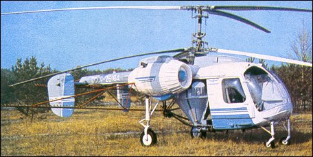
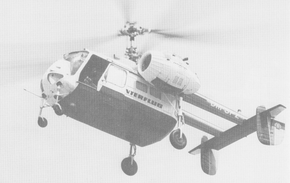
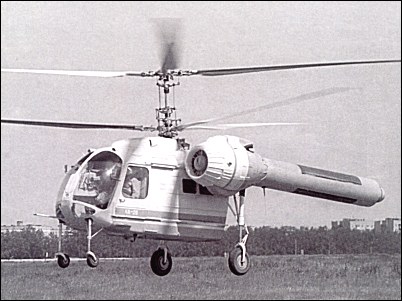
The Kamov Ka-26, which has the NATO codename Hoodlum, was announced in January 1964 as a light commercial helicopter with twin-turbine powerplant and a design easily convertible to meet the requirements of several roles. The primary task envisaged for the Ka-26 was agricultural.
The design team was headed by deputy chief designer M.A.Kupfer; Yu.I.Petrukhin was the leading designer and V.S.Dordan the leading engineer in charge of the flight tests. Kamov opted for its standard co-axial contra-rotating twin rotor configuration, powered by a pair of 325hp / 242.5kW Vedeneev M-14V-26 radial piston engines. To leave the area under the transmission and rotor assemblies free for the payload, the engines were installed in pods at the ends of shoulder-mounted stub wings, the engines and transmission being connected by drive shafts with flexible couplings.
The fuselage forward of the stub wings is a minimal pod with the crew cabin at the front, while the glassfibre tail unit is carried on twin booms and has conventional flying controls.
The greater weight of the piston engines units compared with turbines has been compensated by the use of lightweight materials in the airframe. In the Ka-26 helicopter the Kamov OKB made its first large-scale use of parts and subassemblies made from composite materials. Each of the interchangeable rotor blades is made of plastic, and weighs only 25kg; and much of the fuselage is made of aluminium panels sandwiched in glassfibre. Composite rotor blades had a 5000-hour service life.
The first prototype flew on August 18, 1965 flown by test pilot V.V.Gromov, followed by a small pre-series batch and the first production Ka-26 was flown during 1966. State trials were successfully completed in the autumn of 1967. Production was launched in the town of Kumertau at a factory which had been purpose-built in 1962. The Kumertau Aircraft Production Association continued production of helicopters bearing the Kamov emblem. The design leaves the area under the engines and on the centre of gravity free for the payload. For agricultural work a 900kg hopper can be fitted, the load being spread by spray-bars or dust-spreaders under the hopper and aft of the tail assembly. For passenger operations the Ka-26 can be fitted with a detachable pod for six passengers on tip-up seats, and for freight work this pod can be used to carry up to 700kg.
The fully enclosed cabin has with door on each side, and is fitted out normally for operation by single pilot with a second seat and dual controls optional. The cabin is warmed and demisted by air from a combustion heater, which also heats passenger compartment when fitted. An air filter is mounted on the nose of the agricultural version. A geophysical survey version carries a large hoop aerial around the fuselage, an electro-magnetic receiver bird (towed beneath the helicopter on a cable), and pulse generating equipment inside the cabin. As an air ambulance, the Ka-26 can carry two stretcher patients, two seated casualties and a medical attendant. A winch, with a capacity of up to 150kg, enables it to be used for search and rescue duties. Ka-26s used in this role in Russian coastal areas are each fitted with three large inflatable pontoons, to permit operation from water. During tests, the hoist has been used to tow boats in Sea State 5 conditions.
When operating as an agricultural sprayer, the Ka-26 originally discharged its chemical payload at 1.5-12 litres/s. The rate of discharge in a dusting role was 1.5-12kg/s. Up to 120 ha could be sprayed during each flying hour at the rate of 50kg/ha. As a duster, 140 ha could be treated at the same discharge rate. 50 ha could be top-dressed with chemical fertilisers each hour, at a rate of 100kg/ha. These work rates were improved substantially by the introduction of an atomiser for liquid chemicals in 1978, followed by a centrifugal spreader for granular chemicals and dust in 1979. To protect the pilot against toxic chemicals in the agricultural role, the cabin is lightly pressurised by a blower and air filter system.
The Ka-26 was the first Soviet helicopter to be certificated in accordance with US FAR 29 airworthiness regulations. It was also the first Soviet helicopter to be sold abroad on a commercial basis; the Ka-26 was exported to 17 foreign countries. For more than 30 years it has been doing its job with dignity. The total flying hours amassed by the type amount to 2,907,000 hours by 1982, and in 1980 and 1982 the Ka-26 established five world records.
Six Ka-26’s were ordered by an operator in Southern England in April 1967, the first order ever placed by a British customer for an aircraft designed and built in the USSR.
Rolls Royce and Kamov signed an agreement to provide five Rolls Royce RTM322 engines for the new KA 62R due to fly in 1993. The KA 62R was designed to carry some 14 passengers as a multi purpose utility aircraft.
The Ka-26SS was a no-tail-rotor (NOTAR) technology testbed. 816 Ka-26 were built between 1968 and 1977.
Ka-26 Engines: 2 x Vedeneev M 14V 26, 325 shp / 239kW. Rotor diameter: 42 ft 8 in (13.00 m) each. Fuselage length: 25 ft 5 in (7.75 m). Height: 4.05m Fuselage width: 3.64m Rotor disc area: 1,4287 sq.ft (132.73 sq.m). Weight empty: 4454.1 lb / 2020.0 kg Gross weight: 7,165 lb (3,250 kg). Max payload transport: 1985 lb / 900 kg Max payload ag duster: 2348 lb / 1065 kg Max payload ag sprayer: 1985 lb / 900 kg Max payload cargo platform: 2348 lb / 1065 kg Max payload crane: 2425 lb / 1100 kg Normal TOW transport: 6780 lb / 3076 kg Normal TOW ag: 6570 lb / 2980 kg Max speed: 160 kph. Max cruising speed: 93 mph / 81 kt / 150 kph Ag operating speed: 16-62 kt / 19-71 mph / 30-115 kph Service ceiling: 9840 ft / 3000 m Typical range: 250 miles / 400 km / 215 nm with 7 passengers / 30 min res. Max range aux fuel: 647 nm / 745 mi / 1200 km Accommodation: Crew of 1 or 2 and up to 7 passengers. Hopper capacity: 1985 lb / 900 kg Winch capacity: 330 lb / 150 kg Pax pod length: 6 ft 10 in / 1.83 m Pax pod width: 4 ft 1.25 in / 1.25 m Headroom: 4 ft 7 in / 1.40 m
KA 62R Engine: 2 x Rolls Royce RTM322 Pax cap: 14.
Originally from an urgent requirement placed in 1958, in the 1960s it became clear that from the Ka-20 helicopter Kamov’s bureau, under chief engineer Barshevsky, had developed the standard ship-based machine of the Soviet fleets, replacing the Mi-4. Designated Ka-25 and allotted the new Western code name of “Hormone”, it was in service in at least five major versions, with numerous sub-types, including the Hormone A (ship-based ASW), Hormone B (over-the-horizon-targetting) and Hormone C (SAR). The air to surface missiles carried by the Ka 20 demonstrator did not appear on the Ka 25. The most obvious external differences be¬tween Harp and Hormone are a strengthening of the undercarriage, with the addition of a second strut, and a slight redesign of the vertical tail surfaces.
For the first time, Kamov designers fitted a rotary-wing aircraft with a mission avionics suite and weapons system which allowed the helicopter to navigate above water surface devoid of any reference points and fulfill the task of locating and destroying a submarine, both in manual and automatic mode. During prototype construction the designers – for the first time in OKB history – had to adapt it to the ship. The Ka-25’s take-off weight increased 5-fold compared to that of the Ka-15 for an increase in dimensions by a factor of only 1.6. To reduce the rotor-craft’s dimensions for hangar stowage during cruise, the designers created an electromechanical rotor blade folding system. This made the helicopter quite compact with the overall length with the blades folded was only 11.0m.
Powered by two GTD-3F turboshaft engines developed by V.A.Glushenkov, the Ka-25 first flew in 1961 with test pilot D.K.Yefremov at the controls. The Ka-25 was shown in Soviet Aviation Day flypast, Tushino Airport, Moscow, July 1961, carrying two dummy Air-to-Surface Missiles (ASMs not fitted to production aircraft), entering active service in 1965. The engines are above the cabin and external mounting of operational equipment and auxiliary fuel leaves the interior uncluttered. Two 671kW Glushenkov GTD-3F turboshafts, mounted side by side above cabin, forward of rotor driveshaft, were on early aircraft and later aircraft have 738kW GTD-3BM turboshafts. There is independent fuel supply to each engine, and provision for carrying external fuel tanks on each side of cabin. Equipment includes an autopilot tailored to deck operations and hover, twin-gyro platform and Doppler, duplicated HF, VHF, UHF, night lighting plus strobe, radio compass, radar altimeter, IFF and four passive RWRs. Definitive Ka-25 prototypes incorporated anti-corrosion structure, cabin housing mission equipment. NII testing 1963-69. Rotors with lubricated hinges and aluminium blades with nitrogen-pressure crack warning, hydraulic control, alcohol deicing and auto blade folding. Forward-facing electrically heated inlets, lateral plain (no IR protection) exhausts, and rear drive to rotors and to large cooling fan for oil radiator served by circular aft-facing inlet above rear fuselage. Airframe entirely dural stressed-skin, mainly flush-riveted but incorporating some bonding and sandwich panels. Main fuselage devoted to payload; side-by-side dual control nose cockpit with sliding door on each side. Entry to main cabin is via a rearward-sliding door to rear of main landing gear on port side. The main cabin is 1.5m wide, 1.25m high and 3.95m long with sliding door on left and access at front to cockpit, and much of underfloor volume occupied by left right groups of tanks filled by left-side pressure connection. Cable fairing along right side of cabin. Short boom for tailplane with elevators and central fin and toed-in tip fins carrying rudders. Latter used mainly in autorotation, yaw control by pedals applying differential collective; mixer box holds total rotor thrust constant to reduce workload eg landing on pitching deck. Rotors not designed for negative-g. Two castoring front wheels (tyres 400×150) on vertical short strut with rear brace pivoted to fuselage to swing up and out to rear out of radar FOV. Two sprag-braked main wheels (600×180) each on vertical strut able to swing vertically on parallel V-struts pivoted to fuselage for same reason; landing loads reacted by diagonal shock retraction strut. Each wheel fitted for rapid-inflation buoyancy collar. The Ka-25’s flight test programme revealed that each type of warship had its peculiarities as far as pitching and rolling characteristics and airflow over the deck were concerned. Development of methods of helicopter landings on ships of different categories in daytime and at night with the ship under way and at rest, as well as water landing techniques, was accomplished by test pilots V.M.Yevdokimov and N.P.Bezdetnov. They conducted a large amount of test work with a view to evaluating the automatic engine control system, mastering single-engine piloting techniques and making engine-out landings in autorotation mode without a landing run.
The State acceptance trials of the Ka-25 were completed in 1968.
Ka-25Ts Hormone B
At its own initiative, the OKB made an attempt to build a civil derivative of the Ka-25 – the Ka-25K intended for cargo and passenger transportation and for flying crane operations. In 1967 the Ka-25K prototype was successfully demonstrated in the static display and in flight at the Le Bourget / Paris Air Show in 1967. It had an extensively glazed gondola under the nose (in place of the fairing for the search radar of the military version), with a rearward-facing operator’s cockpit suspended under the forward fuselage for controlling the machine during operations with slung loads. A hatch was provided in the cabin floor for a cable to be lowered by winch. The cabin could take either a maximum load of 2000kg, 12 passengers or four stretchers and an attendant. The engines, a pair of 900shp Glushenkov GTD-3 turboshafts, are mounted side-by- side forward of the transmission. Design work on the Ka-25K was led by deputy chief designer I.A.Ehrlikh; the leading designer was S.V.Mikheyev. Although intended primarily as a flying crane, the Ka-25K can also be used as a conventional transport helicopter. In this role the chin gondola is removed, and the load is accommodated in the large hold. The floor has nine lash-down points for freight, which can be loaded through a sliding door in the left side. Alternatively, up to 12 passengers can be carried on tip-up seats along the sides of the hold. This variant was not put into production or service.
Two versions of the helicopter were designed in parallel: the Ka-25PL and the Ka-25Ts. The former is a submarine hunter equipped with weapons, the latter is a reconnaissance platform tasked with seeking out surface targets and designating them to the powerful artillery and rockert weapons placed on ships and at coastal bases. The airframe, rotor system and powerplant of these helicopters were designed with a maximum degree of commonality.
The Ka-25PL was exported to India, Syria, Bulgaria, Vietnam and Yugoslavia.
The Ka-25Ts (“Hormone-B”) special electronics version provides over-the-horizon target acquisition for ship-launched cruise missiles including SS-N-3B (NATO “Shaddock”) from “Kresta I” cruisers, SS-N-12 (“Sandbox”) from “Kiev” and “Slava” class cruisers, SS-N-19 (“Shipwreck”) from battle cruisers Kirov and Frunze, and SS-N-22 (“Sunburn”) from “Sovremenny” class destroyers. “Kiev” and “Kirov” class ships each carry three “Hormone-Bs”, other classes one; larger undernose radome (NATO “Big Bulge”) than Ka-25BSh, with spherical undersurface; cylindrical radome under rear cabin for datalink; when radar operates, all landing gear wheels can retract upward to minimise interference to emissions; cylindrical fuel container each side of lower fuselage.
The four landing wheels are each surrounded by a buoyancy bag ring which can be swiftly inflated by the gas bottles just above it. The traditional Kamov layout with superimposed coaxial rotors redu¬ces disc diameter, and automatic blade folding is provided for stowage in small hangars. The four ¬legged landing gear is specially tailo¬red to operation from pitching decks, each leg having an optional quick-infl¬ating flotation bag. The rear legs can be raised vertically, on their pivoted bracing struts, to lift the wheels out of the vision of the search radar always fitted under the nose.
NATO recognises two distinct variants of the Ka-25, and two radars have been identif¬ied. The smaller type is carried by the Hormone A variant on ASW missions; this model also has a towed MAD bird, dipping sonar, electro optical sensor (and possibly others), and an optional right side box of sonobuoys. Basically a ship-based and antisubmarine version operating from cruisers of the Kresta and Kara classes, Moskva and Leningrad carrier/cruisers and Kiev and Minsk ASW cruisers. The Moskva and Leningrad carrier/cruisers can carry about 18 Ka-25s; the larger Kiev and Minsk, about 30. Those of the Kara class carry three and the Kresta four (Kresta I) or five (Kresta II). Some models have been seen with different types of fairings. Some have big hatches beneath the fuselage, enclosing a bay for antisubmarine torpedoes, nuclear depth charges or other types of weapons.
A larger radar is fitted to the Hormone¬-B for electronic countermeasures, which is believed to be able to guide the SS N 12 ‘Sandbox’ cruise missile fired from friendly surface ships and, especially, submarines. Many other equipment items include a cylindrical container under the rear of the cabin and a streamlined pod under the tail.
Hormone-A has a search radar in a large fairing under the nose, and a towed magnetic anomaly detector (MAD), while a dipping sonar is housed in a compartment at the rear of the cabin. The helicopter also has electro-optical sensors. The Hormone-B has no ventral loading doors.
The first ocean cruise of the Ka-25 took place in April-September 1967. The helicopter operated from the flight deck of the “Tobol” mothership, having logged 100 flight hours during the cruise. Deployment of helicopters on ships – both singly and in groups – was subjected to a very stringent testing on ships of various types, including the ASW cruisers “Moskva” and “Leningrad”. The Ka-25 ensured the navigation of ships in the Polar North, operating from the nuclear-powered icebreaker “Sibir”. At the time, this task could only be tackled by the Ka-25 fitted with modern avionics, including a 360 degree search radar.
In 1982 Ka 25s were seen with¬out flotation gear but with a long ventral box housing (it is believed) a long wire guided torpedo. All Ka 25s have a large cabin normally provided with 12 folding seats additional to those for the crew of two pilots plus three sys¬tems operators. About 460 of all variants were built by 1975, and the type continued to play an important part in Soviet naval operations in 1989, operat¬ing from destroyers, cruisers, helicop¬ter carriers (18 are believed to be car¬ried on each of the two ships Moskva and Leningrad) and aircraft carriers (Kiev and Minsk each accommodate 16 ‘Hormone A’ and three ‘Hormone B’ helicopters). Ka-25s were used aboard the Kresta and Kara class cruisers and from shore bases. The type has also been exported for ship and land based op¬erations.
The Hor¬mone C search and rescue helicopter is based on the ‘Hormone A’ without the latter’s mission equipment. The Ka-25C was utilised in vertical replenishment as well as search and rescue operations. In all, 18 different modifications of the Ka-25 were designed and built, including the Ka-25PL basic ASW version, the Ka-25Ts over-the-horizon (OTH) targeting version, the Ka-25PS SAR version, the Ka-25BT mine countermeasures version, the civil Ka-25K flying crane etc.
Versions of the Ka-25 were in service with the armed forces of India (5), Russian Federation (65), Syria (5), Ukraine (18), Vietnam (5), and Yugoslavia. 12 Soviet Navy Ka-25BTs took part in minesweeping operations in the Suez Gulf.
Total production 1966-75 about 460.
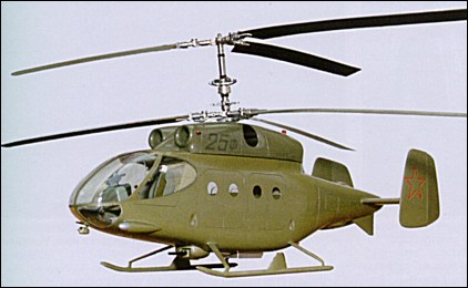
Ka-25F
As early as 1968, when N.I.Kamov was still alive, the OKB joined the competition of design studies for an Army assault/transport helicopter. The Kamov contender was a derivative of the Ka-25 designated Ka-25F featuring a redesigned fuselage and skid undercarriage. The armament comprised a 23-mm GSh-23 cannon with 400 rounds in a chin turret, six UB-16-57 rocket pods with 57-mm unguided rockets, six “Falanga” (Solifuge) anti-tank guided missiles, and bombs. The Ka-25F project received a positive appraisal from the Air Force’s research institutes but lost out to the competing Mi-24 helicopter.
Versions:
Ka-25B (“Hormone-A”) Ship-based anti-submarine helicopter, operated from former Soviet Navy missile frigates, cruisers, helicopter carriers and carrier/cruisers of “Kiev” class; major shortcoming is lack of automatic hover capability, preventing night and adverse weather use of dipping sonar. Replaced progressively by Ka-27PL (“Helix-A”).
Ka-25BSh ASW version. I/J-band search radar with 360 degree scan in flat-bottom radome under nose, box for three vertical sonobuoys can be clipped aft on right side. Oka-2 dipping sonar at aft end of fuselage on centerline or (seldom fitted) APM-60 MAD sensor in pod on pylon under tail, large ESM receiver drum above boom with optional ADF sense blister immediately to rear, EO viewing port under boom, upgraded EW suite. Weapon bay 0.9m wide under centerline, initially with two bulged doors, later as largely external rectangular box, tailored mainly to two AS torpedoes (originally 450mm calibre) with wire reel on left side of fuselage; alternatively nuclear or conventional depth charges or other stores, max 1.9t. Replaced in CIS Navy by Ka-27PL, but serves with India, former Yugoslavia, Syria and Vietnam. ASCC “Hormone-A”.
Ka-25BShZ Equipped to tow minesweeping gear.
Ka-25PL Version developed to replace Ka-25B as ship-based anti-submarine helicopter.
Ka-25PS (“Hormone-C”) Search and rescue version with special role equipment, including hoist. No weapon bay, radar as BSh, normal equipment includes winch, 12 seats, provision for stretchers and aux tanks; options include nose quad Yagi antenna for homing receiver, ESM, searchlight and loudspeaker. Replaced by Ka-27PS.
Ka-25Ts (“Hormone-B”) Special electronics version, providing over-the-horizon target acquisition for ship-launched cruise missiles. ASW and ESM equipment and weapon bay omitted, internal fuel increased, OTH targeting and cruise-missile guidance radar with large elliptical (instead of rectangular) scanner reflector in bulged radome, secure data link to surface fleet including small antenna in vertical cylinder under rear centerline of fuselage.
Ka-25K Single civil prototype (SSSR-21110) 1966 with gondola under lengthened nose for controlling 2t slung load; elec-deiced blades, option 12 passenger seats. No ASCC name.
Specifications:
Engines: 2 x Glushenkov GTD-3F turboshaft, 662kW / 900-shp Rotor diameter: 15.74m / 51.64 ft Fuselage length: 9.75m / 32 ft Fuselage width: 12.35 ft Height: 5.37 m / 17.61 ft Max take-off weight: 7100kg / 16,500 lb Empty weight: 4100kg Max speed: 220km/h / 113 kts Cruising speed: 200km/h Service ceiling: 3500m / 11,500 ft Range: 400km / 217 nm Internal payload: 1500kg External payload: 2000kg Crew: 1-2
Engines: 2 x Glushenkov GTD-313M free-turbine turboshaft, 900 hp. Main rotor diameter (both) 51 ft 8 in (15.75 m) Fuselage length, about 34 ft (10.36 m) Height 17 ft 8 in (5.4 m) EmptyWeight: about 11,023 lb (5000 kg) Maxi¬mum loaded weight 16,535 lb (7500 kg) Maximum speed 120 mph (193 kph) Service ceiling, about 11 000 ft (3350 m) Range with exter¬nal tanks 650 km (405 miles) Armament: one or two 400 mm AS torpedoes nuclear or other stores, internal.
Engines: 2 x GTD-3F turboshaft, 728kW Rotor diameter: 15.74m Fuselage length: 9.75m Height: 5.37m Max take-off weight: 7200kg Empty weight: 4765kg Max speed: 220km/h Cruising speed: 180km/h Service ceiling: 3500m Range: 450km Crew: 2-3
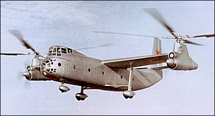
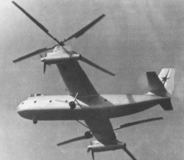
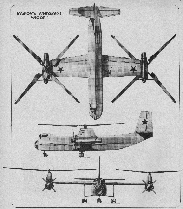
In 1951 various attempts were being made to increase the effective range of helicopters, notably by towing them in the outward direction behind an Li-2, with the lifting rotor autorotating. The idea occurred to Kamov designer Vladimir Barshevsky that it would be possible to dispense with the tug aircraft if a helicopter could be provided with wings and an aeroplane propulsive system. After obtaining permission from Kamov, his deputy V. V. Nikitin took a proposal to the Kremlin and in a matter of days the OKB had a Stalin directive to get started. In response to the GOR issued by the Ministry of Defence, Kamov decided to build an experimental compound helicopter, the Ka-22. Dubbed “Vintokryl” (lit. “screw-wing”), it featured two lifting rotors and two tractor propellers for forward thrust, both mounted at the wingtips. This was an aircraft, combining the advantages of the helicopter capable of vertical take-off and landing and of the aeroplane possessing greater lifting capacity, range and speed as compared to the helicopter. N.I.Kamov focused the attention of the team on the design of high-speed lifting rotors which would enable the compound aircraft to cruise at 400-450km/h. At high forward speeds the wing was intended to decrease rotor disc loading as much as possible, ensuring low drag factors. This allowed the tips of the main rotor blades to reach the speed of sound and the rotor to work in a mode close to autorotation. N.I.Kamov’s decision to retain minimum required rotor disc loading at high speed sufficient for damping rotor oscillations and for ensuring stable rotor behaviour during manoeuvers proved to be of fundamental importance.
The engines were to be TV-2 (later TV-2VK) turboshafts supplied by N. D. Kuznetsov, and many organizations were involved in research for this challenging project, starting with model tests in the T-101 tunnel at CAHI. The final go-ahead was issued on 11th June 1954. An order for three Ka-22s was placed on the factory at Ukhtomskaya, which had been derelict since Kamov was evacuated from there in October 1941. Concentration on the small Ka-15 (the OKB’s first production helicopter) and other problems so delayed the programme that on 28th March 1956 prototypes 2 and 3 were cancelled.
Development and construction of the Ka-22, project 1955, under the leadership of S.Ya.Finkel, developed a whole set of methods to determine the aircraft’s parameters, rotor blade configuration, basic performance characteristics of the rotorcraft and its aerodynamic design, to calculate aerodynamic loads, aerodynamic balancing etc. Special research was made to ensure optimum characteristics in transitional flight modes, to select structural stiffness characteristics of the airframe components, to prevent rotor blade flutter and “ground resonance”. A major contribution to the creation of the Ka-22 was made by S.B.Garshtein, AI.Dreizin, Z.Z.Rosenbaum, A.G.Satarov, E.A.Petrosian, L.A.Potashnik, V.N.Kvokov and other members of the OKB staff, as well as by TsAGI specialists M.K.Speransky, I.O.Faktorovich and E.V.Tokarev.
Work on the unique powerplant and systems of the aircraft was headed by deputy chief designer N.N.Priorov, and deputy chief designer M.A.Kupfer was responsible for the rotor system and the airframe. Yu.S.Braginsky was appointed Ka-22 leading designer and V.B.Al’perovich was the leading engineer of the flight test programme. First deputy chief designer V.I.Biryulin was responsible for all the work on the compound helicopter.
The Ka-22 was basically a stressed-skin compound helicopter with its engines on the wingtips, with geared drives to both propellers and lifting rotors. The airframe was all light alloy stressed-skin, the high wing having powered ailerons and plain flaps depressed 90° in helo mode, with auto control linking fuel flow with prop pitch in cruise. The fuselage had a glazed nose, three-seat cockpit above the nose and a main cargo area 17.9×3.1×2.8m for 80 seats or 16.5 tonnes of cargo. The entire glazed nose could swing open to starboard for loading bulky items or a vehicle. The high flight deck carried two pilots and a radio engineer. The original prototype was powered by 5,900shp TV-2VK engines, but these were later replaced by the 5,500shp D-25VK. These had free turbines geared via a clutch to the main rotor and via a front drive to the four-blade propeller and a fan blowing air through the oil cooler from a circular inlet above the nacelle. The two free-turbine outputs were interconnected by a 12-part high-speed shaft ‘about 20m long’. The propulsion system, in the form of a pair of 5600 horsepower Ivchenko turbine engines, provided the propulsive force for both the lifting flat-mounted rotors and the normally-positioned forward-pushing propellers. The tailpipes of these powerplants are assessed to have tail pipes that can be deflected downward to provide additional lift during the vertical flight phase of the trajectory. The main rotors were larger derivatives of those of the Mi-4. In helicopter mode the propeller drive was declutched and the flaps were fully lowered. Flight control was by differential cyclic and collective pitch. In aeroplane mode the lifting rotors were free to windmill and the aircraft was controlled by the ailerons and tail surfaces. The twin-wheel landing gears were fixed. A conventional aeroplane tail was used only in aeroplane mode.
The engine normally has a rear drive from a free turbine, and the installation has a rear jetpipe and air from inlet ducted round underside of cowling, driving at rear to high-speed shaft to reduction gearbox under rotor shaft, from which front drive goes to propeller. Upper circular inlet feeds fan-assisted oil cooler. Superficially rotors and hubs resembled those of Mi-4 and Yak-24, but with trailing-edge tabs inboard; handed, left rotor being clockwise seen from above.
In June 1958 the LD-24 rotor blades began testing on an Mi-4. The Ka-22 itself first lifted from the ground on 17th June 1959, and made its first untethered flight on 15th August 1959, the test crew being led by pilot D. K. Yefremov. Serious control difficulties were encountered, and the Kamov team were joined by LII pilots V.V.Vinitskii and Yu.A.Garnayev. Though still full of problems the Vintokryl was demonstrated on 11th October 1959 to MAP Minister P.V.Dement’yev and VVS C-in-C K.A.Vershinin. Gradually difficulties were solved and in July 1960 an order was received to manufacture three Ka-22s at GAZ No.84 at Tashkent, with D-25VK engines.
On 23rd May 1961 a speed of 230km/h was held for 37 minutes. On 9th July 1961 the Ka-22 caused a sensation at the Aviation Day at Tushino.
In 1961 an OKB test crew captained by D.K.Yefremov, assisted by V.V.Gromov, set eight world records on the Ka-22, including the world helicopter speed record and the payload to 2000m altitude record. On 7th October 1961, with spats over the wheels and a fairing behind the cockpit, a class speed record was set at 356.3km/h, followed on 12th October by 336.76km/h round a 100km circuit. The spats and fairing were then removed and on 24th November 1961 a payload of 16,485kg was lifted to 2,557m. OKB testing was completed early 1964. The compound helicopter was impressive by any standards: maximum take-off weight was 42500kg; the cargo cabin was 17.9m long, 2.8m high and 3.1m wide. To compare the maximum take-off weight of the then biggest Kamov helicopter, the Ka-25, was 7000kg.
Preparations were then made to ferry AM 0I-01 and the third machine AM 0I-03 from Tashkent to Moscow for Nil acceptance testing. Both departed on 28th August 1962. While making an intermediate stop at Dzhusaly 0I-01 rolled to the left and crashed inverted, killing Yefremov and his crew of six. The cause was diagnosed as ‘disconnection of No 24 cable joint of the linkage with the starboard lift rotor collective-pitch control unit’. At Tashkent and in Turkestan the cable joints and cyclic-pitch booster brackets were inspected on 0I-02 and 0I-03 and found to be incorrectly assembled. Changing the direction of rotation of one lifting rotor did little at lower speeds and caused problems at higher speeds – ‘When’, said lead engineer V.S.Dordan, ‘Shockwaves off the blades sounded like a large machine gun’. To improve stability and controllability the complex AP-116 differential autopilot was installed, continuously sensing attitude and angular accelerations, feeding the KAU-60A combined flight-control unit. On 12th August 1964 the heavily instrumented 0I-03 took off on one of a series of tests conducted with VVS (air force) and GVF (civil) crews. Take-off was in aeroplane mode, and 15 minutes later at 310km/h the aircraft suddenly turned to the right, ‘not arrested by full rudder and aileron…the aircraft turned almost 180° when Garnayev intervened, considering the problem was differential pitch of the propellers… turn rate slowed, but the aircraft pitched into a steep dive…the engineer jettisoned the flight-deck hatches, and one struck the starboard lift rotor causing asymmetric forces which resulted in separation of the entire starboard nacelle. Garnayev ordered the crew to abandon the aircraft’. Three survived, but Col S.G.Brovtsev, who was flying, and technician A.F.Rogov, were killed. By this time the Mi-6 heavy helicopter was in wide service, and the Ka-22 was ultimately abandoned. Several years later the two surviving machines, 0I-02 and 0I-04, were scrapped. An article about the Ka-22 in Kryl’ya Rodiny (Wings of the Motherland) for November 1992 does not mention the fact that two crashed.
Ka-22 Crew: 5 Engines: 2 x D-25VK turboshaft, 4050kW Rotor diameter: 22.5m Fuselage length: 27m Height: 2.8m Max take-off weight: 42500kg Payload: 16500kg Max speed: 356km/h Service ceiling: 5500m Range: 450km
To meet a Soviet Naval Air Force specification in the late fifties for an antisubmarine helicopter for ship or shore-based use, the Kamov bureau developed a helicopter powered by twin turbines installed side-by-side above the cabin, with two three-bladed coaxial, contra-rotating rotors as on their other aircraft. It was first seen at the Tushino air display in July 1961 and was assigned the NATO reporting name Harp.
The Harp was characterized by a large radome under the nose and a fairing beneath the tail boom. The armament consisted of two fixed machine guns in the nose and two small missiles at the sides of the fuselage.
The Ka 20 was later developed as the Ka 25 shipboard and shore-based antisubmarine helicopter. Despite the small number of changes made in the transition from prototype to production standard, the reporting name Harp was not continued, the Ka 25 being allocated the name Hormone.
Rotor diameter: 15.74 m (51ft 8 in) Length: 9.83 m (32ft 3 in) Weight: 7300 kg (16 100 lb) Powerplant: 2900 shp Glushenkov GTD 3 turboshafts Range: 400 km (250 miles) Maximum speed: 220 km/h (137 mph)
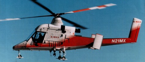
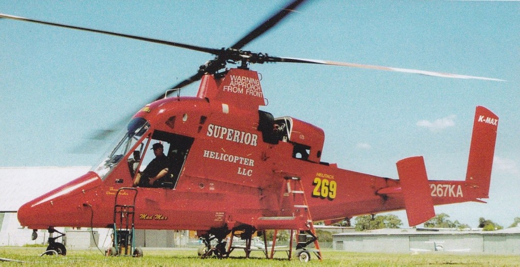
By July 1997, 23 K-Max had been built. Overall, the fleet had accumulated 26,000 hrs, with the highest time example reaching 4000 hr since delivery in October 1994. The production rate was six per year.
Kaman K-Max Engine: Textron Lycoming T 5317 A1, 1479 shp Instant pwr: 1118 kW. Length: 51.837 ft / 15.8 m Height: 13.583 ft / 4.14 m Rotor diameter: 48.228 ft / 14.7 m Max take off weight: 11501.3 lb / 5216.0 kg Weight empty: 4701.1 lb / 2132.0 kg Payload: 2722 kg Max. speed: 100 kts / 185 kph Max cruise: 100 kts Service ceiling: 25000 ft / 7620 m Crew: 1 Payload: max 2700kg ext.
The basic Seasprite design won a US Navy design competition during 1956 for a high performance, all-weather, multi-role utility helicopter, then designated the HU2K-1. The prototype Seasprite first flew on July 2, 1959 and an initial contract was for four prototypes and twelve production Kaman helicopters, now known as the UH-2A and given the name Seasprite. The initial production UH-2A models were powered by one engine, however, they were equipped for IFR operations and a total of 88 were ultimately built. The UH-2B was VFR equipped and 102 in total were built with fully retractable forward mounted main landing gears.
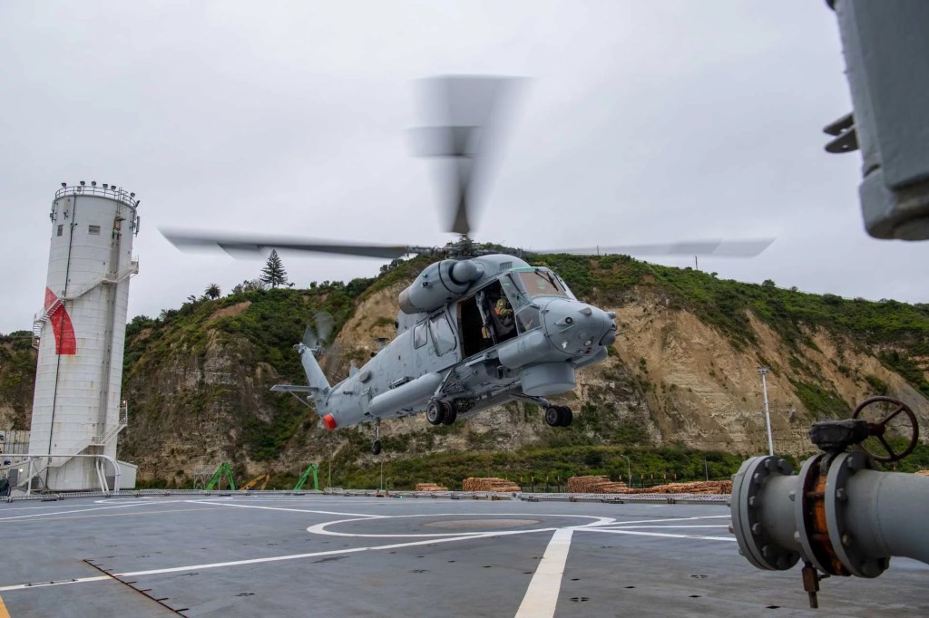
The UH-2A and UH-2B could each carry a 1814 kg (4,000 1b) slung load or 11 passengers, and work in planeguard, SAR, fleet reconnaissance, vertrep (vertical replenishment) and utility transport duties, operating from many surface warships as well as at shore bases. The UH-2C, a re-definition of the UH¬2 and UH-2B, was the first to be fitted with two engines. From 1967 Kaman converted of 88 earlier SH-2D Seasprites to the SH-2F version in May 1973. The SH¬2F “Super Seasprite” has “up-rated” engines and the LAMPS system (light airborne multi¬purpose system). Fifty-two new SH-2Fs were delivered from 1981. Deliveries of the SH-2F version began in May 1973 after completion of 190 early-model UH-2A/B SAR helicopters. Before manufacture was suspended 88 SH-2Fs were built. Deliveries from resumed production began in 1983, and Seasprites delivered after October 1985 have an increased gross weight of 6,124kg, compared with the 5,805kg of earlier SH-2Fs. With a crew comprising pilot, co pilot and sensor operator, the SH 2F can carry MASW gear including Canadian Marconi LN 66HP surveillance radar, towed ‘bird’ for the AN/ASQ 18 MAD, AN/ALR 64 passive detection receiver, Difar passive and Dicass active sonobuoys, and comprehensive nav/com and display systems. The 4,000 1b (1814 kg) cargo ability remains, and a 600 1b (272 kg) rescue hoist is standard. Production of the twin-turbine SH-2F Seasprite Mk.1 light airborne multipurpose system (Lamps I) restarted in 1982, to meet a US Navy requirement for up to 60 helicopters to equip vessels too small for the SH-60B Seahawk. Up to FY1986 54 new-build SH-2Fs had been authorised, and six more were requested in FY1987. These will join some 79 SH-2Fs from earlier production which were still in service at the beginning of 1986, some of which were upgraded SH-2Ds. Ten new SH-2Fs were delivered in 1986. A re-engined version of the Seasprite, the YSH-2G, flew on April 2, 1985, powered by two General Electric T700 turboshafts similar to those used in the SH-60B and giving improved range, reliability, and maintainability. Evaluation of the prototype YSH-2G was completed in 1985. In general terms, the SH-2G is a retrofit of the SH-2F model. The heart of the SH-2G(NZ)’s weapons platform is its Litton ASN-150/1553B tactical data system, APS-143 (V) 3 radar, Doppler APN-217 (V) 6 radar, FUR Systems AAQ-22 forward-looking infrared system, and Litton Amecon LR-100 electronic support measures ESM sensor system. These systems are operated from the two pilot analogue cockpit, with the observer (air¬borne warfare officer) occupying the left-hand seat. The helicopter’s missions are primarily surface sur¬veillance and anti-surface warfare, where the helicopter will conduct surveillance tracking and targeting and, if necessary, engage surface targets, but it is also capable of sub-surface weapon delivery and utility support, including search and rescue, replenishment, medical evacuation, naval gunfire spotting and troop transport for boarding operations.
SH-2G(A) Super Seasprite
In May 2006 the Royal Australian Navy’s fleet of 11 SH-2G(A) Super Seasprite was grounded with problems with their avionics and electronics systems. Service entry had been delayed by five years due to serious systems integration and software problems.
H-2 experiments included stub wings serving as sponsons and gunship version with Minigun chin turret among other weapons.
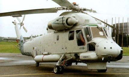
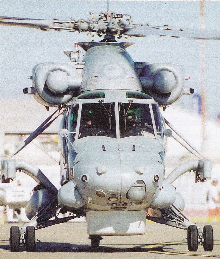
Kaman Aerosystems, are powered by two General Electric T700 turbines rated at 1,600 hp each. Measuring 16 meters in overall length with a 13.5-meter rotor diameter, they have a maximum take-off weight of 6,441 kg, a range of approximately 275 nautical miles, and a maximum endurance of around two hours and 45 minutes. Capable of reaching airspeeds near 130 KCAS, they feature a standard crew of three: a pilot, an observer responsible for warfare and mission coordination, and a helicopter loadmaster managing utility operations. Armament options include Penguin anti-ship missiles, Mk 46 torpedoes, and a door-mounted MAG 58 machine gun.
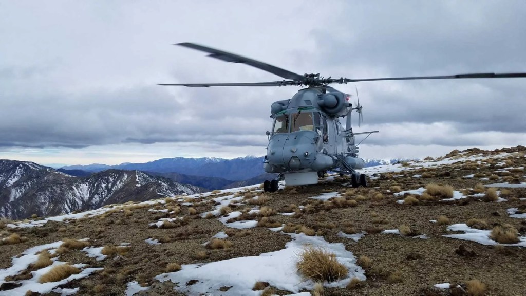
The SH-2G lineage traces its origins to the United States, where the type was developed in the 1980s as a modernized version of the SH-2F for use on naval vessels unable to accommodate larger helicopters like the SH-60B Seahawk. The SH-2G introduced more powerful engines, a reinforced upper fuselage, and improved avionics, including an Integrated Tactical Avionics System (ITAS) and digital automatic flight controls. Despite its eventual phaseout in the U.S. by 2001, the type continued to serve internationally, including with the Egyptian, Polish, and Peruvian navies.
The SH-2G(I)’s design emphasizes multi-role capability, supporting missions such as over-the-horizon surveillance using radar and FLIR systems, anti-ship strike with guided missiles, underwater warfare with torpedoes, as well as disaster response, medevac, and transport operations.
HH-2D Engines: 2 x General Electric T58 GE 8F turboshafts, 1,350 hp each. Length: 38 ft 4 in. Rotor dia: 44 ft. Speed: 168 mph. Ceiling: 22,500 ft. Range: 445 miles.
SH-2F Seasprite Engine: 2 x GE T58 8F turboshafts, 1,350 shp (1007 kW). Installed pwr: 2041 kW. Rotor dia: 13.4 m (44 ft 0 in). Main rotor disc area 141.25 sq.m (1,521.0 sq ft). Fuselage length: 12.3 m (40 ft 6 in), (folded): 11.7 m. Height: 4.72 m (15 ft 6 in). No. Blades: 4. Empty wt: 3193 kg (7,040 lb). MTOW: 6033 kg (13,300 lb). Max speed: 265 km/h (165 mph). ROC: 744 m/min. Ceiling: 6860 m. HIGE: 5670 m. HOGE: 4695 m. Fuel cap (+aux): 1500 lt ( 455 lt ). Range max¬ internal fuel: 680 km (422 miles). Crew: 3. Armament: one or two AS torpedoes (usually Mk 46).
SH-2G Super Seasprite Engine: 2 x GE T700-401. Instant pwr: 1259 kW. Rotor dia: 13.41 m. MTOW: 6124 kg. Payload: 2107 kg. Useful load: 987 kg. Max speed: 141 kts. Max cruise: 136 kts. Max range: 869 km. HIGE: 17,600 ft. HOGE: 14,600 ft. Service ceiling: 20,400 ft. Crew: 3. Pax: 8.
SH-2G(NZ) Engines: 2 x T700 GE-401 gas turbines of up to 1723 shp each, plus one Garret GTCP36-150 APU.
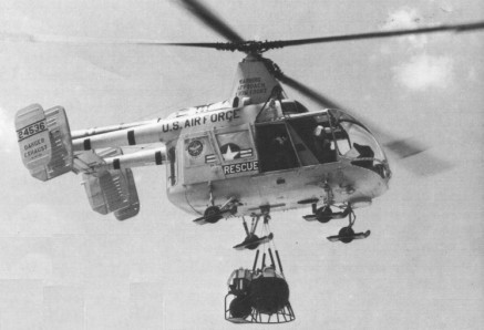
The H-43 was designed extremely compact because it’s inter-meshing rotors. Between 1958 and 1965 some 365 were built.
By late 1960s well over 200 H-43 Huskie turbine-powered rescue helicopters were serving with the USAF.
Kaman HH 43 B Husky Engine: Lycoming T53-L-1B, 848 shp Length: 25.164 ft / 7.67 m Height: 12.598 ft / 3.84 m Rotor diameter: 47.014 ft / 14.33 m Max take off weight: 9161.8 lb / 4155.0 kg Max. speed: 104 kts / 193 kph Service ceiling: 25000 ft / 7620 m Range: 240 nm / 445 km Crew: 1+8
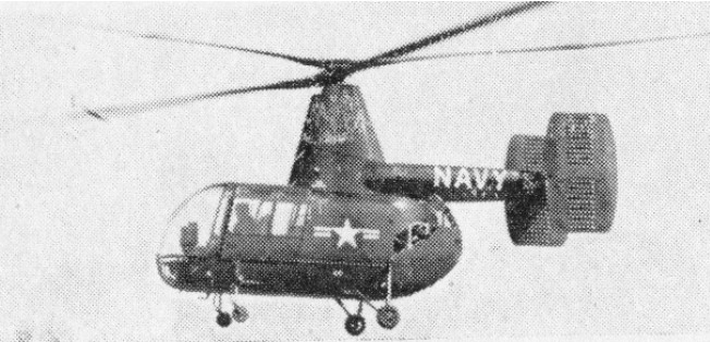
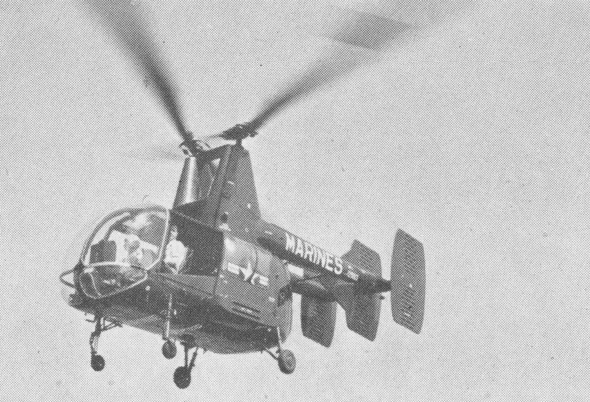
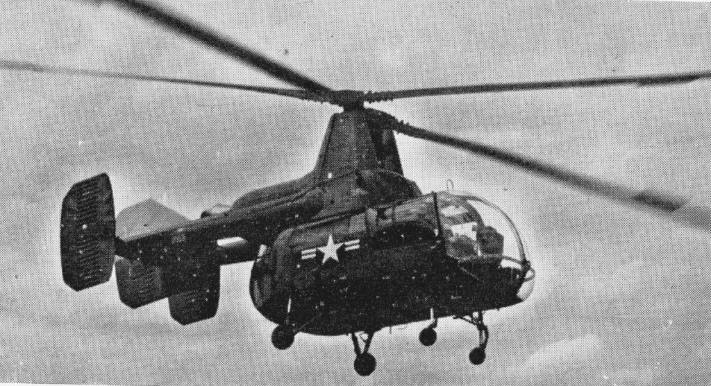
Following evaluation of the Kaman K-225, the US Navy chose the HOK-1 design as best of several submitted in competition for a liaison helicopter. Using the same rotor systems as the K-225, the HOK-1 was put into production off the drawing-board and delivered in quantity to the U.S. Navy and Marines during 1950s. It normally carries four people; but as an ambulance will accommodate two stretcher patients and one sitting patient or medical orderly, in addition to the pilot. Stretcher loading is through the nose, as on the HTK-1.
In service with the U.S. Navy in 1955 as a 4-seat liaison and casualty evacuation helicopter.
As part of a general development programme, several piston-engined helicopters, such as this Kaman HOK-1, were re-engined with gas turbines.
Engine: 800 hp Pratt & Whitney R1340-48 Rotor dia.: 46 ft. Max Weight: 3,500 lb. Seats: 4