(Emergency Fighter Program) in the middle of 1944. The Messerschmitt A.G.’s P.1104 was in the running. Heinkel won the contract.
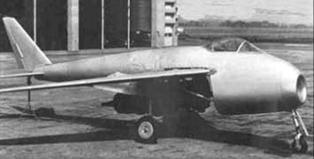
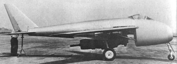
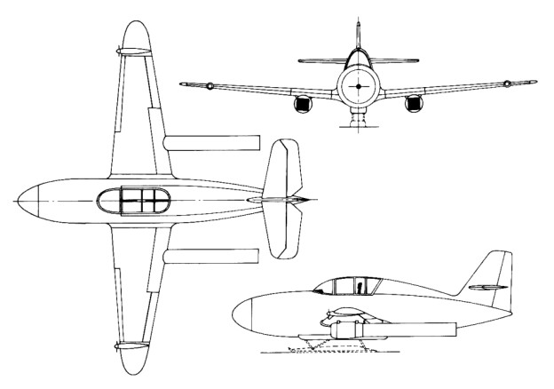
After two initial Messerschmitt designs were penciled, a finalized third design proposal was selected for development. The P.1101 was to have a deep fuselage to make room for the engine, applicable ductwork, the cockpit pressurization equipment, cannon armament and internal fuel. The fuselage would feature a nose-mounted intake to aspirate the Heinkel-Hirth He S 011 turbojet engine to be installed and wings were to be shoulder mounted assemblies with noticeable sweep. The single-seat cockpit would be fitted well ahead in the fuselage under a three-piece bubble canopy and a retractable tricycle undercarriage was utilized – the main landing gear legs coming from a Messerschmitt BF 109K fighter. The tail section was to be of a conventional type with a single vertical tail fin and applicable horizontal planes all made of wood. The tail assembly was fitted onto a tapered boom formed atop the engine exhaust port. Plans were made for cockpit armoring, carriage of four wire-guided missiles and a recessed centerline fuselage position for a single bomb.
To help speed development of the P.1101 along, it was decided to construct the P.1101 V1 prototype alongside the wind tunnel and other data collection still ongoing. The P.1101 V1 design was also given wings that would adjust their sweep preflight and could test wing sweep at 35- and 45-degree angles. The wings were eventually set to test sweep at positions of 35-, 40- and 45-degrees. changes to the wing sweep were to be made while the aircraft was still on the ground. First flight was slated for sometime in June 1945 if all went as planned. All development and construction was to take place at the largely unknown Messerschmitt facility at Oberammergau in the Bavarian mountains of Southern Germany.
For fear of the P.1101 data falling into enemy hands, Messerschmitt employees moved the information into microfilm form and hid them in four locations at neighboring villages. The Allies moved into the area on April 29th, 1945 with the Americans taking Oberammergau. The Me P.1101 V1 prototype was found in a tunnel and secured by the Americans. It was only later that Messerschmitt employees revealed the missing data and their locations. However, by this time, the French Army had moved in and found the hidden P.1101 data, subsequently shipping them back to French authorities. A joint American-German effort led by Robert Woods of Bell Aircraft and Woldermar Voight of Messerschmitt to secure the microfilm and finish the P.1101 fell on deaf ears – the French maintained little interest.
The P.1101 made its way to the US. Not only had exposure to the elements take their toll on the P.1011 airframe, the P.1101 airframe prototype fell off of her transporting railcar sustaining enough damage that ensured the V1 prototype would never be able to fly. Nevertheless, Bell Aircraft proceeded to break down the P.1101 and fitted the V1 with mock cannon armament along her fuselage sides and an American Allison J35 turbojet engine. The P.1101 V1 still served in valuable static ground tests before being scraped sometime in the 1950s.
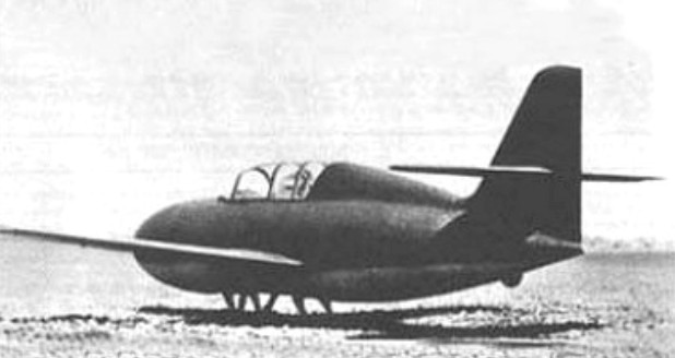
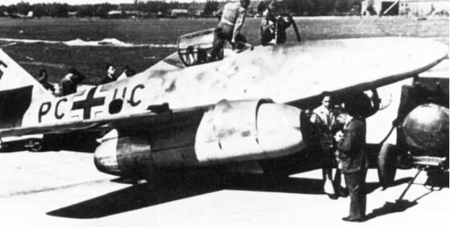
The Messerschmitt Me 328 was conceived in 1942 as a cheap and simple high-speed low-level bomber and emergency fighter. Smaller than the He 162, its construction was to be mainly of wood and power was to be provided by a pair of Argus pulsejet engines, similar to those used by the V-l flying bomb.
Two versions were proposed, the Me 328A fighter and Me 328B bomber. The single seat Me 328B was able to carry an under slung 1000 kg (2,205 1b) bomb, which reduced the speed at low level from 700 to 530 km/h (435 to 329 mph).
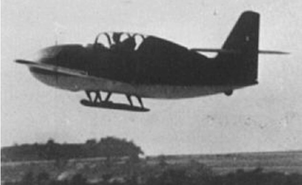
Powered by two Argus pulsejets, the Messerschmitt Me 328B 1 was designed as a fighter bomber armed with two 20 mm cannon and 1000 kg (2,205 lb) external load. The Me 328 started life as an escort fighter to be towed behind a He 177 or Me 264 bomber and as such the prototype underwent extensive gliding trials being air-launched from a Dornier 217.
Powered trials in 1944 proved disappointing. A further version, the Me 328C, was proposed, to be fitted with a Jumo 004 turbojet. This and a proposed piloted glider-bomb version did not eventuate.
Engines: 2 x 600kg Argus pulse-jets Max take-off weight: 2200 kg / 4850 lb Wingspan: 6.40 m / 20 ft 12 in Length: 6.83 m / 22 ft 5 in Height: 2.10 m / 6 ft 11 in Max. speed: 755 km/h / 469 mph Range: 770 km / 478 miles Armament: 2 x 20mm cannon
Messerschmitt’s P.1065 design had originated as early as 1938 when the Reichsluftfahrtministerium had requested the company to design a twin-engined fighter able to utilise the new turbojet engines being developed in Germany. After inspection of the mock-up, three prototypes were ordered on 1 June 1940.
It was initially designed around the Axial Flow BMW003 turbojet. In the axial flow turbojet air is compressed after entering the front of the engine by a series of compressor stages or fans, in the middle of the engine fuel is added and the mixture ignites, the rapidly expanding gases then pass through a turbine connected to the forward compressor stages before exiting the jet pipe. The design has the advantage of having a much smaller cross-section although it does suffer much more if debris are ingested into the engine.
There was a great deal of doubt over how much power the BMW engine would produce, estimates of less than 2,000lbs of thrust forced the designers to a twin-engine configuration as the only way to produce an aircraft capable of sufficient performance while carrying a useful warload. The smaller diameter of the engine however made it possible to suspend the engines below the wings without requiring excessively long main undercarriage legs to achieve ground clearance.
The construction of the first prototype ME262 V1 began in January 1941 and it was ready for flight long before its turbojet engines, early bench tests of these were very disappointing at just 570lbs of thrust, far too low for practical use. This led to the first prototype V1 being fitted with a conventional 750hp Jumo 210A in the nose driving a wooden propellor in order to flight test the airframe. It was ready for taxi trials on the 17th April 1941 and flew for the first time on the 18th April fitted with a tail wheel rather than the tricycle undercarriage that would be a feature of the later design.
The aircraft flew a total of 23 times on piston engine power up until 8th May 1941 when it finally received its pre-production BMW003 engines. The engines were rated at 1085lbs but the first flight was a disaster with both units failing, it was only saved from total loss by the by its piston engine and propeller which allowed a safe landing. The ME262 would not fly again with BMW engines until October 1943 when it was fitted with redesigned BMW003a engines. A small reciprocating engine is used for starting.
Of conventional all-metal stressed-skin construction, the wing had moderate sweepback, long-span ailerons, trailing-edge flaps, and full-span automatic leading-edge slots. The engines were mounted beneath the wing to preclude a complex wing-spar structure and the landing gear was of retractable tailwheel type. The fifth prototype introduced a non-retractable nosewheel unit and the sixth was the first to have a fully retractable tricycle-type landing gear necessitating the main undercarriage to be moved back 3ft in the wing.
Standard fuel for the Jumo jet is a brown coal oil known as J-2 and distinguished by a particularly disagreeable odor. Diesel oil and aviation gasoline may also be used but the latter is not considered practicable due to an extremely high rate of consumption.
The second and third prototypes V2 & V3 were modified to take the Jumo 004, this required a nacelle 10% larger in diameter and 16% longer. To counteract this the horizontal stabilizer was enlarged and the wings were swept back. V3 was the first to fly on the 18th July 1942 (piloted by Fritz Wendel) at Leipheim near Günzburg, Germany, with Jumo 004AA0 engines of 1,850 lbs thrust, V2 was completed in July 1941 but did not fly until 1st October 1942. The development program was expanded during this time to include two further prototypes and fifteen pre-production aircraft. The last two prototypes V4 & V5 flew on the 15th May 1943 & 26th June respectively.
In April 1941, Willy Messerschmitt actually proposed to fit a 35° swept wing (Pfeilflügel II) to the Me 262. Though this suggestion wasn’t implemented, he continued this line of thought with the projected HG II and HG III high-speed derivatives of the Me 262 in 1944, which were designed with a 35° and 45° wing sweep respectively.
ME262 V1 first flew again on jet power alone on the 20th March 1943 with Jumo 004A-0 engines, the piston engine had been removed and replaced with 3 x 30mm cannon and a partially pressurized cockpit added. It completed 65 flights up until the 7th July 1944 when it suffered a catastrophic engine failure; it was damaged beyond repair in the subsequent forced landing.
Five of the fifteen pre-production aircraft were allocated versuchs numbers to replace prototypes that had been lost or damaged and to expand the test program. The first of these 130001 V1+AA flew on the 17th October 1943 powered by Jumo 004B-0 engines. These weighed 220lbs less than the 004A while still delivering 1,980 lbs thrust. The aircraft also included fully retractable tricycle undercarriage. The aircraft completed a total of 28 flights until it crashed on the 9th March 1944 in a fatal accident.
The most significant impact on the development of the ME262 was the inability of Junkers (and BMW before them) to produce state of the art engines without the proper materials. This is demonstrated when considering the combustion chambers of the Jumo 004 which were made of ordinary steel sprayed with aluminium for heat resistance which led to frequent engine failures. The compression flow was also unstable at moderate speeds in addition to issues with fuel flow regulation which limited the effectiveness of the aircraft and resulted in an average engine life of around 20 hours.
Me 262A-2a
Armament for the 262 was to have consisted of two 55-mm cannon, but these, though designed, were not yet in production. Hitler then favored the installation of 50-mm tank guns but Goering countered with a reminder that the barrels would extend six feet beyond the nose, thus impairing the plane’s stability and performance. Eventually, four MK 108s (30-mm cannon) were selected as standard armament for the A-1 fighter version and two cannon of like caliber for the A-2 bomber. Synchronized to converge at between 400 and 500 yards, the guns were generally fired at about 800 yards in order to compensate for the plane’s high speed. Reflector gun sights were first installed, later to be replaced by newer gyroscopic sights. Reportedly, a few Me-262s carried six guns and there is evidence of a plan to install two batteries of twelve R4M rockets under each wing. These would have been launched at Allied bomber formations at more than a mile’s distance.
Armor protection consists of 16-mm head and shoulder plates and a forward cockpit bulkhead of the same thickness. Absence of armor and proximity of a fuel tank to the rear of the pilot is apparently discounted due to the plane’s high speed. German pilots interrogated on this point were confident that nothing in the air could match them.
The Me-262’s high performance is due not only to the power generated by its two big Jumo turbines but to an airframe that is fundamentally sound, aerodynamically clean. The horizontal stabilizers are situated well out of the slipstream and so there is no flutter at high speeds. Extremely thin wings minimize the factor of compressibility.
Test flights continued over the next year but the engines continued to be unreliable. Although airframe modifications were completed by 1942, production never began until 1944 when the production engines — which due to the shortage of strategic materials like tungsten had to be completely redesigned to employ alloys of inferior temperature resistance — finally started to work.
Production plans in August 1944 called for 500 in December, 600 in January and February, 800 in March, but by war’s end no more than 1,400 had been produced. Of these, half were destroyed in training accidents and by Allied attacks on German airfields. Most of the remaining 700 were either shot down or crashed due to failure of jet units. Others were destroyed by retreating Germans and only a handful remained to enlighten Allied Technical Air Intelligence squads.
The first delivery (A-0 to Rechlin) was in May 1944.
First major version was the Me 262A-1a Schwalbe (Swallow) interceptor (first flown June 7 1944), armed with four 30mm MK 108 cannon mounted in the nose. It was powered by two 8.825kN Junkers Jumo 109-004B-1 eight-stage axial-flow turbo-jets. A number of variants were built with differing armament. The other major version was the Me 262A-2a Sturmvogel (Stormbird) bomber. This was produced at the insistence of Adolf Hitler – a decision which caused considerable overall production delays. It carried, in addition to the standard MK 108 armament, one 1,000kg, two 500kg or two 250kg bombs. As with the Schwalbe, there were a number of variants, mainly for armed or unarmed reconnaissance.
The first experimental combat unit (EK 262) was formed on June 30, 1944, entered operational service, at Juvincourt, France on 10 July 1944, and the first regular combat (8/ZG26) in September 1944.
The Me 262A 1a Schwalbe (Swallow) became operational with the Kommando Nowotny on 3 October 1944 and was used, initially, against USAAF Bombers. There were many problems but with a speed advantage of some 70 mph over the fastest Allied escort fighter and its heavy armament of four 30mm cannons, it was a formidable new fighter.
With 522 gallons of fuel, 360 rounds of ammunition, the A-1 takes off at 15,550 pounds. The A-2 with its two guns, 160 rounds of ammunition, and one 500-kg or two 250-kg bombs, weighs 15,400 pounds.
Without bomb load or auxiliary fuel tank the Me-262 requires from 900 to 1,100 yards for take-off on concrete and from 1,100 to 1,400 yards on a grass field. The normal required take-off run of 1,100 yards is reduced to 650 by means of two A.T.O. rockets having a total thrust of 1,000 kg. As few German airfields were equipped with concrete runways, Autobahns were frequently used for operations.
At full throttle, a straight and level speed of 830 kph (515 mph) can be maintained for ten or fifteen minutes. Cruising speed is approximately 465 mph and speeds of 650 mph in dives were not uncommon. Willi Messerschmitt quotes a maximum speed of 560 mph in level flight and at any altitude. That American test pilots were able to get no more than 525 mph out of the plane under favorable conditions he attributes to consid¬erable variance in individual jet units. Messerschmitt also admits to inferior construction due to inadequate materials and lack of skilled labour.
Endurance of the Me-262 ranges from 45 to 90 minutes. Stall characteristics are good, ailerons respond well and it is capable of all combat manoeuvres. Spoilers fitted along the leading edge project automatically at about 300 kph (186 mph) when the plane is in a gliding anile and at about 450 kph (279 mph) when in a climbing position. Turns are not attempted at speeds of less than 350 kph. If throttle is advanced too quickly at less than 7,000 rpm, engines are likely to fail, a characteristic which has resulted in a number of take-off accidents.
The standard approach against bomber formations, which were travelling along at cruise speed, called for the Me 262 to approach the bombers from the rear at a higher altiude, diving in below the bombers to get additional speed before zooming up again to their level and opening fire with its four 30 mm cannon at 600 m range.
Reportedly, Allied bomber gunner were finding that their electric gun turrets had problems tracking the jets. However, due to the jets’ straight line approach, traverse rates were actually not as important as target acquisition itself, which was difficult because the jets closed into firing range very quickly and had to remain in firing position only very briefly using their standard attack profile.
On 3 October 1944, the German Lechfeld Aerial Test Unit was set up under Major Nowotny. The test unit was made up of two squadrons stationed at Achmer and Hesepe airfields near Osnabrück, a total of 40 Me 262s. On 4 October, four Me 262s took off from Achmer for the first time. Two were shot down over the take off field, and a third was shot down while landing, by Canadian Spitfires of 401 Sqn. The Lechfield Unit managed to shoot down 25 four-engined bombers in a month, but at a cost of 35 jets.
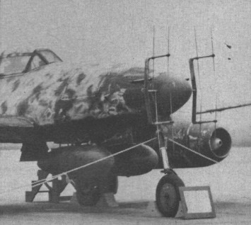
The Me 262A-2 night fighter is a radar-equipped two-seater, and has external tanks for additional range, a lengthened cockpit, and radar antenna.
In February 1945 the German 7th Fighter Wing under Col. Steinhoff, the only Luftwaffe wing armed with Me 262, reported that it was ready for deployment. Squadrons of the 3rd Fighter Wing assumed the task of protecting the jet fighters during take-off and landing. There was one other umit of Me 262 fighters, the 44h Fighter Group, whose commanders included General Galland – the fighter general removed from office by Goring – and several other fighter officers who had fallen into disfavour.
In March 1945 three Me 262A airframes were taken from the assembly line and converted as two seaters by substituting an 88-gallon fuel tank for the aft 198-gallon tank and using the created space for the observer’s seat. To compensate for the reduction of fuel, two 66-gallon drop tanks were attached under the fuselage and an FuGe 218 radar array was fitted in the nose. The standard four 30 mm MK108 armament was retained and it was proposed to tow a 198-gallon auxiliary tank to increase patrol endurance. This aircraft was designated Me 262B-2a; the first prototype crashed during flight trials, killing the observer.
Me.262B-1A
Me 262B-1a/U1
The Me 262B-1a/U1 was used for trials of the Lichtenstein SN-2 (FuG 220) interception radar and Hirschgeweih antennae, equipped with twin under fuselage auxiliary fuel tanks.
Me 262B-1a/U1
Tactics against the Me 262 developed quickly to find ways of defeating it despite its insurmountable speed. Allied bomber escort fighters (specifically P-51s) would fly high above the bombers to gain extra speed in a dive down to protect the bombers, thus reduce the speed advantage of the Me262. The Me262 was less manoeuvrable than the P-51 and trained allied pilots could catch up to a turning Me262; but the only reliable way of dealing with the jets was to attack them in the take-off and landing phase of their flight, and on the ground. Accordingly, Luftwaffe air fields that were recognized as jet bases were frequently bombed by medium bombers, and Allied fighters patrolled over the fields to attack jets that were trying to land on their bases. The Luftwaffe countered these moves by installing Flak alleys along the approach lines in order to protect the Me 262s from the ground, and providing top cover with conventional fighters during the take-off and landing phase.
A Hawker Tempest Mk.V was the first Allied plane to shoot down a Me262, and won number of victories over these jet fighters, while the Lavochkin was the only Soviet fighter to encounter a German jet, with La-7 ace Ivan Nikitovich Kozhedub fighting and downing one Me262 jet on February 15, 1945 over eastern Germany. Kozhedub apparently later said that his success was mainly due to the Me262 pilot attempting to out-turn his more manoeuvrable plane.
In the end, the overwhelming numbers of allied planes meant that the jets had no overall effect on the war. On March 18, 1945, 37 Me 262s intercepted a force of 1,221 bombers and 632 escorting fighters. They managed to shoot down 12 bombers and one fighter for the loss of three Me 262s. Although a four to one ratio was exactly what the Luftwaffe was dreaming about, it represented only one per cent of the attacking force — more were lost to mechanical problems.
Although the Me 262 had a negligible impact on the course of the war—shooting down an estimated 150 Allied aircraft for the loss of 100 Me 262s, the majority of aircraft grounded for lack of fuel.
Only 1,433 Me 262s were built, 500 of those destroyed during Allied bombings, leaving less than 300 jets to enter into the final days of combat.
Willy Messerschmitt regarded the Me 262 as it went into production only as an interim type. His interest in high-speed flight that had led him to initiate work on swept wings starting in 1940 is evident from the advanced developments he had on his drawing board in 1944. While the Me 262 HG I (Hochgeschwindigkeit – high speed) that was actually flight-tested in 1944 had only small changes compared to combat aircraft, most notably a low-profiled canopy to reduce drag, the HG II and HG III designs were far more radical. The projected HG II variant combined the low-drag canopy with a 35 degrees wing sweep and a butterfly tail. The HG III aircraft had a conventional tail, but a 45° wing sweep and the jet turbines embedded in the wing root.
Messerschmitt also conducted a series of carefully controlled flight tests with the series production Me 262. In these dive tests, it was established that the Me 262 was out of control in a dive at Mach 0.86, and that higher Mach numbers would lead to a nose-down trim that could not be countered by the pilot. The resulting steepening of the dive would lead to even higher speeds and disintegration of the airframe due to excessive negative g loads.
The HG series of Me 262 derivatives was estimated to be capable of reaching trans-sonic Mach numbers in level flight, with the top speed of the HG III being projected as Mach 0.96 at 6 km altitude. Despite the necessity to gain experience in high-speed flight for the HG II and III designs, Messerschmitt undertook no attempts to exceed the Mach 0.86 limit for the Me 262.
After the war, the Royal Aircraft Establishment — at that time one of the leading institutions in high-speed research — re-tested the Me 262 to help with the British attempts at breaking the sound barrier. The RAE achieved speeds of up to Mach 0.84 and confirmed the results from the Messerschmitt dive tests as accurate. No attempts were made to exceed the Mach limit established by Messerschmitt.
After Willy Messerschmitt’s death, the former Me 262 pilot Hans Guido Mutke claimed to be the first person to break the sound barrier on April 9, 1945 in a Me 262. This claim is only based on Mutke’s memory of the airspeed indicator reading and is disputed.
During the war the Germans set up a number of assembly plants in Czechoslovakia for the production of the Messerschmitt Me 262. After the war the manufacturing infrastructure remained intact, so production could start up again for the new owners.
All jigs, tools and components for the Messerschmitt Me 262 jet fighter in Czechoslovakia at the time of the German surrender were seized by the Soviet forces and then handed over to the newly restored Czechoslovak government by Marshal Ivan Konev. Forward fuselages and other components of the Me 262 had been manufactured at Letnany, some components had been produced in converted railway tunnels, and the CKD and Walter works had built the Junkers Jumo 004 turbojet, assembly of the fighters having been undertaken at Cheb, near the German border. Sufficient components were recovered for Avia to build 17 single- and two-seat Me 262s, the first single-seater flying as the S 92.1 on 27 August 1946.
The first Avia S 92.1 was assembled at Letnany Research Institute in 1945 (PL-01), with the airframe coming from Avia and the engines from the repair works in Malesice (the Junkers Jumo 004 now called the M-04). The S 92’s first flight was with Avia’s chief pilot Antonin Kraus in control. Tested pilots included RAF veteran Major Jiri Manak.
On 5 September, this aircraft was lost in an accident, a second, S 92.2, flying on 24 October, and what was referred to as the first series aircraft, a two seater (CS 92.3), following on 10 December. Dubbed the Turbina (Turbine), the S 92 was demonstrated to a Yugoslav delegation which placed an order with Avia for two examples, although, in the event, these were not delivered. The seventh aircraft, CS 92.7, was experimentally fitted with BMW 003 turbojets, the thrust of which had been boosted to 950kg, but flight testing was not entirely successful and the aircraft was re-engined to take the standard Jumo 004 turbojets. The eleventh and twelfth aircraft, S 92.11 and S 92.12 were completed during 1949.
Czech production included Avia S-92 code V-34(cn 51104), the fourth Czech-built. The fourth aircraft was first example armed with a pair of 30mm Rheimettal MK 108 cannon.
Avia S 92 Turbina
Delivery of the first S 92 to the Czech air force was in June 1948. In October 1950, with twelve being made in all (nine S 92 and three CS 92) equipping the 5th Fighter Flight at Mlada-Milovice airport, until they were grounded for use as instructional airframes in 1951. One of them is on display at the Prague Aero museum.
By the time Yugoslavia showed interest in buying the S 92, Avia was looking at closing down the production line to make way for new up to date aircraft and when Avia were given a licensed to make the Mig 15 (they were all ready making the Yak 23 as the S 101) the S 92 facilities were broken up.
Me 262 A1 Schwal Engines: 2 x Jumo 004 B-1, 8829 N Length: 34.777 ft / 10.6 m Height: 12.598 ft / 3.84 m Wingspan: 40.945 ft / 12.48 m Wing area: 233.579 sq.ft / 21.7 sq.m Max take off weight: 14103.2 lb / 6396.0 kg Weight empty: 8379.0 lb / 3800.0 kg Max. speed: 469 kt / 869 km/h Service ceiling: 37566 ft / 11450 m Wing loading: 60.48 lb/sq.ft / 295.0 kg/sq.m Range: 567 nm / 1050 km Crew: 1 Armament: 4x MK108 30mm
Me 262A-1a Type: single-seat fighter Engines: 2 x Junkers Jumo 004B-1/-2/-3 turbojets , 1,980lb (900kg) Span: 12.5m / 40 ft 11.5 in Length: 10.6m / 34 ft 9.5 in Height: 3.83m / 12 ft 6.75 in Wing area: 21.7 sq.m / 233.58 sq ft Ceiling: 11450 m / 37550 ft Empty weight: 4000kg Loaded weight: 7045kg Maximum speed: 540mph (870km/h) Climb rate: 1200m/min Ceiling: 11,500m Range on internal fuel: 1050km (650 Miles) Armament: 4 x 30mm MK 108 cannon / Two with 100 rounds each, two with 80
Me 262A-1a/U1 Engines: 2 x Junkers Jumo 004B turbojets , 1,980lb (900kg) Span: 12.5m Length: 10.6m Height: 3.8m Wing area: 21.7 sq.m / 233.58 sq ft Ceiling: 11450 m / 37550 ft Empty weight: 4000kg Loaded weight: 7045kg Climb rate: 1200m/min Ceiling: 11,500m Range on internal fuel: 1050km (650 Miles) Armament: 2 x 30mm MK 103, 2 x 30mm MK 108 cannon, 2 x 20mm MG 151/20
Me 262A-1b Engines: 2 x Junkers Jumo 004B turbojets ,1,980lb (900kg) Span: 12.5m Length: 10.6m Height: 3.8m Wing area: 21.7 sq.m / 233.58 sq ft Ceiling: 11450 m / 37550 ft Empty weight: 4000kg Loaded weight: 7045kg Climb rate: 1200m/min Ceiling: 11,500m Range on internal fuel: 1050km (650 Miles) Armament: 4 x 30mm MK 108 cannon / Two with 100 rounds each, two with 80, 24 spin-stabilised R4/M 55mm rockets
Me 262A-2a Type: single-seat bomber Engines: 2 x Junkers Jumo 004B turbojets ,1,980lb (900kg) Span: 12.5m Length: 10.6m Height: 3.8m Wing area: 21.7 sq.m / 233.58 sq ft Ceiling: 11450 m / 37550 ft Empty weight: 4000kg Loaded weight: 7045kg Maximum speed: 470 mph (755km/h) Climb rate: 1200m/min Ceiling: 11,500m Range on internal fuel: 1050km (650 Miles) Armament: 4 x 30mm MK 108 cannon / Two with 100 rounds each, two with 80 Bomb load: 2 x 500kg
Me 262B-1a Type: two-seat night fighter Engines: 2 x Junkers Jumo 004B turbojets ,1,980lb (900kg) Span: 12.5m Length excluding radar aerials: 11.8m Height: 3.8m Wing area: 21.7 sq.m / 233.58 sq ft Ceiling: 11450 m / 37550 ft Empty weight: 4000kg (B-1a 4400kg) Loaded weight: 7045kg (B-1a 6400kg) Maximum speed: 497 mph (800km/h) Climb rate: 1200m/min Ceiling: 11,500m Range on internal fuel: 1050km (650 Miles) Armament: 4 x 30mm MK 108 cannon / Two with 100 rounds each, two with 80
Me 262B-2a Engines: 2 x Junkers Jumo 004B turbojets ,1,980lb (900kg) Span: 12.5m Length: 10.6m Height: 3.8m Wing area: 21.7 sq.m / 233.58 sq ft Ceiling: 11450 m / 37550 ft Empty weight: 4000kg Loaded weight: 7045kg Climb rate: 1200m/min Ceiling: 11,500m Range on internal fuel: 1050km (650 Miles) Armament: 4 x 30mm MK 108 cannon / Two with 100 rounds each, two with 80, 2 x inclined MK 108 behind the cockpit in Schrage Musik installation (D) SG 500 Jagdfaust with 12 rifled mortar barrels inclined in nose (E) 50mm MK 114 gun or 48 R4/M rockets
Avia S.92 Turbina Engine: 2x Malesice M-04B (Jumo 004) turbojets Wing Span: 12.5 m / 41 ft 0 in Length: 10.58 m / 35 ft 9 in Height: 3.83 m / 13 ft 7 in Wing area: 21.80 sq.m / 234.65 sq ft Weight: Empty 4,000 kg / 8819 lb MTOW: 7,045 kg / 15532 lb Maximum Speed: 870 km/h / 541 mph Rate of climb: 1220 m/min / 4000 ft/min Ceiling: 11,450 m / 37550 ft Range: 1,050 km / 652 miles Crew: 1 Armament: 4x 30 mm cannon
Avia CS.92 Engine: 2 x Malesice M-04B (Jumo 004) turbojets Wing Span: 12.5 m Length: 10.58 m Height: 3.83 m Weight: Empty 4,000 kg / Loaded 7,045 kg Maximum Speed: 870 km/h Ceiling: 11,450 m Range: 1,050 km Crew: 1 Armament: 4x 30 mm cannon
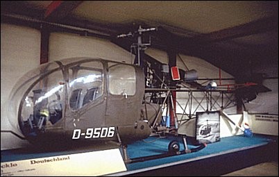
First turbine-powered helicopter built and flown in Germany, the five-seat Merckle SM 67 development began as a private venture in 1956, but the third prototype, which flew for the first time on April 12,1961, was bought by the Federal Government and spent much of last year undergoing an official flight test and evaluation programme.
More refined than its predecessors, it has a fully enclosed cabin and is powered by a 406shp Turbomeca Artouste IIC shaft turbine, driving a three-blade main rotor and two-blade tail rotor.
SM-67 Engine: 406shp Turbomeca Artouste IIC Rotor diameter: 10.49m Overall length: 12.75m Height: 2.8m Gross weight: 1700kg Empty weight: 1037kg Max speed: 220km/h Cruising speed: 190km/h Hovering ceiling OGE: 3500m Range with full payload: 360km Payload: 300kg
M&D Flugzeugbau are a German company based in Friedeburg, Lower Saxony in north-western Germany. M&D Flugzeugbau manufacture the Samburo motorglider and also provide maintenance services for other light aircraft.
In 2007 M&D identified the potential benefits of installing a small jet turbine sustainer in gliders but considered the range of jet turbines available for model aircraft had limitations. Such engines had not been designed from the outset to consider certification or in-flight starting. M&D decided that rather than convert a model aircraft jet turbine into a glider sustainer, it would be better to develop and certificate a new engine.
The key features of the TJ42 engine are: Single spool jet turbine Two stage axial-centrifugal stator-less compressor with a compression ratio of 1:3.8 Cannular combustor with multiple fuel injectors and combustion zones contained within a single annulus casing Glow-plug ignition system (used in start-up sequence only, ignites top combustion zone only) Single stage axial turbine with stators Convergent nozzle Front-mounted, direct drive electric starter motor for initial spool up
The maximum thrust is nominally 42 kgf at 100,000 rpm with an estimated fuel consumption of 66.4kg/hr at full thrust. At the idle speed of 30,000 rpm the thrust is less than 2 kgf. The weight is 3.3kg and overall dimensions 400 mm long and 150 mm diameter.
The TJ42 has a kerosene start-up (as opposed to gas start engines) which eliminates the need for separate gas canisters and long complex start-up procedures.
The start-up sequence is: Glow-plug heats up for 10 seconds Electric starter motor spools up engine to 8,000 rpm Starter fuel solenoid pulses with fuel being injected into the top combustion zone only Fuel ignited in top combustion zone by glow-plug Engine spools up to 15,000 rpm Normal fuel solenoid pulses with fuel being injected into all combustion zones (starter fuel solenoid closes) Engine spools up to idle speed of 30,000 rpm Fuel rate controlled by throttle, and matched to density altitude and rpm by ECU
The shut-down sequence is: Fuel cut off and combustion ceases With no fuel, the engine speed decreases and EGT decreases
The ECU senses EGT and rpm, and if the engine speed is too low to promote rapid cooling, the electric starter motor runs an automatic cooling cycle (spooling the engine up to 3,000 rpm, then switching off)
Once the EGT has dropped below 50°C the ECU signals that the engine can be retracted
The engine and pylon are enclosed by cowlings manufactured from fiberglass and aluminum (or possibly stainless steel subject to clarification of certification requirements).
The MD-TJ42 is certified for installation on self-sustaining sailplanes only, i.e. it is not intended for take-off operation, EASA Type Certificate EASA.E.099. The first type certificated application was on the Jonker Sailplanes JS-1 Series.
Because of the use of these engines in sailplanes, there are several assumptions to simplify the requirements for certification. These assumptions are:
the engines will be used for self-sustaining sailplanes only, not intended for take off;
no bleed air, no reverse functions;
no flight in icing or hail conditions;
no aerobatic operation;
the turbine engine is not used to drive accessories that are essential for any other means than the turbine itself;
the strike and ingestion of foreign matter can be treated as extremely remote, because the engine is started and shutdown in f1ight. Ground operation will only take place for maintenance purposes.
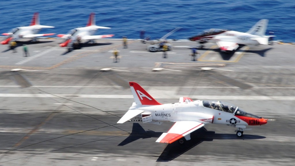
Derived from the British Aerospace Hawk advanced trainer, the US Navy’s carrier-capable T-45A Goshawk prototype was scheduled to fly before the end of 1987, with service entry due in 1990. The Hawk was selected in 1981 as the aircraft element of the new VTX-TS training system, and a fixed-price contract covering the first three production lots and 15 simulators was signed in May 1986. Total cost of the T-45TS package, including 300 production aircraft, two prototypes, simulators, computerised instruction and integration system, and logistics support is estimated at $4,500 million. British Aerospace is the principal airframe subcontractor, building the wings, rear fuselage, canopy, and flight controls, although final assembly and some component manufacture will be undertaken by McDonnell Douglas in the USA.
Changes from the basic Hawk design include a twin-wheel nose gear for catapult launching, a strengthened maingear to allow high-sink-rate landings, an arrester hook, rear side-fuselage airbrakes, and a cockpit modified to USN requirements. The empty weight of the T-45A will be 4,261kg, and maximum take-off weight 5,787kg, with an internal fuel load of 1,363kg. Approach speed will be 222km/hr (121 kt), maximum level speed Mach 0.85, and average fuel consumption 620kg/hr on a typical training sortie. Weapons delivery capability for armament training were be incorporated.
The T-45 Goshawk, of which the Navy owns 193 aircraft, is a jet trainer fleet used by the Navy and Marine Corps to qualify new pilots. Originally produced by what is now Boeing and derived from an earlier British aircraft made by BAE Systems, its first iterations joined the US Navy’s fleet in the 1990s.
BAe / Boeing T 45 C Goshawk Engine: Rolls Royce/Turboméca F 405-RR401 (Adour Mk. 871), 25977 N / 2648 kp Length: 39.272 ft / 11.97 m Height: 13.419 ft / 4.09 m Wingspan: 30.807 ft / 9.39 m Wing area: 179.651 sq.ft / 16.69 sq.m Max take off weight: 14083.3 lb / 6387.0 kg Weight empty: 9399.9 lb / 4263.0 kg Max. speed: 543 kts / 1006 km/h Initial climb rate: 6982.28 ft/min / 35.47 m/s Service ceiling: 42503 ft / 12955 m Wing load: 78.52 lb/sq.ft / 383.0 kg/sq.m Range: 999 nm / 1850 km Crew: 2 Hardpoints: 3
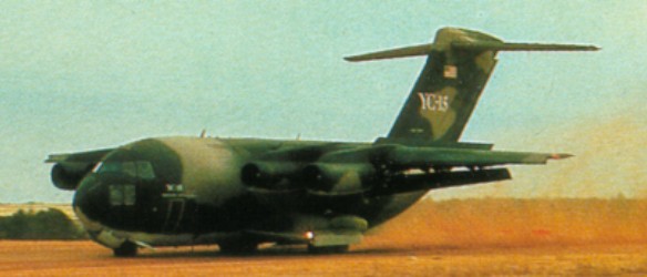
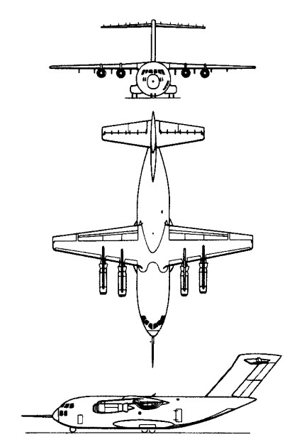
The McDonnell Douglas YC 15 first prototype (72 1875), an advanced military STOL transport, made the type’s maiden flight on 26 August 1975. Designed to contend against Boeing YC 14 pro¬totypes for the USAF’s advanced medium short take off and landing transport (AMST) requirement, it had an externally blown flap system that depended on the slipstream from four turbofan engines. The first flight was made three months ahead of schedule and the two YC-15 prototypes flew for three years before the test program ended.
YC-15 Engines: 4 x Pratt & Whitney JT-8D-17, 71.1kN Max take-off weight: 68000 kg / 149915 lb Wingspan: 33.6 m / 110 ft 3 in Length: 37.9 m / 124 ft 4 in Height: 13.2 m / 43 ft 4 in Wing area: 161.7 sq.m / 1740.52 sq ft Max. speed: 805 km/h / 500 mph Range w/max.fuel: 4800 km / 2983 miles Crew: 2-3
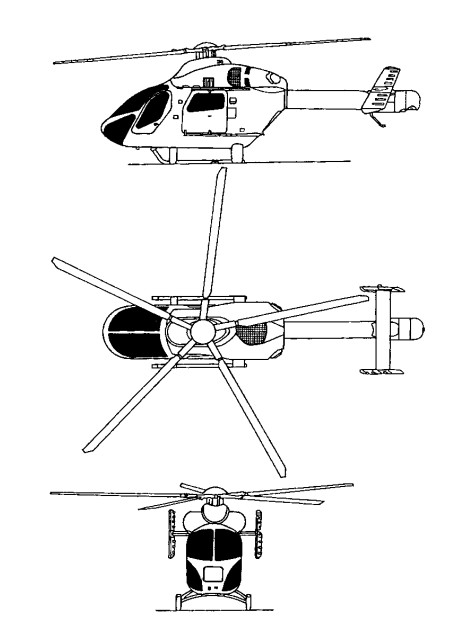
The genesis of the Explorer dates to 1986, when company engineers hit upon the idea of using the latest technology, such as an all-composite main rotor and MDHS’ own no-tail-rotor (NOTAR) anti-torque system, as a basis for a new eight-seater design which would give excellent performance at affordable cost. The MD Explorer is the first commercial helicopter totally designed using computer-aided design techniques and only after a detailed market survey of over 177 operators asking them what they wanted from a new utility helicopter in terms of flight performance and general layout in a 1800 to 3600kg helicopter.
MDHS decided to go ahead with design work in January 1989 with a senior advisory council formed from risk-sharing partners in the $200 million programme. The Explorer is created using computer-aided design (CAD) techniques. The Explorer is the first helicopter to have a major portion of its primary structure constructed from composites. This is most evident in the fuselage, which is manufactured by Hawker de Havilland in Australia. Skins, floors, mb/keel beam and aft-fuselage assemblies are made from a pre-impregnated carbon-fibre composite with a toughened epoxy resin system produced by Hexel. Hawker de Havilland refined manufacturing techniques after the first three fuselage units and standardised on a final design which is around 10% lighter than the development fuselages, weighing in at just 260kg. Metallic parts consist of the titanium roof which provides protection from fire in the engine area, the main frames, fittings and forward-cockpit structure. Two aluminium plough beams form the primary structural support for the nose and provide enhanced crash-protection. In the event of a forward impact with the ground, the beams are designed to keep the nose of the helicopter from tipping down. In the passenger configuration, the Explorer’s 1.44m-wide cabin provides enough space for two rows of three 480mm seats , with a seventh passenger seated in the co-pilots position. Without seats, the helicopter has a completely flat floor which is accessible via a rear-access door and large sliding doors on either side of the cabin. The tailboom and empennage are all-composite primary structures made by MDHS using the same carbon composite and toughened resin as the fuselage. Like the fuselage, the early tailboom design was altered slightly for the final-production configuration to give a 25% weight saving. As the tailboom is hollow to accommodate the NOTAR system, it has aerodynamic surfaces on the inside, as well as the outside. Slots run the length of the right-hand side of the boom to allow air to escape and create the Coanda effect at the heart of the NOTAR principle.
Initially known as MDX, then MD 900 (proposed MD 901 with Turbomeca engines was not pursued. Hawker de Havilland of Australia designed and manufactures airframe; Canadian Marconi tested initial version of integrated instrumentation display system (IIDS) early 1992; Kawasaki completed 50 hour test of transmission early 1992. Other partners include Aim Aviation (interior), IAI (cowling and seats) and Lucas Aerospace (actuators).
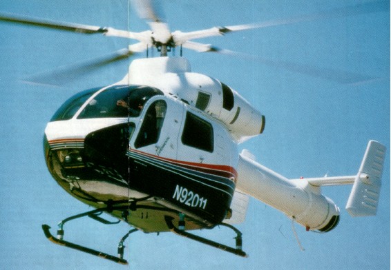
Ten prototypes and trials aircraft, of which seven (Nos. 1, 3-7 and 9) for static tests, were built. The first flight (No.2/N900MD) was on 18 December 1992 at Mesa, Arizona, followed by No.8/N900MH 17 September 1993 and No.10/N9208V 16 December 1993; first production/demonstrator Explorer (No.11/N92011) flown 3 August 1994.
FAA certification 2 December 1994; first delivery 16 December 1994; JAA certification July 1996; FAA certification for single-pilot IFR operation achieved January 1997. Type certificate transferred to MDHI on 18 February 1999.
This new technology helicopter received type certification on 21 December 1994 from the FAA which was only 23 months after first flight. This was one of the shortest certification periods ever recorded for a new helicopter and was also the first new design passenger and utility rotorcraft certified by the FAA in more than ten years.
FAA certification of uprated PW207E engine achieved in July 2000, providing 11% more power for take-off and 610m increase in hovering capability OEI in hot-and-high conditions; first delivery of PW207E-engined Explorer to Police Aviation Services, UK, 27 September 2000. “100th production” Explorer (actually 89th overall, including prototypes) delivered 1 March 2002 to Tomen Aerospace Corporation of Japan for ENG operations by Aero Asahi of Hiroshima. Total fleet time stood at more than 120,000 hours by December 2002.
MDHS begun delivery of the Explorer with a target direct-operating cost of $389/h and a base price of $3.16 million at 1995 exchange rates.
The Explorer has been built largely from composite materials and is powered by twin Pratt & Whitney Canada PW 206A turboshafts and has a maximum gross weight of 2950kg. It can lift 1150kg internally, or 1350kg externally and weighs only 1350kg empty. The helicopter incorporates a range of new technologies to improve safety and performance and reduce operating costs. These include the NOTAR yaw control system, composite, bearingless main rotor with five blades. Digital avionics including FADEC, diagnostics and an Integrated Instrument Display System. The liquid crystal Integrated Instrument Display System (IIDS) replaces traditional cockpit instruments by presenting aircraft operating information in a digital format and icon symbology on two six-inch screens. The system also records operating data for on-board health and usage monitoring, providing technicians with accurate information for performing maintenance functions.
The NOTAR anti-torque system features all-composites five-blade rotor of tapered thickness with parabolic swept outer tip with bearingless flexbeam retention and pitch case; tuned fixed rotor mast and mounting truss for vibration reduction; replaceable rotor tips; maximum rotor speed 392 rpm; modified A-frame construction from rotor mounting to landing skids protects passenger cabin; energy-absorbing seats absorb 20 g vertically and 16 g fore and aft; onboard health monitoring, exceedance recording and blade track/balance.
Mechanical engine control from collective pitch lever is back-up for electronic FADEC. Automatic stabilisation and autopilot available for IFR operation. The transmission overhaul life 5,000 hours; glass fibre blades have titanium leading-edge abrasion strip and are attached to bearingless hub by carbon fibre encased glass fibre flexbeams; rotor blades and hub on condition.
The baseline MD 900 is powered by two Pratt & Whitney Canada PW206E turboshafts with FADEC, each rated at 463kW for 5 minutes for T-O, 489kW for 2.5 minutes OEI and 410kW maximum continuous. Transmission rating 820kW for T-O, 746kW maximum continuous, 507kW for 2.5 minutes OEI and 462kW maximum continuous OEI.
Fuel contained in single tank under passenger cabin, capacity 564 litres, of which 553 litres are usable. Single-point refuelling; self-sealing fuel lines.
Accomodation is for two pilots or pilot/passenger in front on energy-absorbing adjustable crew seats with five-point shoulder harnesses/seat belts; six passengers in club-type energy-absorbing seating with three-point restraints; rear baggage compartment accessible through rear door; cabin can accept long loads reaching from flight deck to rear door; hinged, jettisonable door to cockpit on each side; sliding door to cabin on each side.
Hydraulic system, operating pressure 34.475 bar.
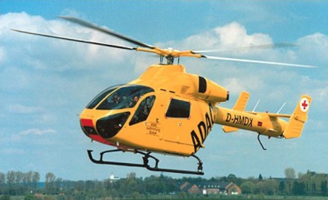
With 14 feet of flat floor space in the rear cabin, the Explorer is expected to undertake a multitude of civil missions from general utility to offshore transportation, corporate flight, tourist flights and air medical services. In the EMS configuration the Explorer can accommodate two patients, two attendants and life support equipment in addition to the flight crew.
The 100th Explorer registered in 2002 (to become seventh for Netherlands police); total of 108 manufactured by December 2002; first delivery 16 December 1994 to Petroleum Helicopters Inc (PHI) which ordered five; second delivery (N901CF) December 1994 to Rocky Mountain Helicopters for EMS duties with affiliate Care Flight unit of Regional Emergency Medical Services Authority (REMSA) in Reno, Nevada. Total of two delivered in 1994, 12 in 1995, 15 in 1996, one in 1997, four in 1998, 11 in 1999, 16 in 2000, 20 in 2001 and four in 2002; initial (MD 900) series comprised 40 aircraft including three flying prototypes; FW207E engine from 64th production (67th overall) aircraft.
MD Enhanced Explorer: Improved version, announced September 1996; originally MD 902, but now known as “902 Configuration”. Main features include Pratt & Whitney Canada PW206E engines with increased OEI ratings; transmission approved for dry running for 30 minutes at 50% power; improved engine air inlets, NOTAR inlet design and engine fire suppression system, and more powerful stabiliser control system, resulting in 7% increase in range. 4% increase in endurance and 113kg increase in payload over Explorer. First flight (N9224U; c/n 900-0051, 41st Explorer) 5 September 1997, FAA certification to Category A performance standards (including continued take-off with one failed engine) and single-pilot IFR operation achieved 11 February 1998; JAA certification for Category A performance achieved July 1998. Retrofit kits to convert Explorers to Category A standard. First Enhanced Explorer delivery in May 1998 to Tomen Aerospace of Japan. PW206E replaced by PW207E from late 2000, beginning at c/n 900-0077, allowing further MTOW increase to 2,948kg.
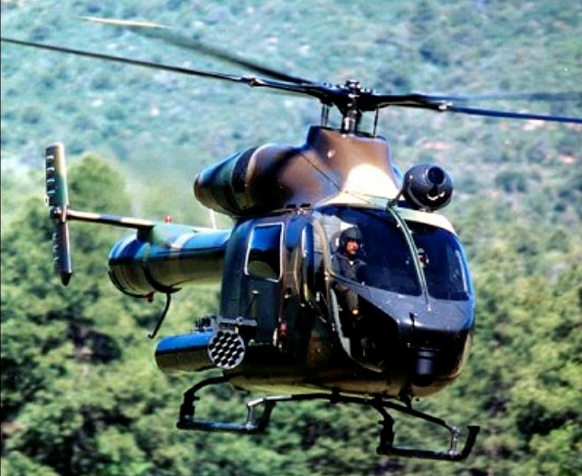
MH-90 Enforcer: Beginning March 1999, under a programme code-named Operation New Frontier, the US Coast Guard used two leased MD 900 Explorers for shipboard anti-drug smuggling operations. Armed with a pintle-mounted M240 7.62mm minigun at the door station. In September 1999 the MD900s were exchanged for two leased MD 902 Enhanced Explorers. These subsequently replaced by Agusta A 109s. Six delivered to Mexican Navy at Acapulco (two each respectively in May and December 1999 and April 2000) for anti-drug operations, equipped with 12.7mm General Dynamics GAU-19/A Gatling guns, and 70mm rocket pods; further four in process of delivery. Weapons qualification trials were completed at Fort Bliss, Texas in November 2000.
Combat Explorer: Displayed at Paris Air Show, June 1995; demonstrator N9015P (No.15), an MD 900 variant. Can be configured for utility, medevac or combat missions; armament and mission equipment may include seven- or 19-tube 70mm rocket pods, 12.7mm machine gun pods, chin-mounted FLIR night pilotage system and roof-mounted NightHawk surveillance and targeting systems. Combat weight 3,130kg; two P&WC PW206A engines. No customers announced by January 2000, but N9015P became one of initial two MH-90s (with third prototype, N9208V).
February 19, 1999: Boeing sold MD commercial line to RDM The dutch company bought the ex Mc Donnell Douglas models MD 500E and MD 530F single-engine helicopters with conventional tail rotors, the MD 520N and MD 600N single-engine NOTAR helicopters and the MD Explorer series of twin-engine, eight-place helicopters.
Costs: US$2.285 million (2002); direct operating cost US$408.11 (2002) per hour.
McDonnell Douglas MD 902 Explorer Engine: 2 x Pratt & Whitney Canada PW206E, 630 shp Length: 32.316 ft / 9.85 m Height: 12.008 ft / 3.66 m Rotor diameter: 33.825 ft / 10.31 m Wing area: 3939.624 sqft / 366.0 sq.m Max take off weight: 6504.8 lb / 2950.0 kg Weight empty: 3214.9 lb / 1458.0 kg Max. speed: 160 kts / 296 km/h Cruising speed: 140 kts / 259 km/h Initial climb rate: 2795.28 ft/min / 14.2 m/s Service ceiling: 18497 ft / / 5638 m Wing load: 1.64 lb/sq.ft / 8.0 kg/sq.m Range: 313 nm / 580 km Crew: 2 Payload: 8pax
MD Explorer Engine: 2 x Turbomeca Arrius 2C Instant pwr (Turbomeca engine): 480 kW. Rotor dia: 10.3 m MTOW: 2700 kg Useful load: 1165 kg Max cruise: 150 kts Max range: 600 km Seats: 8
MD Explorer Engine: 2 x P&WC PW206A Gross wt: 2,722kg Empty operating wt: 1,481kg Useful load: 1,163kg Fuel capacity wt (600litres): 438/472kg Main rotor dia: 10.34m Length: 9.86m Height: 3.66m Skid width: 2.23m Passengers: 7. Crew: 1 Max cruise speed @ ISA 38oC: 135kt (@sea level ISA: 139kt) Max range: 530km Max endurance: 3.5hr Hover Out of ground effect @ ISA: 3,353m (@lSA+20o: 2,073m) Hover in ground effect @ ISA 3901m (@lSA+20o: 2,621m) Climb rate: 14.2m/s Ceiling: 20,000ft
MD 900 Explorer Engines: 2 x Pratt & Whitney PW 206B turboshaft, 469kW Rotor diameter: 10.31m Length with rotors turning: 11.83m Fuselage length: 9.85m Height: 3.66m Fuselage width: 1.63m Max take-off weight: 3057kg Empty weight: 1481kg Max speed: 278km/h Cruising speed: 250km/h Rate of climb: 14.2m/s Hovering ceiling: 3840m Service ceiling: 6100m Range: 530-600km Payload: 1360kg Crew: 1-2 Passengers: 6
On 8 November 1994, McDonnell Douglas announced their plans to develop an eight-place version of their popular MD520N helicopter. They surprised the world’s press in January 1995 when they flew their new helicopter to Heli-Expo 95 in Las Vegas, Nevada. The prototype, then known as MD 630N (N630N, converted from MD 530F demonstrator), first flew 22 November 1994, 138 days after project approval. After their public debut at Heli-Expo the first year’s production was sold out on the first day.
Production go-head was given on 28 March 1995, at which time designation changed to MD 600N; and a prototype was first flown with production standard engine and rotor system on 6 November 1995.
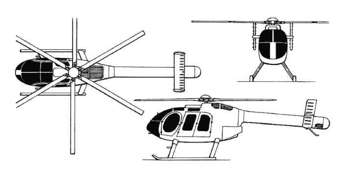
The 600N has a 33in lengthened fuselage centre section with double, centre opening doors, which gives access to a six-foot long flat floor with seating for five passengers in this rear cabin and three across the front seats. The complete fuselage of these helicopters are built under contract by helicopter manufacturer Kaman Aerospace. The six bladed fully articulated main rotor system shares many components with the MD500 series machines, and power comes from an 800-shp Rolls-Royce Allison 250-C47M turboshaft engine, which is derated to 600 shp for take-off and 530 shp for maximum continuous. The engine is equipped with FADEC as well as a manual backup hydro-pneumatic fuel system.
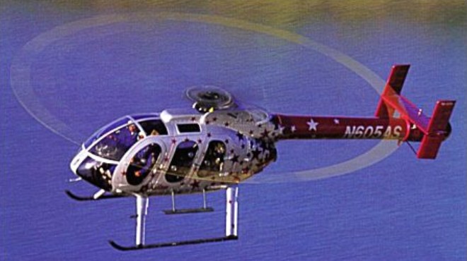
Production prototype (N600RN) first flown 15 December 1995, and became certification test vehicle leading to FAR Pt 27 certification, but was destroyed in ground fire 28 May 1996, following emergency landing after rotor/tailboom strike during abrupt control reversal tests. This resulted in changes to tailboom/rotor clearance; third prototype (N605AS) flown 9 August 1996; further accidents to N630N on 4 and 21 November 1996 and on 18 January 1997, all during autorotational descents, culminated in total loss and delayed certification and first delivery, originally scheduled for 18 December 1996, to 15 May and 6 June 1997, respectively. MD 600N certified on MD500 certificate. The FAA Certification was received on 15 May 1997. The first delivery was on 6 June 1997, N605AS, to AirStar Helicopters.
The 630N features a stretched MD 520N airframe (less than 1% new parts) by means of 0.76m plug aft of cockpit/cabin bulkhead and 0.71m plug in tailboom, combined with more powerful engine, uprated transmission and six-blade main rotor. Cabin has flat floor to assist cargo handling, and will feature quick-change interior configurations to suit multiple-use operators. Intended for civil, utility, offshore, executive transport, medevac, aerial news gathering, touring, law enforcement and other noise-sensitive operations; also adaptable for armed scout, utility and other military missions.
Powered by one 603kW Rolls-Royce 250-C47M turboshaft, derated to 447kW for T-O (5 minutes) and 395kW maximum continuous, with FADEC. Transmission manufactured from WE43A magnesium alloy for lower weight, greater strength and enhanced corrosion resistance, rating 447kW. Fuel contained in two crashworthy bladder tanks in lower fuselage, total capacity 440 litres, of which 434 litres are usable.
The electrical system comprises 28V 200Ah starter-generator and 28V 17Ah Ni/Cd battery. 24V auxiliary power receptacle inside starboard cockpit door standard.
In July 1998, Boeing completed a year-long envelope expansion programme for the MD 600N leading to FAA approval for operation at a density altitude of 2,135m at a T-O weight of 1,746kg and at a density altitude of 1,220m at a T-O weight of 1,860kg. Other performance enhancements approved by the FAA included provision for doors-off operation at speeds up to 213km/h, operation at temperatures -40°C/52°C, lifting up to 968kg on the external cargo hook, making slope landings up to 10° in any direction, operation with emergency floats and for installation of a movable landing light and additional wire strike protection on the fuselage. The MD 600N also completed HIRF trials at NAS Patuxent River, Maryland. Yaw-stability augmentation system (Y-SAS) was under development during 2000, aimed at reducing pilot workload during extended flights and in turbulent conditions.
Total of 68 registered by May 2003. Launch customer AirStar Helicopter of Arizona (two, of which first delivered 6 June 1997); Saab Helikopter AB of Sweden and Rotair Limited of Hong Kong ordered one each in June 1995; other customers include Guangdong General Aviation Company (GGAC) of the People’s Republic of China, which took delivery of one MD 600N in November 2000, during Airshow China 2000 in Zhuhai, Los Angeles County Sheriff’s Department Aero Bureau (three), Orange County, California, Sheriff’s Department, Indianapolis, Indiana. Police Department (one), Presta Services of France (one), Turkish National Police, which ordered 10 in December 2000 for delivery during 2002 (subsequently postponed to 2003), UND (University of North Dakota) Aerospace (one), West Virginia State Police (one) and the US Border Patrol (45, of which 11 delivered by end of 1998. when procurement halted pending evaluation of UAVs for border patrol role). Deliveries totalled 15 in 1997, 21 in 1998, six in 1999, seven in 2000, two in 2001 and two in 2002.
Costs: US$1.315 million (2002).
February 19, 1999 : Boeing sold MD commercial line to RDM The dutch company bought the ex Mc Donnell Douglas models MD 500E and MD 530F single-engine helicopters with conventional tail rotors, the MD 520N and MD 600N single-engine NOTAR helicopters and the MD Explorer series of twin-engine, eight-place helicopters.
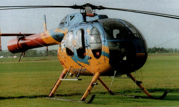
Military variants known as Defenders (AH-6E, MH-6F) carry TOW missiles, FLIR, mast-mounted sight, etc. The Model 530 Defender (has refined aerody¬namics and more power the OH-6), and AH-6 (Model 530 version for US Special Forces).
February 19, 1999: Boeing sold MD commercial line to RDM The dutch company bought the ex Mc Donnell Douglas models MD 500E and MD 530F single-engine helicopters with conventional tail rotors, the MD 520N and MD 600N single-engine NOTAR helicopters and the MD Explorer series of twin-engine, eight-place helicopters.
MD 530N
Commercial MD 520N and uprated (485 kW Rolls Royce 250-C30) MD 530N NOTAR helicopters announced February 1988 and officially launched January 1989. The first production prototype MD 530N (N530NT) flew on 29 December 1989, but this variant not pursued.
Flight testing of the MD 530N indicated capabilities greater than expected. With only 25.2 hours logged, a series of aerobatic manoeuvres were performed during June 1990, including loops, rolls, hammerheads and Split ‘S’ manoeuvres. In other tests the envelope was expanded to a maximum internal gross weight of 33500 lb / 1520 kg.
MD530F Engine: 1 x Allison 250-C30, 650 shp Instant pwr: 313 kW Rotor dia: 8.35 m MTOW: 1405 kg Useful load: 685 kg Max cruise: 135 kts Max range: 381 km HIGE: 14,300 ft HOGE: 12,000 ft Crew: 1 Pax: 3 Seats: 5
530MG Defender Engine: 1 x Allison 250-C30 Installed pwr: 317 kW Rotor dia: 8.4 m Fuselage length: 9.8 m No. Blades: 5 Empty wt: 664 kg MTOW: 1610 kg Payload: 901 kg Max speed: 240 kph ROC: 505 m/min Ceiling: 4200 m HIGE: 2315 m HOGE: 1770 m Fuel cap (+aux): 240 lt ( 80 lt ) Range: 443 km Crew: 1 Pax: 5