Failure to meet predicted performance and poor reliability under test had led to some disenchantment with the large Lyulka TR-3 turbojet specified for the 1950 supersonic fighter programme. In consequence, the MiG 0KB elected to initiate development of a derivative of its contending TR-3-powered I-¬350 as a back-up programme, this, the 1-360 (SM-2), having close-paired Mikulin AM-5 small-diameter turbojets but being otherwise similar.
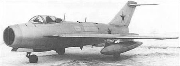
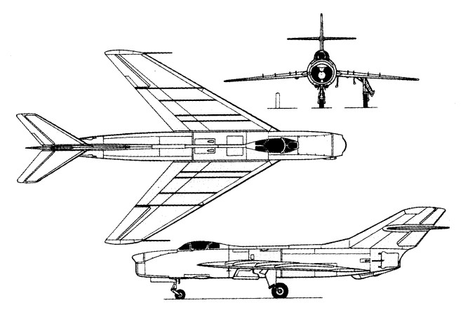
The SM-2 single-seat fighter proposal embodying an essentially similar wing to that of the I-350 with 55° sweepback at quarter chord (60° at leading edge). Powered by two AM-5F turbojets each with an afterburning rating of 2700kg and having an armament of two 37mm N-37D cannon in the wing roots, the first SM-2 – by now assigned the official designation of I-360 – was flown on 24 May 1952.
This was unique in having a T-type horizontal tail, and, on 25 June, it attained Mach=1.04 in level flight. Subsequent testing revealed that the wing tended to blanket the tailplane at high angles of attack, and, to rectify this deficiency, the tailplane was lowered to a mid point on the fin. Flight test (as the SM-2A) revealed little improvement and the surface was then further lowered to the base of the fin (as the SM-2B), this being accompanied by some increase in the vertical tail surface area, and satisfactory handling characteristics resulting.
The trials conducted (comprising 132 flights) ended in the loss of the aircraft in 1953 as a result of tail flutter at high speed, together with those of a further prototype, the SM-9 which had joined the test programme on 27 May 1952, were considered sufficiently successful to warrant immediate preparations for manufacture of a pre-series under the designation M1G-19.
Max take-off weight: 6820 kg / 15036 lb Wingspan: 9.04 m / 29 ft 8 in Length: 13.90 m / 45 ft 7 in Height: 3.95 m / 13 ft 0 in
As the MiG OKB’s Izdeliye M contribution to a 1950 programme to develop a single-seat fighter powered by a single Lyulka TR-3A single-shaft turbojet which was to be committed to production as the AL-5, and capable of attaining and maintaining a speed in excess of M = l.0 in level flight, the 1-350 was flown on 16 May 1951.
Characterised by 60° wing sweepback, T-tail, and assigned the official designation I-350, one prototype was built, the M-1 with RP-1 Izumrud AI radar, a second, the M-2 with Korshun AI radar, being abandoned before completion. Armament comprised one 37mm N-37 and two 23mm NR-23 cannon.
The M-1 was flown for the first time on 16 June 1951, but the TR-3A turbojet, which was rated at 4600kg, failed shortly after take-off. The hydraulic system also failed, but the pilot nonetheless effected a successful landing.
The Lyulka¬ engined prototype was, in consequence, rebuilt with a paired Mikulin AM-5 engine installation similar to the I-360 (SM-2). The destruction of the latter under test led to a delay in the resumption of flight testing of the I-350 pending redesign of the tail assembly transferring the horizontal surfaces to the fuselage. With this change and AM-5 engines, the prototype commenced test on 18 September 1953 as the 1-350(M), but lack of afterburning prevented M = 1.0 being exceeded in level flight.
Four further flight tests were performed, but engine difficulties persisted, and, as it was obvious that the Lyulka turbojet demanded considerable further development, the I-350 programme was terminated in August 1951.
I-350 (estimated) Max take-off weight: 8710 kg / 19202 lb Empty weight: 6125 kg / 13503 lb Wingspan: 9.73 m / 31 ft 11 in Length: 16.65 m / 54 ft 8 in Wing area: 36.00 sq.m / 387.50 sq ft Max. speed: 1266 km/h / 787 mph Range: 1120 km / 696 miles
In the early 1950s, the MiG OKB was engaged in the simultaneous development of MiG-17 de¬rivatives and potential successors to the M1G-17. A derivative was the SM-1, or 1-340, which mated the forward fuselage, wings and tail surfaces of the MiG-17 with a new centre and rear fuselage accommodating paired 4,850 lb st (2 200 kgp) Mikulin AM-S single-shaft turbojets. Trials with the SM-1, which apparently commenced at the beginning of 1952, were largely concerned with the engine installation as similarly paired AM-5s had meanwhile been selected to power a more advanced fighter, the 1-360. In consequence, the SM-1 did not progress beyond prototype status. Earlier, in 1951, another MiG-17 airframe had been fitted with a Lyulka TR-3 axial-flow turbojet of 10,140 lb st (4600 kgp) as the S1-16, this serving as a test-bed for the I-350, and in 1953, yet a further MiG-17 airframe, the SR-2, was to be fitted with a Kliinov VK-5F centrifugal-flow turbojet of 6,834 lb st (3100 kgp), this being the ultimate Soviet development of the Rolls-Royce Nene. No performance data or weights are available for the SM-1, and overall dimensions were similar to those of the MiG-17F apart from a length of 36 ft 11 in (11,25 m) and a height of 12 ft 7.9 in (3,86 m).
Max speed: 1193kph at 1000m / 1154kph at 5000m Time to 5000m: 0.94 min
Designed to meet the demands of a twin-engined all-weather fighter programme initiated in January 1948, the MiG OKB offered the Izdeliye R, a side-by-side two-seat swept-wing fighter with the engines in tandem. The nose intake fed a plenum chamber around the forward engine compressor, this engine exhausting below the fuselage and a duct leading back to the aft engine which exhausted via an orifice in the extreme tail. Armament comprised three 37mm N-37 cannon.
Competing with proposals from the Lavochkin and Yakovlev bureaux – all three contenders being awarded three-prototype contracts – the MiG fighter was assigned the official designation I-320.
The first prototype, the R-1 powered by two 5,005 lb st (2270 kgp) RD-45F engines, was flown on 16 April 1949.
The R-2 and R-3 were each powered by paired of 5,952 lb st / 2700kg VK-1 engines and embodied various modifications, the R-3 featuring a strength¬ened wing. The VK-1-powered prototypes could take-off and cruise on the power of either engine, and the I-320 was initially tested with Torii-A (Thorium-A) radar mounted in a cone above the air intake. This single-antenna radar which demanded manual tracking was succeeded by the basically similar but improved Korshun (Kite) radar with which the I-320 was tested during July-August 1951. Development of the I-320 was discontinued when the requirement to which it had been designed was overtaken by a more advanced one. Develop¬ment was discontinued in favour of the Yak-25 which was capable of accommodating a larger radar.
1-320 (R-1) Engines: 2 x RD-45F, 5,005 lb st (2 270 kgp) Max speed, 658 mph (1 060 km/h) at 14,765 ft (4 500 m) Ceiling, 49,540 ft (15 100 m) Endurance, 3.0 hrs Empty weight, 16,241 lb (7 367 kg) Loaded weight, 22,630 lb (10 265 kg) Span, 46 ft 7 in (14,20 m) Length, 51 ft 8 7/8 in (15,77 m) Wing area, 443.47 sq ft (41,20sq.m)
I-320 R-2 Max take-off weight: 12095 kg / 26665 lb Wingspan: 14.20 m / 46 ft 7 in Length: 15.77 m / 51 ft 9 in Wing area: 41.20 sq.m / 443.47 sq ft Max. speed: 1090 km/h / 677 mph Range: 1205 km / 749 miles
The initial Microturbo product offering was the “Noelle” starter turbine, which led to a number of starter / APUs such as the “Emeraude”, “Espandon”, and “Saphir”. The Emeraude led to the company’s first turbojet, the small and simple Eclair, intended for self-launching sailplanes.
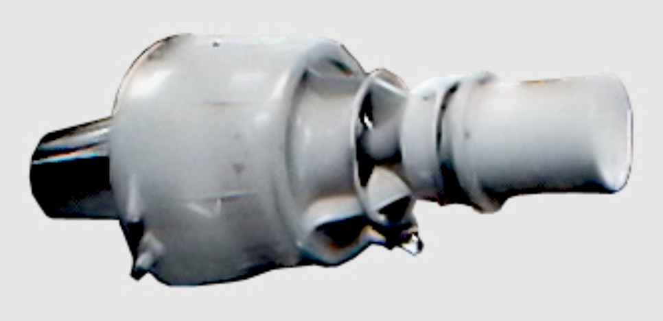
Based on the gas generator section of the Microturbo Emeraude starter and APU for Concorde prototypes, the Eclair is an ultra-small single-shaft turbojet designed to power pilot-less drones and for use in sailplanes.
The engine is also capable of in-flight starting to provide powered flight in an emergency. Initial installation was in the Fauvel Aile Volante AV 45-01R single-seat tailless self-launching sailplane which first flew with the Eclair 012-01 in late 1967.
Height: 12.7 in / 312 mm Width, including accessories: 19.9 in / 501 mm Length overall: 23.9 in / 607 mm Weight: 77 lb / 35 kg TO pwr 47 000 rpm: 176 lb / 80 kg Fuel at TO pwr: 198 lb/hr / 90 kg/hr
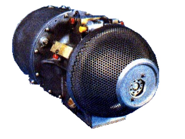
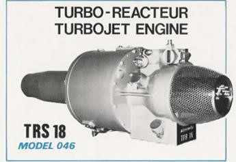
The Microturbo TRS 18 is a small, low thrust turbojet designed and built in France in the 1970s. It was installed on both manned and unmanned aircraft.
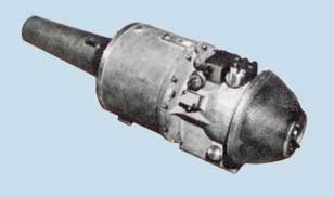
The TRS 18 was originally designed for self-launching motor gliders but was adapted to power conventional ultralight aircraft and unmanned vehicles (RPV). It was originally designed and developed by Sermel, a competitor company to Microturbo which the latter took over in 1971. It is a simple, low thrust, reverse flow single shaft engine with a centrifugal compressor and axial turbine. It is built in three modules: an intake section containing starter and lubrication systems; a centre section with compressor and turbine on ball bearings; and an aft section with the folded combustion chambers and tail-pipe.
Early microjets developed 200 lbs thrust, while the newer TRS 18-1 engine develops 325 lbs thrust with nearly identical in dimension & weight.
It gained its US Federal Aviation Administration type certificate E13CE on 25 May 1976.
TRS 18-046
Variants:
TRS 18-046 Production version, primarily intended for manned applications with full self start provision, oil lubrication and temperature and pressure transducers.
TRS 18-056 Cut down gas generator or core engine version, fuel lubricated and only 62% the weight of the 18-046 version but the same thrust; intended for RPVs.
TRS 18-075 Intended respectively for the Flight Refuelling ASAT target drone. Includes an engine driven alternator and fuel and oil lubrication pumps. Dry weight as 18-046. Take-off thrust increased to 1.15 kN (260 lb st) and maximum continuous thrust to 1.10 kN (247 lb st).
TRS 18-076 Intended for the Meteor-Mirach 100. Includes an engine driven alternator and fuel and oil lubrication pumps. Dry weight as 18-046. Take-off thrust increased to 1.15 kN (260 lb st) and maximum continuous thrust to 1.10 kN (247 lb st).
Microturbo TRS 18-1 Thrust: 325 lbs Max Running Altitude: 30,000 ft. Weight : 84.88 lbs. Length : 27 in. Diameter: 13 in. Fuel Types: Jet A, JP4-JP5 Oil Types: MIL-L-23699 Fuel Consumption (Max Power): 283 lbs./hr.
TRS 18-046 Type: Single shaft centrifugal turbojet. Length: 650 mm (25.59 in) Diameter: 325 mm (12.80 in) wide × 350 mm (13.78 in) high. Dry weight: 37 kg (81.6 lb) dry, basic, no jet pipe. Compressor: Centifugal; one piece with diffuser and straightener vanes. Combustors: Folded, with ten spill type burners. Turbine: Axial. Fuel type: Electric pump. Oil system: Submerged pump in tank on front underside; filter and pressure transducer on upper side. Closed circuit with high pressure supply to rotor and gearbox bearings. Maximum thrust: Take-off 1.10 kN (247 lb st). Maximum continuous 1.00 kN (225 lb st). Specific fuel consumption: 35 mg/N/s (1.24 lb/h/lb st). Maximum altitude: 9000 m
Turbomeca was founded August 29, 1938 by Joseph Szydlowski and André Planiol following their patent of a supercharger in 1937. Hispano-Suiza ordered a demonstrator to equip its 12 Y engine, used among others on the MS 405 C1.
Turbomeca changed rapidly from an artisanal production to an industrial one benefiting from the politics of re-armament. This is shown by the production figures of the following three years: 18 compressor in 1938, 300 in 1939 and 1200 in 1940. Although the factory at Mézières-sur-Seine was only really operational in June 1940, the government advised the move to the south of France due to the German advance. During the same month, Turbomeca had relocated in newly requisitioned workshop in Saint-Pé-de-Bigorre near the Hispano-Suiza engine factory in Tarbes. The buildings were found to be too small and in 1941 a place is bought in Bordes near Pau. Between the autumn of 1941 and June 1942 Turbomeca moved. In November 1942, Szydlowski fled to Switzerland. Between October 1942 and 1944, the production stale and the workforce went from about 300 to about 50.
From 1950, Turbomeca produced the tiny centrifugal flow Palas turbojet, producing 1.6 kN (353 lbf). The Palas was also produced by Blackburn and General Aircraft in the UK and Continental in the USA. From 1957, it manufactured the Bastan turboprop for the Aérospatiale N 262 airliner. Blackburn had a licence for producing other Turbomeca designs.
Rolls-Royce Turbomeca Limited was established in 1968 to develop the Adour jet engine for the Anglo-French SEPECAT Jaguar. The company went on to develop the RTM322 turboshaft, which powers Westland WAH-64, and some models of the AgustaWestland EH101 and NHI NH90.
In 2001 Turbomeca and Rolls-Royce won a $1 billion USD contract to equip 399 German, French and Dutch NH90 helicopters with their RTM322 engines.
SNECMA Group acquired the company in September 2001.
Headquarters: Bordes, France Revenue (2006): € 870 million Employees (2006): 5,178
As of 2012, Turbomeca turbines power civil, parapublic and defence helicopters for all the leading helicopter manufacturers (mainly Eurocopter, but also AgustaWestland, Sikorsky, NHI, Kamov, HAL).
Engines of Microturbo:
Palas SG 18 TRS 18 TRS 25 TRI 40 TRI 60 TRI 80 J403 Cougar Eclair Eclair II Lynx
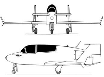
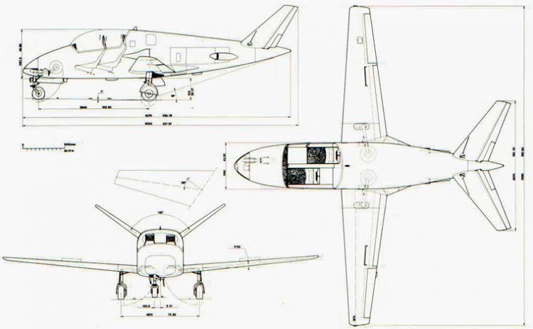
Burt Rutan design VariViggen started when he was a student at Cal Poly (California Polytechnic State University) in the early 1960s. He started building the prototype in his garage in 1968. After four years of work, the aircraft made its first flight 27 February 1972.
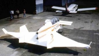
Leo Chagnes built the MicroStar based on plans of the VariViggen over four years.
The wing is styrofoam foam with epoxy coating and the fuselage is spruce and birch plywood. It is powered with 2 TRS18 Microturbo turbojet engines. Microturbo was responsible for the engine, with the completion of the frame, the calculation of the implementation and the centering of the two engines. This installation required a modification of the rear. The increase in surface area required a 20 cm increase.
The air inlets are fiberglass, and the cowling is made of sheet aluminium. The electronics are located just outside the engines, and is accessed by doors. The power units are separated from the airframe by three fire partitions.
The wheels are derived from a Cesna150 and the assembly is retractable via an electric servo coupled with a manual override. The luggage compartment behind the rear seat has been replaced by a 200 lt kerosene fuel tank, additional to two 35 lt tanks housed in the wings.
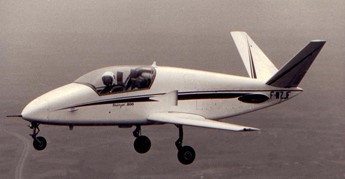
After more than 4 hours running and jumps, Leo Chagnes made the first flight on July 20, 1979.
Burt Rutan flew with Jacques Costes aboard MicroStar on December 19, 1981.
Speed max: 400 km / h Speed cruise: 320 km / h ROC: 6 m / s Stall: 85 km / h TO dist (15 m): 320 m Ceiling: 8000 m Empty weight: 545 kg Max weight: 889 kg Fuel capacity: 271 lt
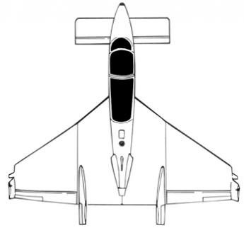
The aim of the Microjet 200 program was to offer economies in military pilot training by use of very small high-performance jet aircraft with comparatively low initial and operating costs.
A team was employed by Société Microturbo to developed this aircraft. The team included Jacques Grangette who was both leader of the team and in charge of development, Claude Fimbel, who conducted the study work and Jules Bernard, in charge of fabrication. Wind tunnel testing was executed at CEAT, Institut de Mécanique des Fluides de Lille (IMFL) for spin, and ONERA for flutter analysis. Microjet was founded to develop and assemble Microjet 200 B two-seat very light trainer powered by two Microturbo turbojet engines (first flown 1980). Many components built by Marmande Aeronautique, later building complete pre-production aircraft.
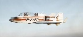
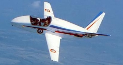
The Microjet 200 is a side-by-side two-seater, initialy powered by two Microturbo TRS18-046, each rated at 1.08 kN (243 lb st.).
The Microjet 200 made its first flight from Toulouse-Blagnac on 24 June 1980. The aircraft flew for 40 minutes without problem, at an altitude of 1000 metres and a speed of 220 km/hr. Jacques Grangette was at the controls.
Propotype # 1 – FWZJF Built entirely of wood. Only a few parts require special forming were made out of resin.
It still exists, and is kept in reserve a hangar flying club Marmande.
Prototype Wingspan: 7.38 m Length: 6.05 m Height: 1.80 m Wing area: 6.12 m² Empty weight: 600 kg Max weight 930/1050 kg Stall: 118 Km / h Max cruise: 463 km / h
Microjet 200b – N ° 01 F- WDMT, it was the first copy of pre-series, any metal . This aircraft was damaged by Wed, March 13th, 1985 in the Bay of Saint- Brieuc, killing its pilot Domnique Monguillot. A trawler at the time had recovered some pieces of the plane’s body. Dominique has never been found.
Microjet 200b – No. 02 F- WDMX, Second pre-series made its first flight January 5, 1985. Built by Marmande Aerospace. It was characterized by the presence of hardpoint on the wings for the carriage of weapons.
Microjet 200b – N ° 03 F- WDMT, Third pre-series aircraft, which carried the registration of the first 200b. Made its first flight Nov. 4, 1986. This unit was also built by Marmande Aerospace.
Alan Arnold Griffith published a seminal paper in 1926, An Aerodynamic Theory of Turbine Design, that for the first time clearly demonstrated that a gas turbine could be used as a practical, and even desirable, aircraft powerplant. The paper started by demonstrating that existing axial compressor designs were “flying stalled” due to their use of flat blades, and that dramatic improvements could be made by using aerofoil designs instead, improvements that made a gas turbine practical. It went on to outline a complete compressor and turbine design, using the extra exhaust power to drive a second turbine that would power a propeller. In today’s terminology the design was a turboprop. In order to prove the design, Griffith and several other engineers at the Royal Aircraft Establishment built a testbed example of the compressor in 1928 known as Anne, the machinery being built for them by Fraser and Chalmers. After Anne’s successful testing they planned to follow this up with a complete engine known as Betty.
In 1929 Frank Whittle’s thesis on pure jet engines was published, and sent to Griffith for comment. After pointing out an error in Whittle’s mathematics, he went on to deride the entire concept, saying that the centrifugal compressor Whittle used would be impractical for aircraft use due to its large frontal area, and that the use of the jet exhaust directly for power would be extremely inefficient. Whittle was distraught, but was convinced that he should patent the idea anyway. Five years later a group of investors persuaded him to start work on what would be the first working British jet engine.
Griffith continued development of his own concepts, eventually developing an advanced compressor design using two contra-rotating stages that improved efficiency. His partner, Hayne Constant, started discussions in 1937 with Manchester-based Metrovick, a maker of steam turbines, to produce the new machinery. Incidentally, Metrovick had recently merged with British Thomson-Houston, another turbine builder who were supporting Whittle’s efforts.
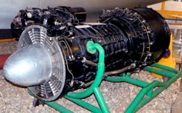
A contract for development work was eventually given by the Air Ministry the next year, and work on Betty, also known as the B.10, started. In 1939 the team, including Metrovick engineers led by David Smith, started work on a flyable design, the F.1. Compared to the centrifugal-flow Whittle designs, the F.1 was extremely advanced, using a nine-stage axial compressor, annular combustion chamber, and a two-stage turbine (the second driving a propeller).
In April 1939, Whittle gave a startling demonstration of his experimental engine, the WU, running it for 20 minutes at high power. This led to a rash of contracts to build a production quality design suitable for aircraft use. Development had just started on the F.1 when Whittle started building his W.1 design, planning to install one for flight in the Gloster E.28/39 the next year. Smith decided to end development of the F.1 and move on to a pure-jet instead, starting work on the otherwise similar F.2, Freda, in July 1940.
Development of the F.2 progressed rapidly, and the engine ran for the first time in November 1941. By this point there were a number of engines in development based on the Whittle concept, but the F.2 looked considerably more capable than any of them. Flyable versions, the F.2/1, received its test rating in 1942 and were flown on an Avro Lancaster test-bed (the first prototype Lancaster, s/n BT308) on 29 June 1943, mounted in the rear fuselage. Production quality versions were tested on the F.9/40M (Gloster Meteor) s/n DG204/G which made its first flight on November 13, 1943. These were installed in Messerschmitt Me 262 type underslung nacelles.
As expected, the engines were more powerful than the Whittle design, first delivering 1,800 lbf (8 kN) but soon scaling up to well over 2,000 lbf (8.9 kN). Around this time, the Whittle W.2B was developing 1,600 lbf (7.11 kN). However, the engine suffered from a number of problems that cast doubts on its reliability. These were primarily due to hot spots building up on the turbine bearing and combustion chamber. The latter, in turn, caused warping and fractures of the turbine inlet nozzles.
To address these problems, in August 1942 a minor redesign delivered the F.2/2, which changed the turbine material from Rex 75 to Nimonic 75, and lengthened the combustion chamber by 6 inches (150 mm). Thrust was improved to 2,400 lbf (11,000 N) static, but the problems with overheating remained.
Another attempt to solve the overheating problems resulted in the more highly modified F.2/3 during 1943. This version replaced the original annular combustion chamber with can-type burners like those on the Whittle designs. This appears to have solved the problems, raising the thrust to 2,700 lbf (12,000 N) in the process. However, by this time it was decided to move on to a much more powerful version of the engine.
Development of the F.2 continued on a version using a ten-stage compressor for additional airflow driven by a single stage turbine. The new F.2/4 – the Beryl – initially developed 3,250 lbf (14.45 kN) and was test flown in Avro Lancaster Mk.II s/n LL735 before being installed in the Saunders-Roe SR.A/1 flying boat fighter. Thrust had already improved to 3,850 lbf (17.1 kN) for the third prototype, and eventually settled at 4,000 lbf (17.8 kN). In comparison, the Derwent developed only 10.9 kN in its ultimate form; making the Beryl one of the most powerful engines of the era. Development of the SR.A/1 ended in 1947, ending development of the Beryl along with it. Nevertheless a Beryl from the SR.A/1 prototype was removed and used by Donald Campbell for early runs in his famous 1955 Bluebird K7 hydroplane in which he set seven water speed records between 1955 and 1964.
In 1942 MV started work on thrust augmentation. The resulting Metropolitan-Vickers F.3 was the first British turbofan engine to be designed, built and tested. Indeed, it could be said that the F.3 was also the very first 3-shaft jet engine to be built, although the configuration was completely different to that of the much later Rolls-Royce RB211 turbofan series, since the fan was located at the rear of the engine, not unlike that of the General Electric CJ805-23. Using a stock F.2/2, MV added a separate module to the rear of the engine (directly behind the HP turbine) which comprised contra-rotating LP turbines attached to two contra-rotating fans. Apart from the first stage nozzle guide vanes, the LP turbine was completely statorless, with four consecutive rotor stages. Rotors 1 and 3 drove the front fan clockwise (viewed from front), whereas the rear fan was driven anticlockwise by rotors 2 and 4. Although the front fan had inlet guide vanes, there were no vanes between the contra-rotating fan rotors or, downstream, any exit guide vanes. The core and bypass streams exhausted through separate coaxial propelling nozzles.
The project was generally successful, raising static thrust from around 2,400 lbf (11,000 N) to 4,000 lbf (18 kN). More importantly, specific fuel consumption fell from 1.05 to 0.65 lb/hr/lbf, which was the true aim of the project. The weight increase for all the extra turbomachinery and ducting was fairly significant, however. A bonus was that the team noticed that the cold air from the fan mixed with the hot exhaust from the gas generator, resulted in a marked decrease in noise levels, the first time such an effect had been recorded (it was re-discovered during a major NASA project in the 1960s).
Although the F.3 progressed nicely, development was curtailed by the pressures of war. When the war ended the F.2/2 was no longer current, so some of the ideas were applied to the more up-to-date F.2/4 to produce the Metropolitan-Vickers F.5 propfan.
Following on where the F.3 left off, the F.5 was a version of the F.2/4 with an open rotor (unducted) thrust augmenter added to the end of the jet pipe, somewhat remote from the HP turbine The 5 ft 6 in diameter fixed pitch propellers, which contra-rotated, were driven by a 4-stage statorless LP turbine unit, similar to that of the F.3. The General Electric GE36 UDF demonstrator of the 1980s also used a similar LP turbine arrangement, albeit with many more stages. In addition, the GE36 propellers were variable pitch. With both propfans, the LP turbine arrangement enabled the propellers to rotate at optimum speed, without the need for a reduction gearbox.
Static thrust increased from the 3500lbf of the F.2/2 to in excess of 4,710 lbf (21,000 N), with a corresponding reduction in specific fuel consumption. Relative to the parent turbojet, the weight increase for this propfan configuration was about 26%, compared to 53% for the F.3 turbofan. Unfortunately, the company cancelled development when they sold their gas turbine business to Armstrong Siddeley in 1946.
Development of the F.2 ended in 1944. Development of the basic concept continued, however, eventually leading to the considerably larger F.9 Sapphire. However, in 1947, Metrovick left jet engine production and their design team moved to Armstrong Siddeley. The Sapphire matured into a successful design, initially besting the power of its Rolls-Royce contemporary, the Avon. Design features of the Metrovick line were worked into Armstrong Siddeley’s own line of axial compressor turboprops, although Armstrong Siddeley dropped Metrovick’s use of gemstone names for their engines in favour of continuing with animal names, in particular snakes.