The M.5 Sparrowhawk prototype G-ADNL survived the war. Air racing enthusiast Fred Dunkerley acquired the Sparrowhawk and in 1950 he sent it to F.G.Miles at Redhill in Surrey, with instructions that it be rebuilt as a jet-powered racer. Fred Miles conceived the idea of replacing the M.5 140 hp high compression Gipsy Major with two Turbomeca Palas turbojets, each developing 330 lb maximum thrust (equivalent to about 550 hp in total).
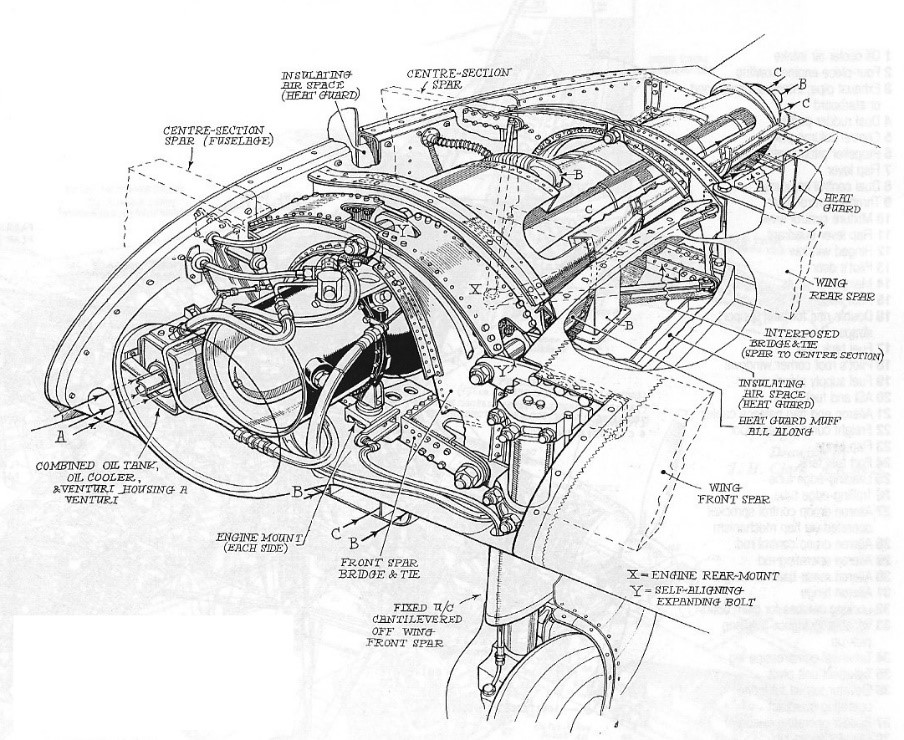
With a length of 35in and a diameter of 16in, for an individual weight of 160 lb, the Palas units required new twin metal¬ sparred inner wing attachments to the fuselage centre section for their upper wing root housing. Designer, aerody¬namicist, stress engineer and flight test observer Grahame Gates, who was brought in to assist George Miles, recalls that the Sparrowjet centre section attachments and engine mountings required some complex engineering. This included curved compression mem¬bers with a pin joint above each engine centreline, and the rear spar straddling the hot tailpipe. Being completely buried within the wing chord, the little Palas engines also needed short stainless steel exhaust channels to protect the adjacent wing structure.
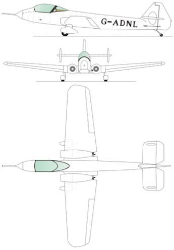
A completely new single seat cockpit and forward fuselage section was also required, resulting in an increase in length of nearly 7ft to 29ft 7in, includ¬ing a new and bigger tail assembly to balance the additional side area of the longer nose. Two small fins near the tailplane tips were also added solely as mass balance fairings.
While the original Hawk wooden wings with their ancient Clark YH aero¬foil sections were retained, extensive modifications were required to incorpo¬rate a 38gal fuel tank in each for the turbojets. The wings’ twin ¬sparred structure also had to be rein¬forced and re covered with thicker ply skins to cope with the increased air¬speeds, and their stiffness was further improved when 18in were clipped from each wingtip during initial flight development.
Squared off tips, with no decrease in aileron span, had been schemed as a means of achieving an increase in lateral control effec¬tiveness, and of reducing associated stick forces. Their planned removal, however, was delayed until after initial flight trials, to retain lighter wing load¬ing and docile handling in the early stages of development. Overall wingspan was still 7in more than the Sparrowhawk’s original 28ft, because of the additional wing root engine bays.
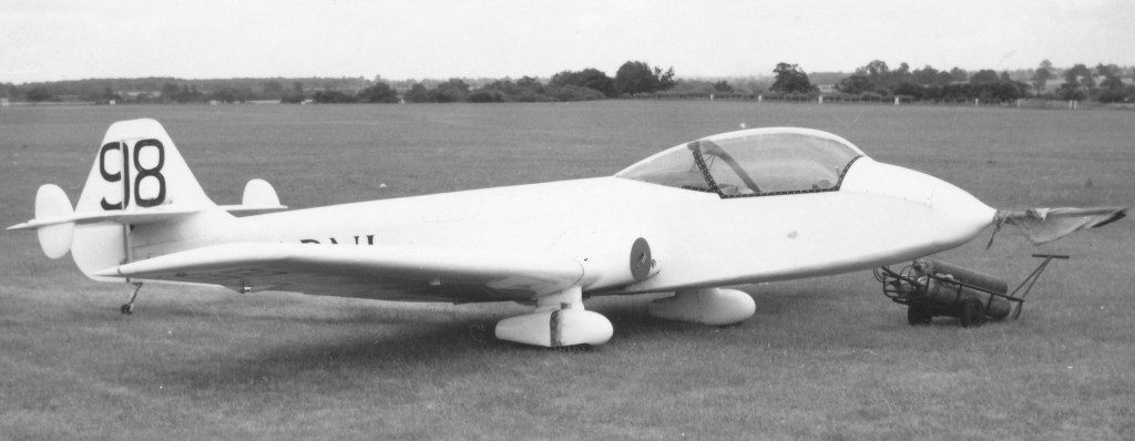
With no propeller clearance problems, shortened, spatted Magister type mainwheel undercar¬riage oleos with stub axles instead of alloy forks, and Goodyear tyres and brakes, could be used. Although these brought the Palas tailpipes close to the ground, no problems were reported from surface erosion. The two engines increased empty weight by more than 500 lb to 1,578 lb, although the maximum take off weight went up by only 200 lb, to 2,400 lb.
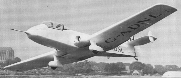
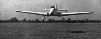
All of these changes took time, and were further complicated by accompa¬nying budget overruns, as well as the transfer of F.G. Miles’s activities from Redhill to Shoreham in 1952. It was not until December 14, 1953, after three year’s work, that G.H. Miles made the first flight of the redesignated M.77 Sparrowjet (c/n FGM 77/1006) at Shoreham. Originally flown under B conditions as G 35 2, it soon reverted to its original civil registration, G ADNL, plus racing number 99 on the new broad chord fin and rudder.
Sparrowjet G-ADNL 2 July 1957 Coventry
Few problems were encountered dur¬ing Sparrowjet flight development, which was shared by G.H. and Miles test/sales pilot Ian Forbes. The Sparrow¬jet’s inaugural flight also marked its initial pilot’s first jet experience, a distinction which Fred Dunkerley shared when he had his baptism on type on Whit Monday, 1954. It was evident that, while the cruis¬ing and maximum speeds of the Sparrowhawk had been increased by over 50 mph, its pleasant flying qualities and docile low speed handling had been retained.
In the C of A, the Ministry of Civil Aviation and the Air Regis¬tration Board (ARB) had imposed a restriction of 31,400 rpm maximum continuous power on the Palas tur¬bojets, instead of their rated 33,800 rpm, which was permitted only for take off or emergencies. This had the effect of reducing the Sparrowjet’s design maximum speed performance of 240 mph to a revised handicap estimate of 227 mph.
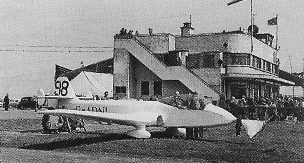
Engine start¬ing was normally via high pressure air from a large ground cylinder to spin the centrifugal compressor up to light up rpm. This system saved the weight and complication of integral electric starters, but effectively ruled out off base operation without the necessary ground equip¬ment.
At Yeadon 21 May 1956 when it won the SBAC Challenge Cup
G-ADNL usually operated from the airfield Barton, participating in many races, including:
SBAC Challenge Cup in 1956 at an average speed of 197 mph [316 km / h] King’s Cup Race July 13, 1957, at an average speed of 228 mph [366 km / h]
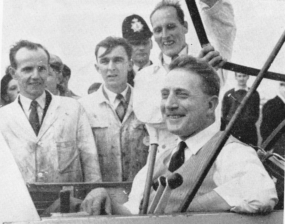
1957 King’s Cup winner, flown by Fred Dunkerley immediately after landing
The M.77 SparrowJet was destroyed in a fire at a hangar at RAF Upavon in 1964.
Engines: two Turbomeca Palas turbojets, 330 lb max thrust each Wingspan: 8.49 m Total length: 9.40 m Wing area: 14,50 m² Empty weight: 717 Kg Maximum weight: 1090 Kg Max speed: 368 Km / h Range: 432 Km Climb rate: 640 m / min Wing loading: 75 Kg / m²
Designed to meet Specification E.24/43, which called for an aeroplane capable of flying more than twice as fast as any that had previously flown in level flight.
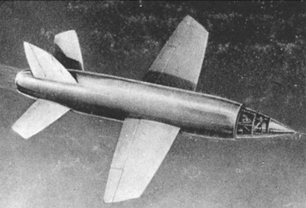
The Miles company began work on the M.52 in 1943, at a time when knowledge of high-speed aerodynamics was strictly limited. As the project was masked in secrecy, Miles set up its own foundry for the production of the necessary metal components and also built a high-speed wind tunnel. The Miles M.52 used ultra thin, bi convex wings, flight tested on the Miles ‘Gillette Falcon’, and other advanced features such as an annular air intake, all moving tailplane. A full-scale wooden mock-up of this unique high-speed wing design was built and tested on a Miles Falcon light aircraft in 1944.
The design featured a bullet-like fuselage of circular section, 1.5m in diameter, constructed of high-tensile steel with an alloy covering. The powerplant, a Power Jets W.2/700, was centrally mounted and fed by an annular air intake, the cockpit forming a centre cone. The whole cockpit cone, in which the pilot sat semi-reclined, could be detached in an emergency by firing small cordite charges; the pilot would then bale out normally when the capsule reached a lower altitude. The M.52 was fitted with biconvex section wings, mounted at mid-point on the fuselage. As design work progressed, various refinements were incorporated. Split flaps were fitted, together with an all-moving tailplane. The addition of rudimentary afterburners in the form of combustion cans situated at the rear of the engine duct was calculated to produce much greater thrust at supersonic speed.
The very thin wing section meant that the undercarriage had to be positioned to retract into the fuselage.
Detailed design work on the M.52 was 90 per cent complete by the beginning of 1946, and the jigs were ready for the assembly of three planned prototypes. No snags were envisaged in construction, and it was expected that the first M.52 would fly within six to eight months. Then, in February 1946, quite without warning, F.G.Miles received word from the Director General of Scientific Research at the Ministry of Aircraft Production, Sir Ben Lockspeiser, that all work on the M.52 project was to cease at once.
Secrecy surrounded the cancellation of the M.52, just as it had surrounded its design, and it was not until September 1946 that the British public were made aware that their aircraft industry had been within sight of flying the world’s first supersonic aircraft. The stated reason behind the decision to cancel the M.52 was that it had already been decided, early in 1946, to carry out a supersonic research programme with the aid of unmanned models developed by Vickers Ltd, the department responsible was headed by Dr Barnes Wallis. Between May 1947 and October 1948 eight rocket-powered models were launched, only three of which were successful. In each failure (apart from the first attempted launch when the Mosquito launch aircraft got out of control in cloud and the model broke away) it was the rocket motor that failed, not the airframe.
Only a year after the M.52’s cancellation was made public, Major Charles Yeager, US Air Force, had made history’s first supersonic flight in the rocket-powered Bell X-1 research aircraft.
Engine: 1 x 2000 lb / 907kg Power Jets W.2/700 turbojet engine, with afterburning 4100 lb / 1860 kg st Wingspan: 8.20 m / 26 ft 11 in Length: 10.20 m / 33 ft 6 in Design max take-off weight: 3715 kg / 8190 lb Wing area: 143 sq.ft / 13.28 sq.m Max design speed: 1,000 mph / 1,609 km/h) at 36,000 ft / 11,000 m Ceiling: 15250 m / 50050 ft Crew: 1
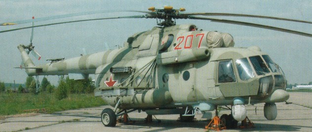
Design began in 1983 of the Mi-38 medium transport helicopter with a model shown at the 1989 Paris Air Show, when the aircraft was at the mockup stage. Modifications in evidence by 1993 included fixed landing gear with wider track and a reduced base.
Of conventional pod and boom configuration, the power plant is above the cabin. A six-blade main rotor has considerable non-linear twist and swept tips. The main rotor has hydraulic drag dampers, a single lubrication point at the driveshaft; and rotor brake standard. A Krasny Oktyabr transmission, comprising main, intermediate and tail gearboxes and tail rotor drive shaft takes the engine input of 19,017 rpm. Two independent two-blade tail rotors, set as narrow X on same shaft are fitted, with a sweptback fin/tail rotor mounting, and small horizontal stabiliser. Control is fly-by-wire, with manual back-up.
The composites main and tail rotors are by Kazan, with a low-profile titanium main rotor head, with elastomeric bearings, built by Stupino. The fuselage, mainly composites, is built by Kazan. Landing gear is a fixed tricycle type: single wheel on each main unit; oleo-pneumatic shock absorbers; twin, self-centring nosewheels; low-pressure tyres; optional pontoons for emergency use in overwater missions. Main tyres 950mm diameter, pressure 5.88 bar; nose tyres 600mm diameter, pressure 4.90 bar.
Those helicopters for CIS customers powered by two Klimov TVA-3000 (TV7-117 derivative) turboshafts, each rated at 1,838kW for T-O; single-engine rating 2,610kW and transmission rated for same power. Optional are two 2,461kW P&WC PW127 rurboshafts, which are also available, in PW127T/S form, for Western customers. Power plant above cabin, to rear of main reduction gear; air intakes and filters in sides of cowling. Bag fuel tanks beneath floor of main cabin; provision for external auxiliary fuel tanks. Liquid petroleum gas fuel planned as alternative to aviation kerosene.
Crew of two on flight deck, separated from main cabin by compartment for majority of avionics; single-pilot operation possible for cargo missions. Lightweight seats for 30 passengers as alternative to unobstructed hold for 5,000kg freight. Ambulance and air survey versions planned. Passenger door, forward, port; freight door, forward, starboard; cargo ramp at rear; hatch in cabin floor, under main rotor driveshaft, for tactical/emergency cargo airdrop and for cargo sling attachment; optional windows for survey cameras in place of hatch. Provision for hoist over portside door, remotely controlled, hydraulically actuated rear cargo ramp, powered hoist on overhead rails in cabin, and roller conveyor system in cabin floor and ramp.
Air conditioning by compressor bleed air, or APU on ground, maintains temperature of not more than 25 degrees C on flight deck in outside temperature of 40 degrees C, and not less than 15 degrees C on flight deck and in main cabin in outside temperature of –50 degrees C. Three independent hydraulic systems; any one able to maintain control of helicopter in emergency. Electrical system has three independent generators, two at 12kW DC and one 60kW AC; optional fourth generator 40 or 60kW AC; two batteries; electric rotor blade de-icing, main and tail. Independent fuel system for each engine, with automatic crossfeed; forward part of cowling houses VD-100 APU, hydraulic, air conditioning, electrical and other system components.
A preset flight control system allows full autopilot, autohover and automatic landing. Avionics controlled by large central computer, linked also to automatic nav system with Doppler, ILS, satellite nav system, main radar, autostabilisation system and automatic radio compass.
Instrumentation: Six colour CRTs for use in flight and by servicing personnel on ground. Equipment monitoring, failure warning and damage control system. Closed-circuit TV for monitoring cargo loading and slung loads.
Under December 1992 agreement, Eurocopter will integrate flight deck, avionics and passenger systems, and will adapt Mi-38 for international market; Euromil joint stock company established September 1994 to advance collaboration, adding Kazan production plant (as main manufacturing and final assembly centre); funding for Euromil granted in October 1994 by European Bank for Reconstruction and Development. Sextant and Pratt & Whitney Canada added as risk-sharing parties for avionics and engine. Funding by Russian Ministry for Defence Industries 1996. Mi-38 rotor blades began test flying on an Mi-17 in early 2001.
By 1997, Euromil was anticipating first flight in 1999 and start of production two years later, following FAR Pt 29 certification. However, contracts for completion of demonstrator not signed until 18 August 1999, following unilateral decision of Euromil board in December 1998 to launch programme and fly demonstrator at Kazan in 2001, although this subsequently slipped to 2002 and then to mid-2003. Demonstrator (PT-1) is third airframe, following test articles at Mil Moscow and Kazan. Four further prototypes to follow, including two for static testing.
Mi-38 Engine: 2 x Klimov TVA-3000 Instant pwr: 1838 kW Main rotor diameter: 21.1m Length without rotors: 19.95m Height: 5.13m Width: 4.9m Max take-off weight: 15600kg Empty weight: 8300kg Max speed: 290km/h / 148 kts Cruising speed: 275km/h Service ceiling: 5200m / 21,325 ft Hovering ceiling: 2500m HOGE: 8200 ft Range with max take-off weight and with 3500kg payload: 800km Payload: 6000kg, Crew: 2 Pax: 30
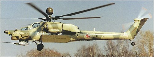
The Mi-28 is a tandem two-seat, twin-turbine anti-armour helicopter, NATO name Havoc. Design started in 1980 under Marat N Tishchenko, the first of two flying Mi-28 prototypes (012) flew on 10 November 1982.
Each prototype different with the first and second (022) having upward-pointing exhaust diffusers and fixed undernose fairing for electro-optic equipment. The first also had conventional three-blade tail rotor, the second replaced this with the definitive “Delta-H” configuration. The first two prototypes were powered with 1,434kW TV3-117BM engines and VR-28 gearbox.
The three prototypes had a conventional three-bladed tail rotor but was replaced by a ‘delta 3’ x-configured rotor comprising two independent two-bladed propellers mounted on the same shaft. The gunner, seated in a heavily-armoured front cockpit ahead of the pilot, controls a 30mm cannon normally used on ground vehicles. This is mounted under the nose, which contains a low light level TV and FLIR night control systems. Stub wings, each fitted with two hardpoints, can carry AT-6 ‘Spiral’ radio-guided ATMs, UV-20 pods, or fuel tanks. Infra-red suppressors and decoy dispensers are also fitted to the ‘Havoc’.
The third and fourth aircraft built were of Mi-28A (Type 280) basic version.
The first Mi-28A (032) introduced the definitive downward-pointing exhaust suppressors and flew in January 1988, with the second Mi-28A prototype (042) demonstrated at Moscow in 1992 representing the intended production configuration. It had the definitive moving E-O sensor turret undernose, downward-pointing exhaust diffusers and wingtip electronics/chaff dispenser pods. In emergencies an inflatable crew chute is deployed beneath the door sills. The fuel tanks of the ‘Havoc’ are self-sealing and fire retardant.
Mi-28NE
Flying controls are hydraulically powered mechanical type with the horizontal stabiliser linked to the collective, and controls for the pilot only.
The five-blade main rotor blades have very cambered high-lift section and sweptback tip leading edge. A full-span upswept tab is on the trailing-edge of each blade. Structure comprises numerically controlled, spirally wound glass fibre D-spar, blade pockets of Kevlar-like material with Nomex-like honeycomb core, and titanium erosion snip on the leading-edge. Each blade has single elastomeric root bearing, mechanical droop stop and hydraulic drag damper. A four-blade GFRP tail rotor with elastomeric bearings for flapping is fitted. A rotor brake lever is on the starboard side of the cockpit. A machined titanium main rotor head with elastomeric bearings, requires no lubrication. Power output shafts from the engines drive the main gearbox from each side, and a tail rotor gearbox, at the base of the tail pylon, is driven by an aluminium alloy shaft inside a composites duct on top of the tailboom. Sweptback mid-mounted wings have a light alloy primary box structure, leading- and trailing-edges of composites, and no wing movable surfaces. There is provision for countermeasures pods on each wingtip, housing chaff/flare dispensers and sensors. The light alloy semi-monocoque fuselage has titanium armour around the cockpits and vulnerable areas. A composites access door is aft of the wing on port side. The swept fin has a light alloy primary box structure, composites leading- and trailing-edges, and a cooling air intake at the base of the fin leading-edge, and exhaust at the top of the trailing-edge. There is a two-position composites horizontal stabiliser.
Landing gear is a non-retractable, tailwheel type, with a single wheel on each unit. Mainwheel tyres size 720×320, pressure 5.40 bar; castoring tailwheel with tyre size 480×200.
Power is from two Klimov TV3-117VMA turboshafts, each 1,636kW, in pod above each wingroot; three jetpipes inside downward-deflected composites nozzle fairing on each side of third prototype shown in Paris 1989; upward deflecting type also tested. Deflectors for dust and foreign objects forward of air intakes, which are de-iced by engine bleed air. The internal fuel capacity is 1,720 litres. Provision for four external fuel tanks on underwing pylons.
The navigator/gunner is in the front cockpit, the pilot behind, on an elevated seat, with a transverse armoured bulkhead between. The flat non-glint tinted transparencies are of armoured glass. A navigator/gunner’s door is on the port side, and pilot’s door on the starboard side.
The cockpits air conditioned and pressurised by engine bleed air. Duplicated hydraulic systems, pressure 152 bar are fitted, and a 208V AC electrical system is supplied by two generators on the accessory section of the main gearbox, ensuring continued supply during autorotation. A low-airspeed system is standard, giving speed and drift via main rotor blade-tip pitot tubes at -50 to +70km/h in forward flight. Main and tail rotor blades are electrically de-iced. An Ivchenko AI-9V APU in the rear of the main pylon structure supplies compressed air for engine starting and to drive a small turbine for preflight ground checks.
A radio for missile guidance is in the nose radome. Daylight optical weapons sight and laser range-finder are in a gyrostabilised and double-glazed nose turret above gun. A wiper on the outer glass protects the inner optically flat panel.
Two fixed IR sensors on the initial basic production Mi-28; IR suppressors, radar and laser warning receivers standard. Mi-28N has integrated Vitebsk DASS with Pastel RWR, Mak IR warning system, Platan jammer and UV-26 flare dispensers.
Armament is one 2A42 30mm turret-mounted gun (with 250 rounds in side-mounted boxes) in NPPU-28 mount at nose, able to rotate 110 degrees, elevate 13 degrees and depress 40 degrees. The maximum rate of fire is 900 rds/min air-to-air and air-to ground. The two pylons under each stub-wing, each have a capacity of 480kg. The main 2A42 gun is fired and guided weapons launched normally only from front cockpit. Unguided rockets are fired from both cockpits. (When fixed, the gun can also be fired from rear cockpit.)
A small-scale pre-series production was planned, but not initiated, by Rostvertol, Rostov-on-Don, which stated in mid-2001 that it was ready to begin series production.
The Mi-28 was scheduled to enter full service with the CIS forces in 1992, but lost out to the Kamov Ka-50.
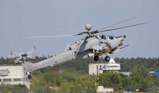
The Mi-28N (Nochnoy: Night) added night/all-weather operating capability. Russian Army funding was announced in January 1994 and a demonstrator (014) was modified from the first Mi-28 prototype (012). The first hover was on 14 November 1995, and formal roll-out on 16 August 1996. The first flight was on 30 April 1997. The Mi-28N is equipped with a mast-mounted 360 degree scan millimetre wave Kinzhal V or Arbalet radar (pod soon enlarged in vertical plane), an FLIR ball beneath missile-guidance nose radome and above new shuttered turret for optical/laser sensors, including Zenit low-light-level TV. The cockpit has EFIS. New composites rotor with sweptback blade tips added later. The Mi-28N introduced uprated VR-29 transmission and IKBO integrated flight/weapon aiming system, with automatic terrain-following and automatic target search, detection, identification and (in formations of Mi-28Ns) allocation; Ramenskoye Breo-28N mission control system. The Mi-28N can carry the Igla (SA-16 ‘Gimlet’) AAM and new-generation ASMs.
Prototype Mi-28N ‘014’ first flight 30 April 1997, Panki, near Moscow.
Total of five trials Mi-28Ns were to be built by Rostvertol; TV3-117VMA engines initially, but 1,839kW Klimov VK-2500s to be installed later. A second helicopter was funded jointly by Rostvertol and Southwest Sberbank.
Mi-28NE
The Mi-28NEh (Nochnoy, Ehksport: Night, Export) version was offered to South Korea in 2000, and evaluated by Swedish Army in 2001 against Boeing AH-64 Apache and Eurocopter Tiger.
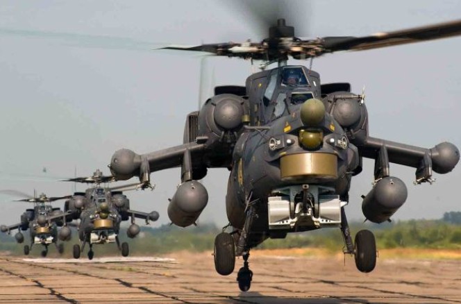
The Mi-28NEh is of conventional gunship configuration, with two crew in stepped cockpits. The original three-blade tail rotor was superseded by a low noise ‘scissors’ or “Delta-H” type comprising of two independent two-blade rotors set as narrow X (35 deg/145 deg) on the same shaft with self-lubricating bearings, the resulting flapping freedom relieves flight loads. Agility is enhanced by doubling hinge offset of the main rotor blades compared with the Mi-24. The crew compartments are protected by titanium and ceramic armour and armoured glass transparencies. The new composites main rotor can withstand a hit from a round of up to 30mm calibre. Multiple self-sealing fuel tanks in the centre-fuselage are enclosed in a composite second skin, outside the metal fuselage skin. Energy absorbing seats and landing gear protect the crew in crash landings at descent rate of 12m/s. The crew doors are rearward-hinged, to open quickly and remain open in emergency. Parachutes are mandatory for Russian Federation and Associated States (CIS) military helicopter aircrew, but no provision for rotor separation. A port-side door, aft of wing, provides access to an avionics compartment large enough to permit combat rescue of two or three persons, although it lacks windows, heating and ventilation.
A hand crank, inserted into the end of each stub-wing, enables stores of up to 500kg to be winched on to pylons without hoists or ground equipment. The main rotor shaft has 5 degrees of forward tilt, providing tail rotor clearance. The transmission is capable of running without oil for 20 to 30 minutes at the main rotor rpm of 242. With main rotor blades and wings removed, the helicopter is air-transportable in an An-22 or Il-76 freighter.
Mi-28N development cost US$150 million (2000) and unit cost approximately US$15 million to US$16 million (2002).
Mi-28 Engines: 2 x Klimov TV3-117VM turboshaft, 1620kW Main rotor diameter: 17.2m Length with rotors turning: 21.6m Height: 3.82m Max take-off weight: 11200kg Empty weight: 7000kg Fuel: 1337kg Max speed: 300km/h Cruising speed: 270km/h Rate of climb: 13.6m/s Service ceiling: 5800m Range with max fuel: 460km HIGE: 19,025 ft HOGE: 11,810 ft Crew: 2
Mi-28N Engines: 2 x Klimov TV3-117VMA turboshafts, 1,863kW Main rotor diameter: 17.20m Fuselage length with a cannon: 17.01m Height: 3.82m Max take-off weight: 11700kg Max speed: 320km/h Cruising speed: 270km/h Hovering ceiling: 3600m Range with 10500kg take-off weight: 500km Range with max fuel: 1000km Armament: 1 x 30mm cannon, 16 x “Shturm” or “Ataka” anti-tank missiles or 8 x “Igla-V” AA missiles Crew: 2
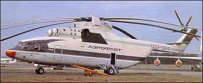
Designed to provide Aeroflot with a heavylift helicopter to assist in the exploitation of undeveloped regions, this aircraft began life in the early 1970s (initially as Mi-6M), as soon as it became clear that the V-12 was not going to fulfil this role. It required the design and development of a completely new rotor and transmission system, plus the need to meet an official requirement that the aircraft’s empty weight should be only half that of its maximum take-off weight, meant that it was not until 14 December 1977 that the V-26 prototype achieved its first hovering flight. NATO name Halo.
Weight has been saved by in-house design of the main gearbox providing multiple torque paths, GFRP tail rotor blades, titanium main and tail rotor heads, main rotor blades of mixed metal and GFRP, and use of alumimum-lithium alloys in airframe.
Equipped with a rear-loading ramp/doors, the main rotor rpm is 132, and the main rotor spindle is inclined forwards 4 degrees. Flying controls are hydraulically powered cyclic and collective pitch controls actuated by small parallel jacks, with redundant autopilot and stability augmentation system inputs. A fly-by-wire system flight was tested in 1994.
An eight-blade constant-chord main rotor has flapping and drag hinges, droop stops and hydraulic drag dampers. No elastomeric bearings or hinges, each blade has a one-piece tubular steel spar and 26 GFRP aerofoil shape full-chord pockets, honeycomb filled, with ribs and stiffeners and non-removable titanium leading-edge abrasion strip. Blades have moderate twist, taper in thickness toward tip, and are attached to small forged titanium head of unconventional design. Each has ground-adjustable trailing-edge tab. A five-blade constant-chord tail rotor on the starboard side, has GFRP blades and forged titanium head. A conventional transmission, with tail rotor shaft inside cabin roof, all-metal riveted semi-monocoque fuselage with clamshell rear doors, and flattened tail boom undersurface. The engine bay is of titanium for fire protection. All-metal tail surfaces and swept vertical stabiliser/tail rotor support are profiled to produce sideways lift. There is a ground-adjustable variable incidence horizontal stabiliser.
Landing gear is a non-retractable tricycle type with twin wheels on each unit. The steerable nosewheels have tyre size 900×300, and mainwheel tyres size 1,120×450. A retractable tailskid is at the end of the tailboom to permit unrestricted approach to the rear cargo doors. The length of the main legs is adjusted hydraulically to facilitate loading through rear doors and to permit loading on varying surfaces. A device on main gear indicates takeoff weight to flight engineer at lift-off, on panel on shelf to rear of his seat.
Power if from two 8,500kW ZMKB Progress (Soloviev) D-136 free-turbine turboshafts, side by side above cabin, forward of main rotor driveshaft. Air intakes fitted with particle separators to prevent foreign object ingestion, and have both electrical and bleed air anti-icing systems. Above and behind is central oil cooler intake. VR-26 fan-cooled main transmission, rated at 14,914kW, with air intake above rear of engine cowlings. System for synchronising output of engines and maintaining constant rotor rpm; if one engine fails, output of other is increased to maximum power automatically. Independent fuel system for each engine; fuel in eight underfloor rubber tanks, feeding into two header tanks above engines, which permit gravity feed for a period in emergencies; maximum standard internal fuel capacity 12,000 litres; provision for four auxiliary tanks. Mi-26TS normal capacity is 13,020 litres. Two large panels on each side of main rotor mast fairing, aft of engine exhaust outlet, hinge downward as work platforms.
Crew of five on flight deck: pilot (on port side) and co-pilot side by side, tip-up seat between pilots for flight technician, and seats for flight engineer (port) and navigator (starboard) to rear; upgrade proposal revealed in early 2001 involves installation of new avionics and will result in reduction of flight deck crew to three. Four-seat passenger compartment aft of flight deck. Loads in hold include two airborne infantry combat vehicles and a standard 20,000kg ISO container; about 20 tip-up seats along each sidewall of hold; maximum military seating for 90 combat-equipped troops; alternative provisions for 60 stretcher patients and four/five attendants. Heated windscreen, with wipers; four large blistered side windows on flight deck; forward pair swing open slightly outward and rearward. Downward-hinged doors, with integral airstairs, at front of hold on port side, and each side of hold aft of main landing gear units. Hold loaded via downward-hinged lower door, with integral folding ramp, and two clamshell upper doors forming rear wall of hold when closed; doors opened and closed hydraulically, with back-up hand pump for emergency use. Two LG-1500 electric hoists on overhead rails, each with capacity of 2,500kg, enable loads to be transported along cabin; winch for hauling loads, capacity 500kg; roller conveyor in floor and load lashing points throughout hold. Flight deck fully air conditioned.
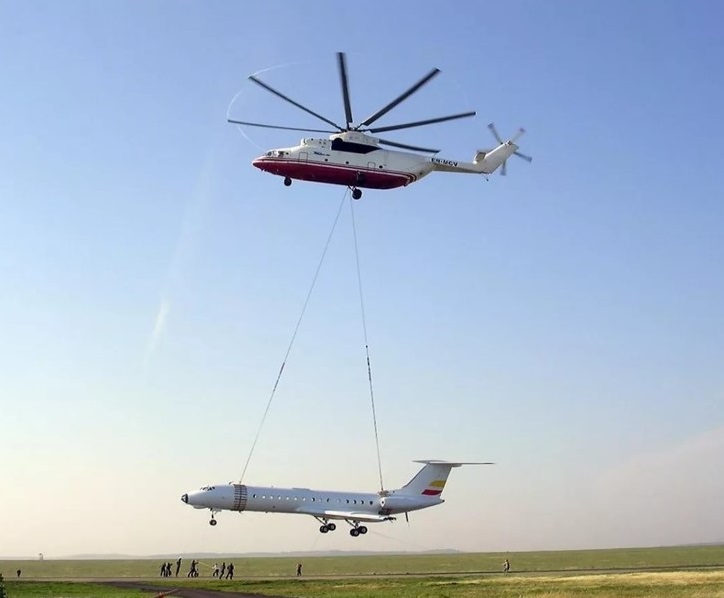
It has a cargo hold 3.20m wide, 3.15m/ 10.25 ft high and 15m/49 ft deep. The maximum payload is 5000kg or 70-100 passengers. The helicopter has a crew of four, with room for an additional handler, and has a full range of navigational electronics and an automatic hover system.
Two main and one emergency hydraulic systems, operating pressure 157 and 206 bar. Electrical system three-phase 200/115V 400Hz; single-phase 115V 400Hz; three-phase, 36V 400Hz; single-phase 36V 400Hz; DC 27V. TA-8V 119kW. APU under flight deck, with intake louvres (forming fuselage skin when closed) and exhaust on starboard side, for engine starting and to supply hydraulic, electrical and air conditioning systems on ground. Electrically heated leading-edge of main and tail rotor blades for anti-icing. Only flight deck pressurised.
Systems include: Radar: Groza 7A813 weather radar in hinged (to starboard) nosecone. Flight: Integrated PKV-26-1 flight/nav system and automatic flight control system, Doppler, map display, HSI, and automatic hover system. Optional GPS. Self-defence: Military versions can have IR jammers and suppressors, IR decoy dispensers and colour-coded identification flare system.
A hatch for a load sling is in the bottom of the fuselage, in line with the main rotor shaft, the sling cable attached to internal winching gear. Closed-circuit TV cameras observe slung payloads. Specialised versions can utilise firefighting equipment.
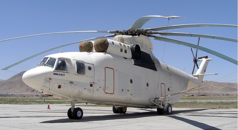
Mi-26T
The first production aircraft rolled out in October 1980 and one of several prototype or preproduction Mi-26s (SSSR-06141) was displayed at the 1981 Paris Air Show. In-field evaluation began early 1982 and the type was fully operational in 1983. The production model carries a crew of five, and up to 85 combat-equipped troops, or two airborne infantry combat vehicles. More than 50 were in service in 1987.
On 3 February 1982, as just one of a string of new records established by the Mi-26, a “standard production” Mi 26 lifted a total mass (helicopter plus payload) of 56768.8kg to a height of 2000m. Also in February, 1982, set several load to height records, including lifting 25,000 kg (55,115 lbs) to 4,100 metres (13,451 ft).
In a series of flights with different crews the helicopter set various records; 25,000 kg / 55,115 lb to 4100m / 13,451 ft 20,000 kg / 44,092 lb to 4600m / 15,092 ft 15,000 kg / 33,069 lb to 5600m / 18,373 ft 10,000 kg / 22,046 lb to 6400m / 20,997 ft
The Mi-26 is reported to have entered service with Aeroflot in either 1982 or 1983.
India is the only export customer to 1987, with an order for ten. The first two were delivered in June 1986.
Production continued at low rate, with manufacture and marketing by Rostvertol.
Mi-26T
Nearly 300 were built by 2001. Reportedly sold to about 20 countries; operators include Belarus (15), Cambodia (two), Congo Democratic Republic (one), India (10), Kazakhstan, North Korea (two), South Korea (one), Mexico (two second-hand) in 2000, Peru (three), Russian Army (35), Russian Ministry of Emergencies, Mil-Avia and Ukraine (20). Russian Army deliveries included four in 1994.
COSTS: US$8 million to US$10 million (Mi-26T) (2000).
Mi-26A Modified military Mi-26, tested in 1985, with PNK-90 integrated flight/nav systems for automatic approach and descent to critical decision point, and other tasks. Not adopted.
Mi-26T Basic civil transport (Izdelie 209), generally as military Mi-26. Production begun in 1985. Variants include Geological Survey Mi-26 towing seismic gear, with tractive force of 10,000kg or more, at 180 to 200km/h at 55 to 100m for up to 3 hours. The mockup of an Mi-26 two-crew flight deck was shown al the 1997 Moscow Air Show and was again displayed at Farnborough 2002, when Rostvertol said decision to install new avionics on helicopter dependent upon outcome of discussions undertaken at Farnborough; if go-ahead is given, new designation Mi-26T2 will apply. New avionics suite will include PNK-26M flight-navigation system, incorporating five colour MFDs, two data input panels and a digital computer, plus GPS receiver and digital map and weather radar; increased automation will eliminate need for navigator/communications operator and flight engineer, although loadmaster will be retained. Military version will be adapted for night operations, using OVN-1 Skosok NVGs and GOES-321 gyrostabilised observation turret, containing a FLIR sensor and a laser range-finder. No designation has been announced for military versions.
Mi-26TS (sertifitsywvannyi: certified) Mi-26T (Izdelie 219), but prepared for certification and marketed (in West as Mi-26TC) from 1996. Preproduction version, with gondola (port, front), positioned a 16,000kg TV tower, 30m long, in Rostov-on-Don in 1996. One delivered to Samsung Aerospace Industries in South Korea on 13 Septernher 1997; supplied with Twin Bambi Bucket fire-suppressant system and fulfils dual transport/ firefighting roles. This version is subject of upgrade proposal involving installation of new avionics suite and other improvements that will reduce crew numbers from five to three and offer benefits in area of operational effectiveness; if implemented, is expected to result in improved helicopter becoming available in about 2006.
Mi-26MS Medical evacuation version of Mi-26T, typically with intensive care section for four casualties and two medics, surgical section for one casualty and three medics, pre-operating section for two casualties and two medics, ambulance section for five stretcher patients, three seated casualties and two attendants; laboratory; and amenities section with lavatory, washing facilities, food storage and recreation unit. Civil version in use by MChS Rossii (Ministry of Emergency Situations). Alternative medical versions available, with modular box-laboratories or fully equipped medical centres that can be inserted into the hold for anything from ambulance to field hospital use. As field ambulance can accommodate up to 60 stretcher patients; or seven patients in intensive care, 32 patients on stretchers and seven attendants; or 47 patients and eight attendants in other configurations, which can include 12 bunks in four tiers forward, or patent Rostvertol box laboratory behind the first row of bunks, with 16 bunks behind. The box includes an operating table, diagnostic equipment, anaesthetic and breathing equipment and other systems. Another configuration includes a larger theatre box by Heinkel Medizin Systeme and 12 stretchers behind, and the helicopter can be fitted with an X-ray laboratory or form the central element of a deployable air-portable field hospital.
Mi-26NEF-M ASW version with search radar in undernose faired radome, extra cabin heat exchangers and towed MAD housing mounted on ramp.
Mi-26P Transport for 63 passeugers, basically four abreast in airline-type seating, with centre aisle; lavatory, galley and cloakroom aft of flight deck.
Mi-26PK Flying crane (kran) derivative of Mi-26P with operator’s gondola on fuselage side, next to cabin door on port side. First produced in 1997.
Mi-26PP Reported ECM version. First noted 1986; current status unknown.
Mi-26S Hastily developed version for disaster relief tasks following explosion at Chernobyl nuclear facility; equipped with deactivating liquid tank and underbelly spraying apparatus.
Mi-26TM Flying crane, with gondola for pilot/sling supervisor under fuselage aft of nosewheels or under rear-loading ramp. First produced in 1992.
Mi-26TP Firefighting (pozharnyi) version that appeared in 1994, with internal tanks able to dispense up to 15,000 litres fire retardant from one or two vents, or 17,260 litres of water from an underslung VSU-15 bucket, or from two linked EP-8000 containers. Can fill tanks on the ground using pumps with 3,000 litres/min throughput. Prototype RA-06183 operated by Rostvertol. One delivered to Moscow Fire Brigade on 19 August 1999.
Mi-26TZ Tanker version that emerged in 1998, with 14,040 litres of T2, TS1 or R2 aviation fuel or DL, DZ or DA diesel oil fuel and 1,040 litres lubricants (in 52 jerry cans), dispensed through four 60m hoses for aircraft, or 10 20m hoses for ground vehicles. Conversion to/from Mi-26T takes 1 hour 25 minutes for each operation.
Mi-26M Upgrade under development; all-GFRP main rotor blades of new aerodynamic configuration, new ZMKB Progress D-127 turboshafts (each 10,700kW), and modified integrated flight/nav system with EFIS. Transmission rating unchanged, but full payload capability maintained under ‘hot and high’ conditions, OEI safety improved, hovering and service ceilings increased, and greater maximum payload (22,000 kg) for crane operations.
Mi-27 Two prototypes of a command support version of the Mi-26 are reported to have been built in 1988, with designation Mi-27. These feature new antennas along lower ‘corner’ of fuselage, blade and box-type and with long folded masts which are horizontal in flight, vertical when deployed on ground. Orders for production helicopters do not appear to have been placed.
Specifications:
Mi-26 Engines: 2 x ZMKB Progress D-136 Instant pwr: 14,710 kW Rotor dia: 32 m MTOW: 56,000 kg Payload: 20,000 kg Max speed: 159 kts Max range: 800 km HOGE: 5900 ft Service ceiling: 15,100 ft Crew: 5 Pax: 85
Mi-26 Halo A Engines: 2 x Lotarev D-136, 11,400 shp Installed pwr: 17,000 kW Rotor dia: 32 m Fuselage length: 33.7 m Height: 8.06m (26 ft 5.25 in) Wheelbase: 8.95m (29ft 4.5in) Tail rotor dia: 7.61m (24 ft 11.5in) No. Blades: 8 Empty wt: 28,200 kg MTOW: 56,000 kg Internal payload: 5000 kg External payload: 20,000 kg Max speed: 295 kph Cruise speed: 255 kph Ceiling: 4500 m HOGE: 1800 m Range: 800 km Crew: 5 Pax: 100
Mi-26T Engines: 2 x Progress D-126 turboshaft, 7355kW Main rotor diameter: 32.0m Length with rotors turning: 40.03m Width: 8.15m Max take-off weight: 56000kg Empty weight: 28200kg Fuel: 12000kg Max speed: 295km/h Cruising speed: 255km/h Service ceiling: 4600m Hovering ceiling, OGE: 1800m Range with 18000kg payload: 670km Payload: 20000kg Crew: 4 Passengers: 70
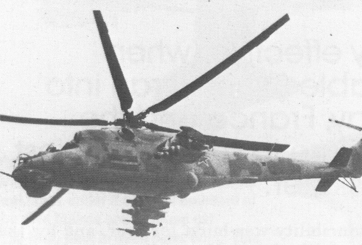
The development of the product design “240” (B-24) began immediately after the publication of the Decree of the Council of Ministers of the USSR and the Central Committee of the CPSU on May 6, 1968 at the Design Bureau of M. L. Mil, as first fire support helicopter in USSR, with accommodation for eight armed troops. Prototype machines (OP-1 and OP-2) were ready in a year. Significant part and assemblies were in common with the Mi-8 and Mi-14. Twelve prototypes were built with the first flown on 19 September 1969 (test pilot G.V. Alferov). The Mi-24 has the NATO reporting name ‘Hind’.
The prototype helicopter had a common front two-seat cockpit (the so-called “veranda”) with dual controls. Crew – pilot and operator. Later, a flight engineer was added to the crew. In the middle of the helicopter was a cargo compartment with a capacity of up to 8 personnel. On the right and left sides of the cargo compartment are double doors, with upper and lower wings. The opening windows were equipped with pivot mounts for firing during flight from personal weapons. Both cabs are sealed, supercharged by engines. Initially, the crew’s equipment included specialized flight helmets and body armor. Cabin reservation is represented by frontal bulletproof glass, armored crew seats, and local armored plates on the sides of the cabin and on the engine hoods.
Due to the unavailability of the Sturm weapons complex, it was decided on the first machines to equip the K4V complex of the Mi-4 helicopter – the Falanga-M missiles with a manual guidance system and the NUV-1 machine-gun mount with the A-12.7 machine gun, four beam holders under NUR or free-falling bombs.
Factory tests started on September 15, 1969 and almost immediately began the construction of an experimental series of ten helicopters. At the end of 1970, two machines were finished – to improve stability at speeds of more than 200 km / h, the helicopter was equipped with a wing with a negative V-12 degrees and an elongated cockpit. The first production helicopters Mi-24A (product “245”), designed in this form and equipped with the Falanga-M complex, entered the army for pilot operation.
First reported in the West in 1972, photographs became available in 1974 when two units of approximately squadron strength were based in East Germany. The Mi-24 uses the TV3 engines, transmission and rotor of the Mi-17 on a new fuselage, with stub wings carrying rockets and other offensive armament.
Two basic versions exist: the Hind A/B/C assault helicopter has a four-man crew under an extensive glasshouse canopy, while the anti-tank Hind D/E/F has a two-man crew under separate armoured glass canopies in a steel-plated forward fuselage. Both versions have stub wings to carry up to 1,500kg of stores, and eight combat equipped troops can be carried in the fuselage.
Mi-24A was produced by a factory in the city of Arsenyev. Almost 250 vehicles were built, which were put into service with the formed army aviation structures, in separate helicopter regiments of the combined arms armies and air assault brigades. On the basis of the Mi-24A, a trainer, the Mi-24U (ed. “244”) was created with full dual control.
Mi-24B (ed. ”241 ″) received a new USPU-24 machine gun mount with a YakB-12.7 machine gun (4500 h / min), the Falanga-P missile system. But the helicopter’s debugging was suspended and fundamental changes were made – the cockpit was converted into a tandem, the tail rotor and gearbox were mounted from the Mi-14 – the propeller became a pulling propeller, which sharply increased the efficiency of track control. The helicopter received the name “Mi-24V”, or product “242”. But due to the lack of knowledge of the Sturm complex, helicopters with a new cockpit had to be equipped with the Mi-24B type, and this “intermediate version” went into series under the designation Mi-24D (product “246”). Just in case, they decided not to use “G” … It took 8 years to finish the Mi-24V. In 1976, the helicopter was officially adopted and was produced in the mass series.
Thus, by 1973, the appearance of a helicopter had developed, which had become widely known throughout the world.
Mi-24 is made according to the classic single-rotor scheme with a five-blade three-joint bearing and three-blade tail rotors.
The undercarriage is three-leg, retractable, with a s steerable front wheel. In the bow of the fuselage there is a double crew cabin according to the tandem scheme: the operator-gunner is in a separate front cockpit, followed by a pilot, whose cockpit is raised by 0.3 m above the cockpit nose, the flight engineer can be located on the folding seat in the equipment compartment behind the cockpit. The crew is housed in pressurized cabins equipped with a heating and ventilation system. To prevent the entry of contaminated air and radioactive dust into them, a slight overpressure is maintained
Steel plates were used to armor the crew cabin, gearbox, engine oil tanks, gearbox and hydraulic tank. The pilot’s seat is armored, with a folding armored back and armored head, the nose is not armored, there is an armored partition between the cockpits, the windshields are armored, flat, equipped with wipers, the side convex glass is silicate, not armored.
The central section of the fuselage consists of a cargo compartment, which can accommodate up to eight paratroopers, and a rear cone-shaped part for equipment and niches for cleaning the main landing gear. The transmission and the duplicated control system are the same as on the Mi-8 helicopter.
The rotor shaft is tilted not only forward by 4.5 degrees, but also to the right by 2.5 degrees. This ensures stability during forward straight flight.
One of the main features of the helicopter is a wing with an area of 6.75 sq.m. with a negative transverse V – 12 degrees., Which provides from 22 to 28 percent of the lifting force, depending on speed and other factors.
Especially for the Mi-24 in the late 1970s, the GUV-1 helicopter gondolas (including the AGS-17 Flame automatic grenade launcher) and the GUV-8700 (one Yakb-12.7 four-barreled machine gun and two four-barrel GShG-7.62 machine guns) were created .The Mi-24 is also capable of carrying two cannon containers UPK-23-250 with a GSh-23L gun and an ammunition load of 250 shells.
At the end of the 1980s, some Mi-24Ps received 2 R-60 / R-60M air-to-air missiles to repel the attacks of enemy fighters and to combat enemy helicopters. APU with missiles mounted on internal holders. The Mi-24 is also capable of carrying two cannon containers UPK-23-250 with a GSh-23L gun and an ammunition load of 250 shells.
At the end of the 1980s, some Mi-24Ps received 2 R-60 / R-60M air-to-air missiles to repel the attacks of enemy fighters and to combat enemy helicopters. APU with missiles mounted on internal holders.
Identified by Nato is the anti-tank Hind E, armed with AT-6 Spiral missiles. A version of the Hind E without the 12.7mm Gatling-type gun in the nose, but with a twin-barrel cannon pod attached to the fuse-lage side, has been named Hind F by Nato. Hinds have also been reported carrying air-to¬-air missiles.
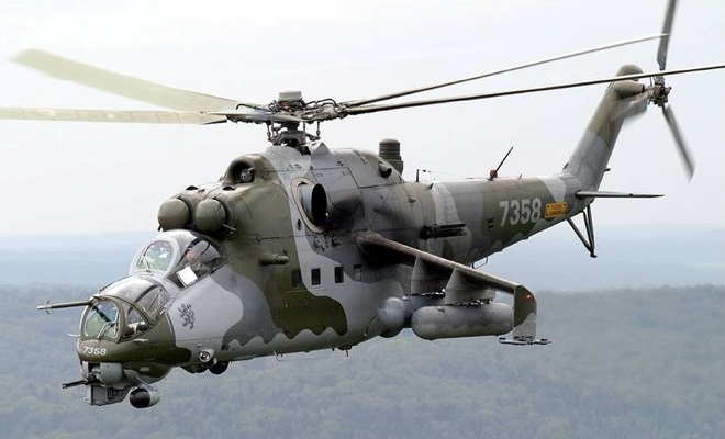
The Mi-24D has a gunship configuration, with stepped tandem seating for two crew and heavy weapon load on stub-wings, the fuselage is wide eniugh to carry eight troops. Dynamic components and power plant was originally as the Mi-8, but soon upgraded to Mi-17-type power plant and port-side tail rotor. Main rotor blade section NACA 230, thickness/chord ratio 11 to 12%; tail rotor blade section NACA 230M; stub-wing anhedral 12 degrees, incidence 19 degrees; wings contributing approximately 25% of lift in cruising flight; fin offset 3 degrees.
Five-blade constant-chord main rotor; forged and machined steel head, with conventional flapping, drag and pitch change articulation; each blade has aluminium alloy spar, skin and honeycomb core; spars nitrogen pressurised for crack detection; hydraulic lead/lag dampers; balance tab on each blade; aluminium alloy three-blade tail rotor; main rotor brake; all-metal semi-monocoque fuselage pod and boom; 5mm hardened steel integral side armour on front fuselage; all-metal shoulder wings with no movable surfaces; swept fin/tail rotor mounting; variable incidence horizontal stabiliser.
The landing gear is tricycle type; rearward-retracting steerable twin-wheel nose unit; single-wheel main units with oleo-pneumatic shock-absorbers and low-pressure tyres, size 720 x 320mm on mainwheels, 480 x 200mm on nosewheels. Main units retract rearward and inward into aft end of fuselage pod, turning through 90 degrees to stow almost vertically, discwise to longitudinal axis of fuselage, under prominent blister fairings. Tubular tripod skid assembly, with shock-strut, protects tail rotor in tail-down take-off or landing.
Power is from two Klimov TV3-117MT turboshafts, each with maximum rating of 1,434kW, side by side above cabin, with output shafts driving rearward to main rotor shaft through combining gearbox. There is 5mm hardened steel armour protection for engines. Main fuel tank in fuselage to rear of cabin, with bag tanks behind main gearbox. Internal fuel capacity 1,500kg; can be supplemented by 1,000kg auxiliary tank in cabin (Mi-24D); provision for carrying (instead of auxiliary tank) up to four external tanks, each 500 litres, on two inner pylons under each wing. Optional deflectors and separators for foreign objects and dust in air intakes; and infra-red suppression exhaust mixer boxes over exhaust ducts.
Pilot (at rear) and weapon operator on armoured seats in tandem cockpits under individual canopies; dual flying controls, with retractable pedals in front cockpit; if required, flight mechanic on jump-seat in cabin, with narrow passage between flight deck and cabin. Front canopy hinged to open sideways to starboard; footstep under starboard side of fuselage for access to pilot’s rearward-hinged door; rear seat raised to give pilot unobstructed forward view; anti-fragment shield between cockpits. Main cabin can accommodate eight persons on folding seats, or four stretchers; at front of cabin on each side is a door, divided horizontally into two sections, hinged to open upward and downward respectively, with integral step on lower portion. Optically flat bulletproof glass windscreen, with wiper, for each crew member.
Systems include cockpits and cabin heated and ventilated. Dual electrical system, with three generators, giving 36, 115 and 208V AC at 400Hz, and 27V DC. Retractable landing/taxying light under nose; navigation lights; anti-collision light above tailboom. Stability augmentation system. Electrothermal de-icing system for main and tail rotor blades. AI-9V APU mounted transversely inside fairing aft of rotor head. Blind-flying instrumentation, and ADF navigation system with DISS-1SD Doppler-fed mechanical map display. Air data sensor boom forward of top starboard corner of bulletproof windscreen at extreme nose.
Mission equipment includes undernose pods for electro-optics (starboard) and Raduga-F semi-automatic missile guidance (port). Many small antennae and blisters, including SRO-2 Khrom (NATO ‘Odd Rods’) IFF transponder.
Sirena-3M radar warning antennae on each side of front fuselage and on trailing-edge of tail rotor pylon. Infra-red jammer (L-166V-11E Jspanka microwave pulse lamp: ‘Hot Brick’) in ‘flower pot’ container above forward end of tailboom. ASO-2V flare dispensers under tailboom forward of tailskid assembly initially; later triple racks (total of 192 flares) on sides of centre-fuselage. Gun camera on port wingtip.
Armament is one remotely controlled YakB-12.7 four-barrel Gatling-type 12.7mm machine gun, with 1,470 rounds, in VSPU-24 undernose turret with field of fire 60 degrees to each side, 20 degrees up, 60 degrees down; gun slaved to KPS-53AV undernose sighting system with reflector sight in front cockpit; four 9M17P Skorpion (NATO AT-2 ‘Swatter’) anti-tank missiles on 2P32M twin rails under endplate pylons at wingtips; four underwing pylons for UB-32 rocket pods (each 32 S-5 type 57mm rockets), B-8V-20 pods each containing 20 80mm S-8 rockets, 130 mm S-13 and 250mm S-24 rockets, UPK-23-250 pods each containing a GSh-23L twin-barrel 23mm gun, GUV pods each containing either one four-barrel 12.7mm YakB-12.7 machine gun with 750 rounds and two four-barrel 7.62mm 9-A-622 machine guns with total 1,100 rounds or an AGS-17 Plamia 30mm grenade launcher, up to 1,500kg of conventional bombs, mine dispensers, night flares or other stores. R-60 (AA-8 ‘Aphid’), R-73 (AA-11 ‘Archer’) and Igla air-to-air missiles fitted experimentally. Helicopter can be landed to install reload weapons carried in cabin. PKV reflector gunsight for pilot. Provisions for firing AKMS guns from cabin windows.
Reconfiguration of the front fuselage changed the primary role to gunship. The new version was first observed in 1977. In the early Mi-24A the pilot sat behind the armament operator and had relatively poor forward vision but the later Mi-24D provided a raised rear seating position for the pilot and a bubble nose for the weapons position.
The Mi-24 was used operationally in Chad, Nicaragua, Ceylon, Angola, Afghanistan, Chechnya and Iran/Iraq war, when at least one Iranian F-4 Phantom II destroyed by AT-6 (NATO ‘Spiral’) anti-tank missile from Mi-24.
Low-rate production continued for export until 1994. Late models continued to be available from Rostvertol. By 1991 more than 2,300 had been built at Arsenyev and Rostov. An FAI record was set by the A-1O experimental variant of the ‘Hind’ on 2 September 1978 over a 15/25km course it achieved a speed of 368.4km/h.
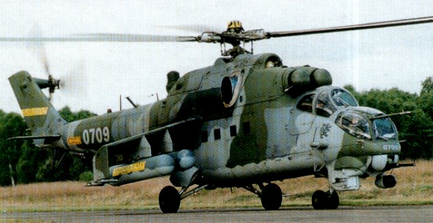
The Mi-24 has been widely exported and a number are in service on most continents, with examples delivered to, or operating in, Afghanistan, Algeria, Angola, Bulgaria, Chad, Cuba, Czechoslovakia, Germany, Hungary, India, Iraq, Libya, Mozambique, Nicaragua, North Korea, Peru, Poland, Sri Lanka, Syria, Vietnam and Yemen.
Mi-35M
Some export variants of the Mi-24 are desig¬nated Mi-25 and Mi-35, indicating a different equipment standard. The Mi-35M having fixed undercarriage.
The Mil Experimental Design Bureau demonstrated a fundamentally modernized derivative, designated the Mi-24VM (Mi-35M), of the Mi-24 helicopter that has made a perfect showing under complicated combat conditions. The features of the modernization consist in modular updating of the Mi-24. Any module (unit) can be individually modernized in accordance with the customer’s request and financial potentialities.
The Mi-25 was an export version of Mi-24D tandem-cockpit variant and Mi-35 as second and improved export variant based on upgraded versions of Mi-24.
Installation of a new main rotor provided with blades made of glass fiber plastics, a hub furnished with elastolar bearings, and an X-shaped tail rotor developed for the Mi-28N helicopter, makes it possible to decrease the mass of the flying machine, increase its hovering ceiling and rate of climb, and improve its overall operating characteristics and invulnerability.
In modernizing the airframe, armament system and communications facilities, the Mil Design Bureau offers to install a shortened wing and nonretractable landing gear and retrofit the hydraulic system. The primary emphasis has been placed on an increase of weapon effectiveness. The Ataka air-to-ground guided missiles (ammunition establishment has been increased up to 16 missiles) have been introduced into the helicopter’s armament system. The missiles can also be used against air targets similar to the Igla-V guided missiles. The 12.7mm machine-gun mount has been replaced by a 23mm aircraft cannon. The most up-to-date BVK-24 computer and a laser range finder have been introduced into the heliborne equipment. A modernization program on this scale makes it possible to increase the accuracy against a single target 1.5 times, while increasing the kill zone 2 to 2.5 times when delivering cannon fire. The combat effectiveness of employing the guided missiles increases twofold on average.
The use of night-vision goggles with flight information displayed in the field of view, and equipping the helicopter with an optronic fire-control station comprising of thermal imaging and TV channels, control channel, and laser range finder, as well as display systems, enables the crew to detect and recognize targets at night and employ the heliborne weapons both by day and night.
Most of over 2,500 built between 1970 and 1989, though smallscale production up to 1996.
Mi-24 ‘Hind’ Early production version, reported in 1972 but not seen until 1973; introduced into Soviet service in 1973/74
Mi-24 ‘Hind-A’ Second production model, with tail rotor moved from the starboard to port side of the tailfin; used as armed assault helicopter, carrying eight troops and three crew members
Mi-24 ‘Hind-B’ Initial production model with tail rotor on starboard side, wings without anhedral, no wingtip stations and only four underwing hardpoints; test use only
Mi-24 ‘Hind-C’ Dedicated training helicopter similar to ‘Hind-A’, but without nose-gun installation and wingtip stations
Mi-24BMT Modified 1973 for minesweeping.
Mi-24D: (Type 24-6; ‘Hind-D’) Interim gunship version; design began 1971; entered production at Arsenyev and Rostov plants 1973; about 350 built 1973-77. Basically as late model ‘Hind-A’ with TV3-117 engines and port-side tail rotor, but entire front fuselage redesigned above floor forward of engine air intakes; heavily armoured separate cockpits for weapon operator and pilot in tandem; flight mechanic optional, in main cabin; transport capability retained; USUP-24 gun system, with rangefinding; undernose JakB-12.7 four-barrel 12.7mm machine gun in turret, slaved to adjacent KPS-53A electro-optical sighting pod, for air-to-air and air-to-surface use; Falanga P (Phalanx) anti-tank missile system; nosewheel leg extended to increase ground clearance of sensor pods; nosewheels semi-exposed when retracted.
Mi-24DU Dual-control training version has no gun turret.
Mi-24K (korrektirovchik: corrector) (‘Hind-G2’) As Mi-24R, but with large camera in cabin, f8/1,300mm lens on starboard side; six per helicopter regiment for reconnaissance and artillery fire correction; gun and B-8V-20 rocket pods retained. No target designator pod under nose; upward hingeing cover for IR sensor. About 150 built 1983-89.
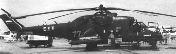
Mi-24P (Type 24-3; ‘Hind-F’) Development started 1974; about 620 built 1981-90; first shown in service in 1982 photographs; P of designation refers to pushka = cannon; as Mi-24V, but nose gun turret replaced by GSh-30-2 twin-barrel 30mm gun (with 750 rounds) in semi-cylindrical pack on starboard side of nose; bottom of nose smoothly faired above and forward of sensors.
Mi-24PS Special version for Russian Ministry of Internal Affairs; prototype exhibited at Moscow Air Show ’95. Equipment includes undernose FLIR, searchlight on port side, loadspeaker pack on starboard side; hoist, climbdown ropes, stations for radio operator.
Mi-24R ‘Hind-G 1’ Fitted with wingtip ‘grapplers’ or ‘clutching hands’ apparently used in connection with NBC technology, the Mi-24R was first reported in 1986 after the Chernobyl disaster
Mi-24RKR (‘Hind-G1’) Identified at Chernobyl after April 1986 accident at nuclear power station; no undernose electro-optical or RF missile guidance pods; instead of wingtip weapon mounts, has ‘clutching hand’ mechanisms on lengthened pylons, to obtain six soil samples per sortie for NBC (nuclear/biological/chemical) warfare analysis; air samples sucked in via pipe on port side, aft of doors; datalink to pass findings to ground; lozenge-shaped housing with exhaust pipe of air filtering system under port side of cabin; bubble window on starboard side of main cabin; small rearward-firing marker flare pack on tailskid; crew of four wear NBC suits; six helicopters are deployed per regiment throughout RFAS ground forces. Designation (also appearing as Mi-24RCh) indicates Razvedchik: reconnaissance/chemical. About 150 built 1983-89.
Mi-24RR Derivative of Mi-24R for radiation reconnaissance.
Mi-24V (Types 20-1 and 24-2; ‘Hind-E’) As Mi-24D, but modified wingtip launchers and four underwing pylons; weapons include up to eight 9M114 (NATO AT-6 ‘Spiral’) radio-guided tube-launched anti-tank missiles in pairs in Shturm V (Attack) missile system; ASP-17V enlarged undernose automatic missile guidance pod on port side, with fixed searchlight to rear; R-60 (K-60; NATO AA-8 ‘Aphid’) air-to-air missiles optional on underwing pylons; pilot’s HUD replaces former reflector gunsight. Deliveries to former Soviet Air Force began 29 March 1976; about 1,000 built at Arsenyev and Rostov 1976-86.
Mi-24VM Proposed upgrade first shown in model form at Moscow Air Show ’95.
Mi-24VP Variant of Mi-24V with twin-barrel 23mm GSh-23 gun, with 450 rounds, in place of four-barrel 12.7mm gun in nose; photographed 1992; small production series built at Rostov.
Mi-24W ‘Hind-E’ Improved version of ‘Hind-D’ gunship first reported in early 1980s; equipped with 12 AT-6 ‘Spiral’ radio-guided ATMs mounted on stub wings together with AA-8 ‘Aphid’ air-to-air missiles for self-defence
Mi-24 Ecological Survey Version Modification by Polyot industrial research organisation, to assess oil pollution on water and seasonal changes of water level. First seen 1991 with large flat sensor ‘tongue’ projecting from nose in place of gun turret; large rectangular sensor pod on outer starboard underwing pylon; unidentified modification replaces rear cabin window on starboard side.
Mi-25 Export Mi-24D ‘Hind-D’, including those for Afghanistan, Cuba and India with inferior electronics.
Mi-35 Export Mi-24V ‘Hind-E’. Unarmed, dual-control trainer version also produced for India.
Mi-35M Upgraded Mi-24/35 designed to meet the latest air mobility requirements of the Russian Army.
Mi-35M1 Upgrade of production standard of Mi-24VP.
Mi-35P Export Mi-24P ‘Hind-F’.
ATE ‘Super Hind’ Upgrade configuration proposed by South Africa’s Advanced Technologies and Engineering. Derived from Denel/Kentron PZL W-3WB Huzar upgrade. Extended nose in front of cockpit with undernose Kentron IR/EO sight and 20mm chain gun, cheek fairing to port for ammunition feed, designator, improved displays, new night vision systems and provision for Denel/Kentron Ingwe or Mokopa ATMs. Prototype ZU-BOI rolled out at Grand Central Airport, Midrand, by 15 February 1999.
Tamam Mi-24 HMOSP Israeli upgrade configuration. US$20 million contract placed for upgrade of 25 (possibly Indian) Mi-24s based on existing Helicopter Multimission Optronic Stabilised Payload System, with TV, FLIR and automatic target tracker, integrated with helmet sight, digital moving map, integrated DASS and a new mission planning system. Cockpits can be reorganised to put pilot in front, weapon operator in rear.
Specifications:
Mi-24 Engine: 2 x Klimov TV3-117 Instant pwr: 1633 kW Main rotor diameter: 18.8m Height: 4.17m Empty weight: 7580kg Normal take-off weight: 10,500 kg MTOW: 11,500 kg Payload: 2400 kg Max external load: 2400 kg Internal fuel: 2100 kg Average fuel consumption: 780 l / h Max speed: 180 kts / 335km/h Max cruise: 100 kts Cruise speed: 217-270km/h HOGE: 4920 ft / 1500m Rate of climb: 12.5m/s Range: 1000km Service ceiling: 14,750 ft / 5000m Permissible roll angle: 50 degrees. Allowed pitch angle: 30 degrees. Crew: 2-3 Pax: 8
Hind-A Engines: 2 x 2200 hp / 1640 kW TV3-117 Gross weight: 22,000 lb / 9500 kg approx Max speed: 180 mph / 276 mph Armament: usually one 12.7 mm gun aimed from nose; two stub wings providing rails for four wire-guided anti-tank missiles and four other stores (bombs, missiles, rocket or gun pods). (Hind-B) two stub wings of different type with four weapon pylons.
Mi-24 Hind D Engine: 2 x Isotov TV3, 2,200-shp Installed pwr: 3280 kW Rotor dia: 17 m Fuselage length: 17.5 m Length rotors turning: 21.5 m Disc area: 226.98 sq.m Height: 6.5m No. Blades: 5 Empty wt: 8400 kg MTOW: 12,500 kg Payload: 1500 kg Max speed: 310 kph ROC: 750 m/min Service ceiling: 4500 m HOGE: 2200 m Range: 750 km Crew: 2 Pax: 8 Armament: one 12.7-mm (0.5-in) multi-barrel machine gun and up to 5,732 lb (2,600 kg) of disposable stores.
Mi-24P Primary Function: Armed assault/attack helicopter Engines: Two Klimov TV3-117 turboshafts, 1635 kW Main rotor: five blade Tail rotor: 3-blade Length: 57 ft 5 in (17.51 m) Rotor Diameter: 56 ft 9 in (17.30 m) Height: 13 ft 1 in (3.97 m) Empty: 18,078 lb (8200 kg) Maximum Takeoff: 26,455 lb (12,000 kg) Speed: 335 km/h Ceiling: 14,750 ft Range with aux. fuel: 1000 km Crew: Two Cabin: 8 troops or 14 stretchers
Mi-24VM Crew: 2-3 Rotor diameter: 17.20m Fuselage length with a gun: 18.57m Height: 4.39m Max take-off weight: 10800-11500kg Empty weight: 8090kg Max speed: 310km/h Cruising speed: 260km/h Service ceiling: 5700m Hovering ceiling: 3100m Range: 500km Fuel: 2050 lt Armament: 23mm cannon, 4 x “Ataka” anti-tank missiles, 2 x “Igla” anti-aircraft missiles, 40 x 80mm rockets
Mil Mi 24 W Engines: 2 x TW3-117WM, 2195 shp Length: 57.448 ft / 17.51 m Height: 17.946 ft / 5.47 m Rotor diameter: 56.759 ft / 17.3 m Max take off weight: 25357.5 lb / 11500.0 kg Max. speed: 181 kts / 335 km/h Service ceiling: 15092 ft / 4600 m Range: 607 nm / 1125 km Crew: 2 Armament: 1x MG 12,7mm JakB-12,7, 1200kg ext.
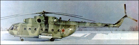
First identified in 1980-81, the Mi-17 is virtually a revision of the Mi-8 design using a combination of the ‘Hip’ airframe but with the port-side tail rotor, and fitted with the more powerful powerplants of the Mi-14. A new rotor hub of titanium alloy was developed for the Mi-17. These result in an overall improvement in performance, particularly the hovering ceiling. The Mi-17 retains the codename ‘Hip-H’.
Distinguished from basic Mi-8 by port-side tail rotor; shorter engine nacelles, with air intakes extending forward only to mid-point of door on port side at front of cabin; small orifice each side forward of jetpipe; correct rotor speed maintained automatically by system that also synchronises output of the two engines. For operation in ‘hot and high’ conditions, Kazan commercial versions can be supplied with TV3-117MT engines and tail rotor with wider-chord blades.
Mil Mi-17
The basic Mi-17 is powered by two 1,434kW (1,923 shp) Klimov TV3-117MT turboshafts. Should one engine stop, output of the other increases automatically to contingency rating of 1,637kW (2,195 shp), enabling flight to continue. An APU for pneumatic engine starting is provided,and deflectors on engine air intakes prevent ingestion of sand, dust and foreign objects. Single flexible internal fuel tank, capacity 445 litres; two external tanks, each side of cabin, capacity 745 litres in port tank, 680 litres in starboard tank; total standard fuel capacity 1,870 litres. Provision for one or two ferry tanks in cabin, raising maximum total capacity to 3,700 litres. Configuration and payloads generally as Mi-8 but six additional centreline seats optional. Military Mi-17-1V carries up to 30 troops or 20 wounded troops in ambulance configuration. Civilian Mi-17 promoted as essentially a cargo-carrying helicopter, with secondary passenger transport role.
Mi-17V/171 systems include AI-9V APU for pneumatic engine starting, and AC electrical supply from two 40kW three-phase 115/220V 400Hz GT40/P-48V generators. Avionics include Baklan-20 and Yadro-1G1 com radio and Type 8A-813 weather radar. Optional are ASO-2 chaff/flare dispenser under tailboom and IR jammer (NATO ‘Hot Brick’) at forward end of tailboom.
Equipment and armament options are as for the Mi-8, plus, on military versions, external cockpit armour; engine nozzle IR suppressors and a VMR-2 fit for air-dropping, 23mm GSh-23 gun packs, AAMs and newer ASMs on Mi-8AMTSh.
Revealed to the world at the 1981 Paris air show, the Mi-17 is known by the Russian military as the Mi-8M. Export customers and Russian civilian operators use the Mi-17 designation.
Entered service with Soviet forces in 1977 as Mi-8MT. The first export examples were delivered to Cuba in 1983, and Mi-17s were in service in Angola, Hungary, India, North Korea, Nicaragua, Papua New Guinea, Peru and Poland, as well as the CIS.
Mi-171
Mi-8 derivatives include Mi-17 (first flown August 1975) with change of engines and other modifications and Mi-171/Mi-172 export models, and lengthened Mi-173. Individual factories continue to develop new Mi-17 variants, like the Mi-171 produced by the Ulan Ude factory. Production of Mi-17M/V and Mi-172 for both civil and military use as a cargo-carrying helicopter, with secondary capability as a passenger transport capable of carrying up to 24 passengers, or 12 stretcher cases when used as an ambulace was at Kazan and Mi-171 at Ulan-Ude plants, from where they are marketed. More than 810 exported by Aviaexport. Production of both the Mi-8 and Mi-17 continued in 1987.
Long-range modification: AEFT (Auxiliary External Fuel Tanks) system by Aeroton adds a further 1,900 litres in two internal tanks, plus 2,850 litres in six tanks on the stores pylons of Mi-8MT, -AMT, -MTV-1, civil MTV and Mi-17 variants. Operational range with all eight auxiliary tanks is 1,300km; ferry range 1,850km.
Versions:
Mi-17 (‘Hip-H’) Mid-life update of Mi-8 with more powerful turboshafts, giving overall performance improvement, particularly hover ceiling. All versions in RFAS military service retain Mi-8 designation.
Mi-17KF Derivative of Mi-17 jointly developed by Kazan and Mil, with systems integration provided by Kelowna Flightcraft (Canada). First flown 3 August 1997. Certified to FAR Pt 29 for full IFR operation.
Mi-17MD Prototype converted from Mi-8MTV (RA70937); displayed at 1995 Paris Air Show; with rear loading via a short ramp and two clamshell doors; further modified with large single-piece rear loading ramp and other changes. Given dual designation Mi-17MD/Mi-8MTV-5 when equipped with IR jammer and flight deck armour. Also known as Mi-17N (Noch: Night). First delivered to South Korean Police.
Mi-17P (Mi-8 MTPB) (‘Hip-K derivative’) ECM communications jammer; two observed in Hungarian service in 1990; antenna array much more advanced than that of Mi-8 (‘Hip-K’); large 32-element array, resembling vertically segmented panel, aft of main landing gear each side; four-element array to rear on tailboom each side; large radome each side of cabin, below jet nozzle; triangular container in place of rear cabin window each side; six heat exchangers under front fuselage.
Mi-17PI As Mi-17P but single D-band jamming system able to jam up to eight sources simultaneously over 30degree sector.
Mi-17PG As Mi-17P but with H/I-band system for jamming pulse/CW and CW interrupted equipment.
Mi-17-1V Export version of Mi-8MTV (‘Hip-H’) (Visotnyi: high altitude); TV3-117VM turboshafts for improved ‘hot and high’ performance, built by Kazan Helicopter Plant; optional armament, nose radar, flotation gear and firefighting equipment. Civil version designated Mi-8MTV-1, military Mi-8MTV-2; civil export version Mi-8MTV-GA (Grazhdanska Aviatsia).
Mi-17-5V Kazan-built production model with port side door enlarged from 0.83m to 1.25m; new 0.83m wide starboard sliding door; rear flat ramp with single hydraulic cylinder drive installed on helicopter floor and capable of being lowered to horizontal position in flight, permitting disembarkment of up to 36 troops in 15 seconds. Series production started in 1999. Military equivalent designated Mi-8MTV-5.
Mi-171 (‘Hip-H’) First displayed 1989 Paris Air Show; more powerful TV3-117VM turboshafts, each 1,545kW; improved rates of climb and hover ceilings; other weights and performance generally unchanged. Export version of Mi-8AMT.
Mi-171AG Proposed long-range version with TV3-117SB3 turboshaft engines and improved main rotor blades; range up to 1,500km.
Mi-171Sh Export version of Mi-8AMT built at Ulan-Ude.
Mi-17-1VA Version produced for Ministry of Health of former Soviet Union as flying hospital equipped to highest practicable standards for relatively small helicopter; interior, with equipment developed in Hungary, had provision for three stretchers, operating table, extensive surgical and medical equipment, accommodation for doctor/surgeon and three nursing attendants.
Mi-171
Mi-172 (Mi-8MTV-3) As Mi-17M/17V, also from Kazan, but with equipment changes and planned for certification to FAR Pt 29 standards; TV3-117VM Srs 2 engines, giving maximum cruising speed of 218km/h and service ceiling of 6,000m; air conditioning and heating systems, main and tail rotor blade de-icing, canopy demisting and heating of engine air intakes standard; options include flotation gear, Doppler, weather radar, DME, GPS, VOR, ILS, transponder and VIP interiors for seven, nine and 11 passengers. Standard seating for up to 26 passengers. First exhibited at 1994 Singapore Air Show. Seven ordered by Mesco, India, Spring 1995.
Mi-172-II Converted from ‘Hip-H’ in former Czechoslovakia for electronic warfare role; first seen in Czech Air Force service at Dobrany-Line airbase, near Plzen, 1991; each of two examples had a tandem pair of large cylindrical containers mounted each side of cabin; assumed that containers made of dielectric material and contain receivers to locate and analyse hostile electronic emissions; each of two operators’ stations in main cabin has large screens, computer-type keyboards and oscilloscope; several blade antennae project from tailboom.
Mi-19 Generally similar to Mi-9; command relay platform variant of Mi-8MT (Mi-17).
Mi-8AMTSh Counterpart of Mi-8MTV series built at Ulan-Ude; combat and troop-carrying version with thimble radome on nose and chin-mounted electro-optics pod. Armament includes Igla-V AAM or Shturm-V ASM missile systems, B8V20 rocket pods and GSh-23 gun.
Mi-8AMT Designation for unarmed version of Mi-8MT used by RFAS, but also applied to some civil (perhaps ex-military) examples.
Mi-8MT (‘Hip-H’) Designation of standard Mi-17s in RFAS military service. Twin or triple stores racks, but normal armament is 40 x 80mm S-8 rockets in two BV-8-20A packs. Afghan experience led to adoption of nose armour, IR jammer, IR suppressors and provision for door-mounted PKT machine gun (rear starboard) and AGS-17 Plamya grenade launcher or NSV 12.7mm Utyos heavy machine gun (forward port cabin door).
Mi-8MT EW More than 30 EW versions of the Mi-8MT serve with RFAS armed forces, under the designations Mi-8MTSh, Mi-8MTPSh, Mi-8MTU, Mi-8MTA, Mi-8MTP, Mi-8MTPB, Mi-8MTR, Mi-8MTI, Mi-8MTPI and Mi-8MTTs.
Mi-8MTPB (or Mi-17P, Mi-17PP) (‘Hip-H EW’) ECM (radar and communications jammer) and comint helicopter, with three jamming systems in D/F band range over 30 degree sector and other frequencies over 120 degrees. Operating time 4 hours. Antenna array more advanced than that of Mi-8PPA (‘Hip-K’); large 32-element array, resembling vertically segmented panel, aft of main landing gear each side; four-element array to rear on tailboom each side; large radome each side of cabin, below jet nozzle; triangular container in place of rear cabin window each side; six heat exchangers under front fuselage. (Mi-17P designation used also for civil export versions.) Similar versions include Mi-8MTI (Mi-17 with small horizontal array on forward part of boom and larger box-like radome on cabin side); Mi-8MTTs2 and Mi-8MTTs3 with non-rectangular (‘teardrop’) radome on cabin sides and less regularly shaped arrays on sides of rear cabin.
Mi-8MTV (‘Hip-H’) (V=visotnyi: high altitude); TV3-117VM turboshaft for improved ‘hot and high’ operation. Civil version built at Kazan is Mi-8MTV-1; Russian presidential aircraft with new Abvis navigation system is designated Mi-8MTV-1S; missile-armed, radar-equipped military version with six-hardpoint stub-wing is Mi-8MTV-2; export equivalent is Mi-17-1V, with optional armament, nose radar, flotation gear and firefighting equipment. Mi-8MTV-5 is military version with one-piece rear loading ramp: Ulan-Ude equivalent to Kazan Mi-17MD.
Mi-17 Engines: two Isotov TV3-117MT turboshafts, 1400kW / 1,900 shp (with 2,200 shp emergency) Normal take-off weight: 24,470 lb (11100 kg) Max take-off weight: 28,660 lb (13 000 kg) Max useful load: 8,818 lb (4 000 kg) Max speed: 155 mph (250 km/h) Max cruise: 149 mph (240 km/h) Service ceiling: 16,405 ft (5 000 m) Service ceiling max weight 11,810 ft (3600 m) Cabin: 812 cu ft (23 cu.m) Passengers: 24 Main rotor diam: 69.86 ft (21.294 m) Overall length: 83.18 ft (25.352 m) Fuselage length: 60.45 ft (18.424 m) Height: 4.76m Hovering ceiling, OGE: 1760m Range: 465km Payload: 3000-5000kg
Mi-17 Hip-H Engine: 2 x Klimov TV3-117MT Instant pwr: 1434 kW Rotor dia: 21.6 m MTOW: 13,000 kg Payload: 4000 kg Max speed: 135 kts Max cruise: 130 kts Max range: 495 km HOGE: 5575 ft Service ceiling: 16,400 ft Crew: 2 Pax: 32 Rotor dia: 69 ft 10 in / 21.6 m Length overall: 82 ft 10 in Fuselage length: 59 ft 8 in Height: 18 ft 7 in Disc area: 3932 sq.ft
Mil Mi 17 T Engines: 2 x TW 3-117MT, 1874 shp Length: 59.744 ft / 18.21 m Height: 18.537 ft / 5.65 m Rotor diameter: 69.849 ft / 21.29 m Max take off weight: 28665.0 lb / 13000.0 kg Weight empty: 15655.5 lb / 7100.0 kg Max. speed: 135 kts / 250 km/h Cruising speed: 119 kts / 220 km/h Service ceiling: 16404 ft / 5000 m Range: 594 nm / 1100 km Fuel capacity: 494 gal / 1870 lt Crew: 3 Payload: 28-32 pax
Mi-171 Engines: 2 x 1545 kW (2070 shp) Klimov (Isotov) TV3-117M turboshaft Max speed: 135 kts Max cruise speed: 124 kts Service ceiling: 18,700 ft Range with res: 307nm Range with 2 ext. tanks: 575 nm Empty equipped Wt: 15,555 lbs MTOW: 28,660 lbs Rotor dia: 69 ft 10 in Length overall: 83 ft 2 in Fuselage length: 60 ft 6 in Height: 18 ft 7 in Disc area: 3932 sq.ft