Japan’s interest in jets increased in September 1944, when the Japanese air Attache in Berlin sent a large number of detailed reports on the German Me262 program. The Japanese naval staff instructed Nakajima to develop a single seat attack bomber based on the Me 262, capable of a speed of 690 km/h (430 mph) and able to carry a small bombload.
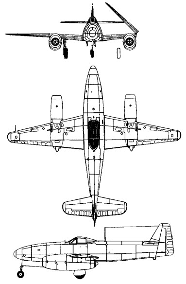
Design started in Septem¬ber 1944 under the direction of Kazuo Ohno and Kenichi Matsumur, and the resulting aircraft resembled the Ger¬man design although somewhat smal¬ler owing to the very low power avail¬able from the early Japanese jet en¬gines. The Kikka first design studies envisaged the use of 440 lb. thrust TSU-11 units which were based on the Campini principles and employed the Hitachi Hatsukaze (Fresh wind) piston engine to drive a ducted fan compressor. However, at an early design stage the Tsu-11 was dropped in favour of the Ne-10 (TR-10) centrifugal-flow turbojet, and the 340 kg (750¬lb) thrust NE-12 (TR-12), which added a four-stage axial compressor to the front of the Ne-10. The first mock-up of the Kikka was inspected by Naval Officials on January 28, 1945, but estimated performance with the NE-12 turbo jet was uninspiring, and it was decided to make a further power plant change, supplanting the NE-12 with two 475 kg (1,047 1b) thrust powerful NE-20.
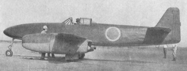
The Kikke was a single-seat twin-jet attack bomber, of all-metal construction with fabric-covered tail surfaces.
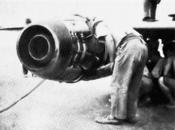
Ishikawajima NE-20 fitted on Kikka No1
These also proved inadequate and for the first flight Ne 20 axial flow turbojets were fitted; however, it was still necessary to employ an auxiliary rocket for assisted take off.
The prototype commenced ground tests at the Nakajima factory on 20th may 1945, and on 25th June the first Kikka was completed. The following month it was dismantled and delivered to Kisarazu Naval Air base where it was re-assembled and prepared for flight testing. Ground tests continued on this airfield until 13th July.
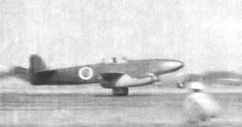
On the 7th August 1945, Lieutenant Commander Susumu Takaoka made the first flight, with a duration of 11 minutes at Kisarazu Naval Air Base. His take-off run of 2,380 ft. took 25 seconds at an all-up weight of 6,945 lb. Wind speed was 23 ft.per second. He landed in 3,280 ft.
A ceremonial official “initial” test flight was made on 11th August, four days later. For this flight, rocket assisted take off (RATO) units were fitted to the aircraft. Because their alignment had been miscalculated, the acceleration was so heavy that the nose of the aircraft came up, the tail went down and skidded along the runway. Tanaoka abandoned the take off and the aircraft was damaged when it ran off the end of the runway. Before it could be repaired Japan had surrendered and the war was over.
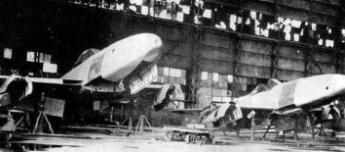
A second prototype was then nearing completion and manufacture of between 18 and 25 further aircraft had started. Some of these were two-seat trainers. On 15 August, the entire programme was abandoned. Production, which included versions for training, reconnaissance and air combat, had also been planned.
Kikka (1st prototype) Powerplant: two Ishikawajima Ne 20 axial flow turbojets, 475 kg (1,047 1b) thrust Wing span 10.00 m (32 ft 10 in) Length 8.125 m (26 ft 8 in) Height 2.95 m (9 ft 8 in) Wing area 13.2 sq.m (142.08 sq.ft) Empty weight 2300 kg (5,071 lb) Maximum take off weight 4080 kg (8,995 lb) Wing loading: 54.3 lb./sq. ft. Power loading: 3.7 lb./lb. s. t. Max speed sea level (est): 387mph Max speed 697 km/h (433 mph) at 10000 m (32,810 ft) Climb to 10000 m (32,810 ft) in 26 min Service ceiling 12000 m (39,370 ft) Range 940 km (586 miles) Armament: one 800 kg (1,764 lb) bomb Crew: 1
The 1963 VG-1 Vertigyro (N5395Z) comprised a Piper Colt aircraft fuselage, complete with engine and prop. Its Sud Djinn rotor system was driven by a turbine engine, enabling the craft to be flown as a gyroplane, a helicopter, or a combination of both. Only the one was built.
The vehicle could take off and fly as a helicopter at 75mph, powered by a Garret-AiResearch GTC-85-90 gas turbine to feed compressed air to nozzles in the two-blade rotor, then convert into an autogyro to do 85mph powered by the one 108hp Lycoming O-235.
Engines: 1 x Garret-AiResearch GTC-85-90 gas turbine / 1 x Lycoming O-235, 108hp Rotor diameter: 36 ft 0 in Minimum gyro speed: 45 mph Seats: 2
One other version of the M-4 ‘Bison’ is known, a test-bed aircraft powered by four D-15 turbojet engines each of 13000kg thrust and designated 201-M.
This was used in September 1959 to establish a number of payload-to-height records by lifting a payload of 10,000 kg (22,046 lb) to 50,253 ft (15,317 m) and the weight of 55,220 kg (121,480 lb) to 2000 m (6,561 ft).
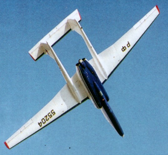
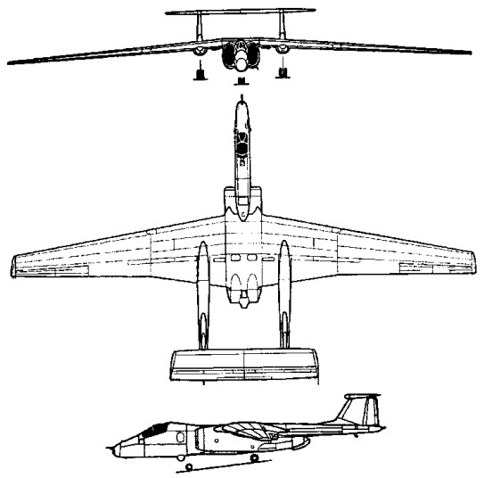
Originally identified in 1982 by US reconnaissance satellites as the ‘Ram-M’ single-seat high-altitude reconnaissance aircraft, and later codenamed ‘Mystic’ by NATO, the twin-boom straight-wing jet, was publicised as a high-altitude research aircraft able to carry around 1500kg of sensors, existing in two versions.
The first of two prototype aircraft, designated M-17 Stratosfera (‘Mystic-A’), first flew in 1988 and are powered by a single 68.6kN thrust Rybinsk RD-36-51V turbojet developed from the Tu-144 SST powerplant.
The M-55 Geofizika (‘Mystic-B’), has two 49kN thrust Perm/Soloviev PS-30-V12 turbojets mounted side-by-side behind a raised cockpit installed in a longer nose, together with a reduced span wing. The M-55 ‘Mystic-B’ differs from the first M-17 Stratosfera in having a longer jetpipe, shorter engine intakes, a reprofiled nose and an undernose FLIR turret.
The role of the ‘Mystic-B’ is described as environmental sampling missions or high-altitude research and endurance in this role is claimed as over 4 hours loiter capability at 20000m. A further variant of the M-55 is reported to be under development with wingroot mounted engines in stalled in a conventional fuselage carrying a sweptback tail unit.
Two ‘Mystic-A’ prototypes were followed by two ‘Mystic-B’ and two pre-production ‘Mystic-Bs’ were flying by 1992.
Engines: 2 x Soloviev PS-30-V12, 49kN Wingspan: 37.47 m / 122 ft 11 in Length: 22.87 m / 75 ft 0 in Height: 4.83 m / 15 ft 10 in Cruise speed: 750 km/h / 466 mph Ceiling: 21000 m / 68900 ft Crew: 1
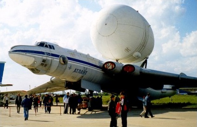
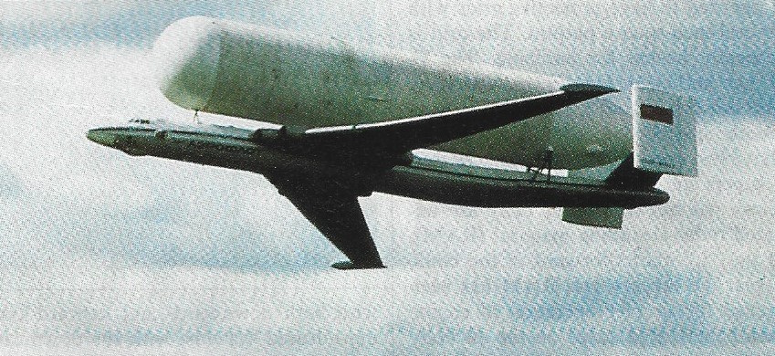
After directing CAHI (TsAGI) from 1960, Myasishchev returned to OKB No 23 in early 1978 in order to study how a 3M strategic bomber might be modified to convey large space launchers and similar payloads. In particular an aircraft was needed to transport to the Baikonur launch site four kinds of load: the nose of the Energiya launcher; the second portion of Energiya; the Energiya tank; and the Buran spacecraft, with vertical tail and engines removed. These loads typically weighed 40 tonnes and had a diameter of 8m. Myasishchev had previously calculated that such loads could be flown mounted above a modified 3M bomber. He died on 14th October 1978, the programme being continued by V Fedotov. While design went ahead, three 3M tanker aircraft were taken to SibNIA (the Siberian State Research Instiutute named for S.A.Chaplygin) and put through a detailed structural audit preparatory to grafting on a new rear fuselage and tail, and mountings for the external payload. The modified aircraft were designated 3M-T. All were rebuilt with zero-life airframes and new engines, but initially without payload attachments. One was static-tested at CAHI while the other two were completed and flown, tne first on 29th April 1981. After a brief flight-test programme they were equipped to carry pick-a-back payloads, and in Myasishchev’s honour redesignated VM-T Atlant. The first flight with a payload was made by A.Kucherenko and crew on 6th January 1982. Subsequently the two Atlant aircraft carried more than 150 payloads to Baikonur.
The most obvious modification of these aircraft was that the rear fuselage was replaced by a new structure 7m longer and with an upward tilt, carrying a completely new tail. This comprised modified tailplanes and elevators with pronounced dihedral carrying inward- sloping fins and rudders of almost perfectly rectangular shape, with increased total area and outside the turbulent wake from any of the envisaged payloads. Less obvious was the fact that, even though the maximum take-off weight was less than that for the bomber versions, the airframe was strengthened throughout.
As time between overhauls was not of great importance the original four VD-7B engines were replaced by the VD-7M. These were RD-7M-2 engines, originally built for the Tu-22 supersonic bomber with afterburners and variable nozzles, which had had the afterburner replaced by a plain jetpipe and fixed-area nozzle. Thrust was 11,000kg. These were in turn replaced by the VD-7D, rated at 10,750kg. Each aircraft was fitted with 14 attachment points above the fuselage and on lateral rear-fuselage blisters for the four different kinds of supporting structure, each being specially tailored to its payload. They were also equipped with a modified flight-control and autopilot system. The forward fuselage was furnished with work stations for a crew of six.
The aircraft were given civilian paint schemes, one being registered RF-01502 and the other being RF-01402 and fitted with a flight-refuelling probe. To support their missions the PKU-50 loading and unloading facility was constructed at spacecraft factories, including NPO Energiya at Moscow Khimki, and at the Baikonur Cosmodrome. These incorporated a giant gantry for carefully placing the payloads on the carrier aircraft. Despite the turbulent aerodynamics downstream of the external payloads, this dramatic reconstruction proved completely successful.
Max take-off weight: 136400 kg / 300712 lb Max. speed: 600 km/h / 373 mph Cruise speed: 540 km/h / 336 mph Ceiling: 9500 m / 31150 ft Range w/max.fuel: 3000 km / 1864 miles Range w/max.payload: 1500 km / 932 miles Crew: 6
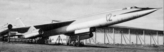
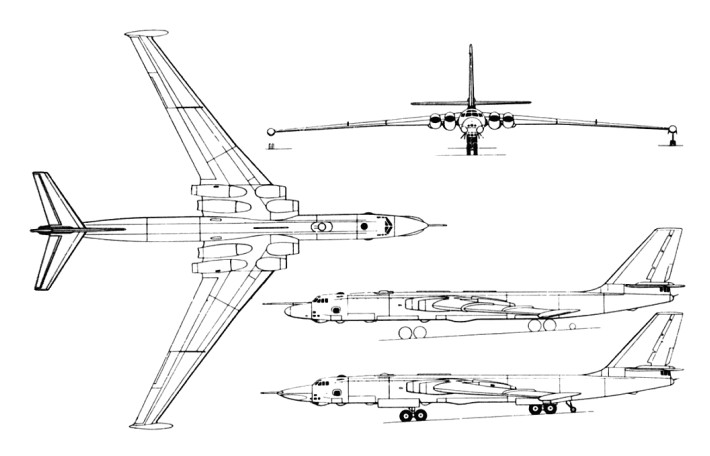
To succeed its M-4, Myasishchyev produced the M-50, codenamed ‘Bounder’ by NATO.
It was based on a very long area-ruled fuselage with two four-wheel main landing gear bogies arranged in tandem to retract into the lower fuselage. This was basically the same arrangement as that used in the M-4, as was the use of two twin-wheel stabilizers of the outrigger type that retracted aft into the wingtips. The cropped delta wing was located in the shoulder position with its leading edges swept at 500 inboard decreasing to 41030’ outboard. The tail unit was conventional for a supersonic type, with powered all-moving slab tailplane halves and a fin with a powered rudder.
The crew of three was accommodated in a pressurized nose compartment on tandem ejector seats behind a V-shaped windscreen whose contours were continued aft of the cockpit by a long dorsal spine stretching as far as the extreme tail. In the first aeroplane the four engines were located on pylons under the wing leading edges. Power was provided by four Soloviev D-15 turbo-jets of 13000kg thrust.
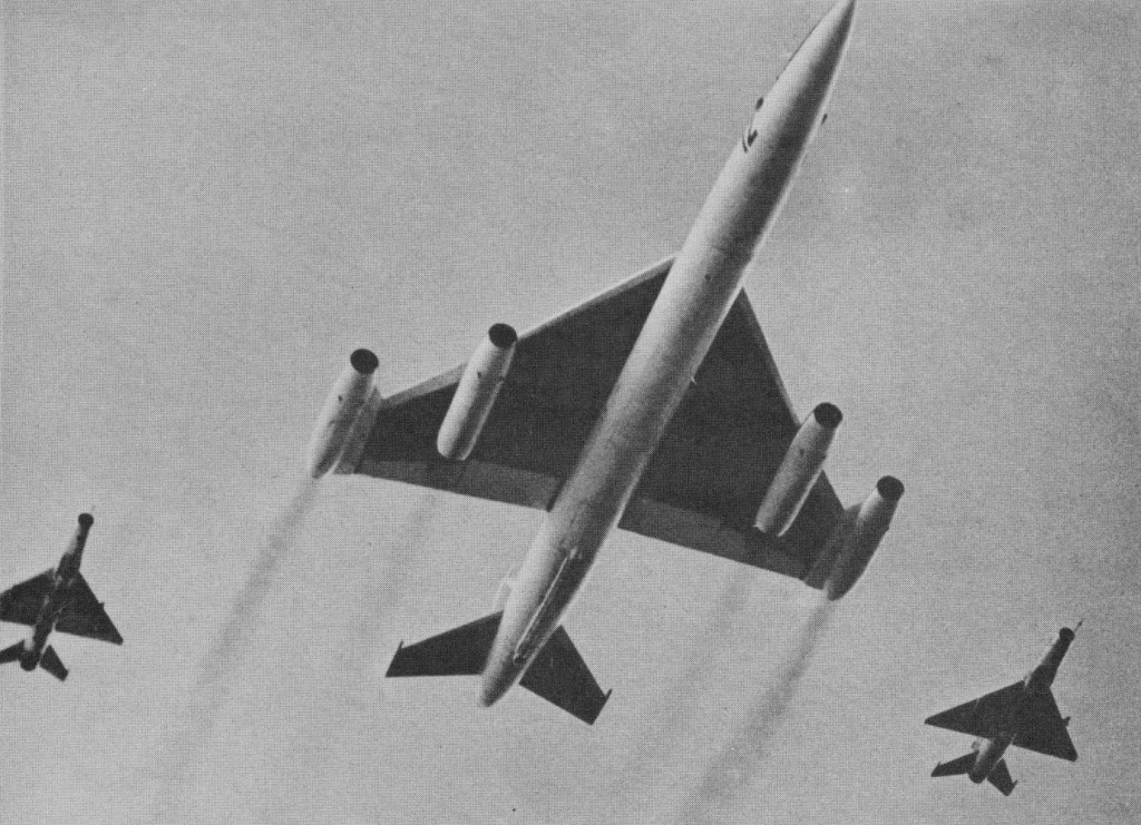
First flight dates between 1957 and 1961 have been quoted, and it is believed that a maximum speed in the order of Mach 1.8 was achieved. By the standards of the day this was a good figure, but the range of 3730 miles (6000 km) without payload was poor. It was seen at the 1961 Soviet Aviation Day display.
The last of several prototypes, generally known as the M-52, had a different powerplant arrangement: the two inboard engines remained on underwing pylons. The M-52 was powered by four Kolesov ND-7F or VD-7F turbojets, with an afterburning thrust of 18145kg. The two outboard engines remained non-afterburning units but were arranged on pylons with forward-swept leading edges projecting horizontally from the cropped tips of the delta wings. The M-50/M-52 series failed to progress past the prototype stage. The Bounder was intended to carry a weapons load of up to 20,000kg.
M.50 Engines: 2 x 14500kg Kolesov VD-7F and 2 x 12260kg VD-7 turbojets Wingspan: 37.0 m / 121 ft 5 in Length: 57.0 m / 187 ft 0 in Height: 12.0 m / 39 ft 4 in Wing area: 282.0 sq.m / 3035.42 sq ft Max take-off weight: 200000 kg / 440927 lb Empty weight: 74500 kg / 164245 lb Max. speed: 1053 kts / 1950 km/h / 1212 mph Cruise speed: 1500 km/h / 932 mph Ceiling: 20000 m / 65600 ft Range w/max.fuel: 6000 km / 3728 miles Armament: 20000kg of bombs and missiles Crew: 2
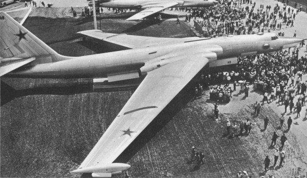
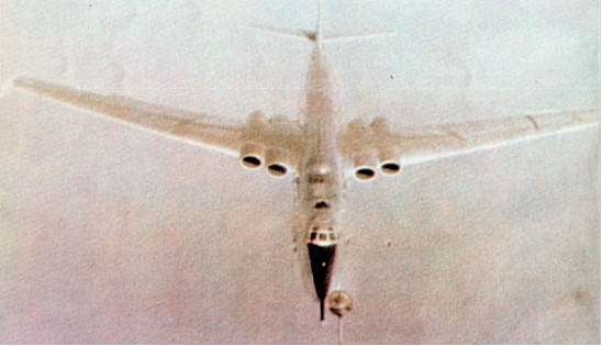
In 1951 V. M. Myasishchyev was directly ordered by Stalin to build a jet bomber to fly long range strategic missions. The Myasishchyev M-4 (often called the Mya 4, and called Molot, meaning hammer, by the Soviets, and given the codename ‘Bison’ by NATO) proved successful.
A mid-wing cantilever monoplane with a deep section swept wing, the M-4 has a tail unit with all-swept surfaces, and retractable landing gear comprising two main units in tandem on the fuselage centreline, each with a four-wheel bogie, plus twin-wheel outrigger balancing units which retract into the wingtips. The circular-section fuselage incorporates a pressurised nose compartment and tail turret for the crew, and a large internal weapons bay in the lower fuselage between the main landing gear units. The powerplant comprises four turbojets buried in the wing roots, these being initially Mikulin AM-3Ds each of 8700kg thrust.
Following its maiden flight in late 1953, a single example of this large aircraft took part in the 1954 May Day parade fly past over Moscow, its size being gauged from the escorting MiG fighters. It was expected to appear in large numbers, but little was heard of it for years. In fact a useful run of about 150 had been delivered, at first being used as free fall bombers (Bison A), reaching regiments of the DA (Long Range Aviation) in 1956. Altogether about 200 were built. By 1959 the Mya-4 bombers were being fitted with more powerful engines, and their role changed from bomber to long-range over-sea reconnaissance, ECM and, in some cases, flight-refuelling tanker. Many were given different noses as ‘Bison B’ and ‘Bison C’ for maritime reconnaissance purposes. All aircraft were given large fixed FR probes, the rear turrets were removed and a vast amount of special reconnaissance equipment fitted, with from five to 17 aerials visible all over the aircraft.
In the Bison C- sub-type a large search radar fills the entire nose, lengthening the nose by about 6 ft and changing its shape. Since 1967 these now obsolescent aircraft have been frequently encountered on probing missions far over the Arctic, Atlantic, Pacific and elsewhere, at both high and very low levels, the C-model having been seen most frequently.
Bison C
In 1983 it was estimated that 43 remained in active service in the original role. Supporting them are another 30 rebuilt as inflight-refuelling tankers, with many modifications including a large hose drum unit in the rear of the weapon bay. ‘Bison B’ was a long range maritime reconnaissance version, possibly re-built from the original bomber, with a ‘solid’ nose housing a mapping and ship targeting radar with the refuelling probe above. Numerous other reconnaissance systems were installed. ‘Bison C was an improved maritime reconnaissance version with an even larger surveillance radar (NATO name ‘Puff Ball’) in a more pointed nose swollen at the sides and with the refuelling probe at the tip. These flew surveillance and electronic missions for the AV MF (Naval Air Force).
In all about 150 were built.
About 40 tanker/transport versions of the M-4 were estimated to remain in service in 1992. These were to be replaced by II-78 ‘Midas’ tankers.
M-4 / 3M Engines: 4 x VD-7, 107.8kN Max take-off weight: 202000 kg / 445336 lb Empty weight: 74430 kg / 164091 lb Wingspan: 50.53 m / 165 ft 9 in Length: 51.70 m / 169 ft 7 in Wing area: 340.0 sq.m / 3659.73 sq ft Max. speed: 940 km/h / 584 mph Ceiling: 12150 m / 39850 ft Range: 11850 km / 7363 miles Endurance: 15 hr Armament: 6 x 23mm cannons, 24000kg of bombs and missiles Crew: 8
Bison A Type: heavy bomber Engines: 4 x Mikulin AM-3D single-shaft turbojets, 19,180 lb (8700 kg). Estimated, span 165 ft 7½ in (50.48 m) Estimated Length 154 ft 10 in (47.2 m) Estimated height 46 ft (14.1 m) Estimated empty 154,000 lb (70,000 kg) Estimated maximum loaded 352,740 lb (160,000 kg) Estimated Max speed 560 mph (900 km/h) Estimated Range 6,835 miles (11,000 km) with 9,920 lb (4500 kg) of bombs or electronic equipment. Service ceiling 42,650 ft (13,000 m) Armament: ten 23 mm NR-23 cannon in manned turret in tail and four remotely controlled turrets above and below front and rear fuselage (two guns in each turret); internal bomb bays in tandem for at least 22,050 lb (10000 kg) stores.
Bison B Type: strategic reconnissance and ECM Engines: 4 x D-15, 28,660 lb (13,000 kg) Estimated empty 176,400 lb (80,000 kg) Estimated maximum loaded 375,000 lb (170,000 kg) Estimated Max speed 560 mph (900 km/h) Estimated Range 6,835 miles (11,000 km) with 9,920 lb (4500 kg) of bombs or electronic equipment. Service ceiling 49,200 ft (15,000 m) Armament: six 23 mm cannon in two forward turrets and tail turret, internal bay for at least 10,000 1b (4500 kg) stores. In many versions a single 23 mm gun is fixed on the right side of the nose, firing ahead.
Bison C Type: multi-role reconnaissance bomber Engines: 4 x D-15, 28,660 lb (13,000 kg) Estimated empty 176,400 lb (80,000 kg) Estimated maximum loaded 375,000 lb (170,000 kg) Estimated Max speed 560 mph (900 km/h) Estimated Range 6,835 miles (11,000 km) with 9,920 lb (4500 kg) of bombs or electronic equipment. Service ceiling 49,200 ft (15,000 m) Armament: six 23 mm cannon in two forward turrets and tail turret, internal bay for at least 10,000 1b (4500 kg) stores. In many versions a single 23 mm gun is fixed on the right side of the nose, firing ahead.
M-4 Bison E Type: six seat strategic bomber Engines: 4 x 9500 kg (20,943 lb) thrust Mikulin RD 3M turbojets Max speed at high alt: 1000 km/h (621 mph) Service ceiling at normal loaded wt: 17000 m (55,775 ft) MTOW Service ceiling: 13000 m (42,650 ft) Range 10700 km (6,650 miles) Empty wt: 70000 kg (154,321 lb) Normal loaded wt: 160000 kg (352,734 lb) MTOW: 210000 kg (462,963 lb) Wing span: 50.48 m (165 ft 7.5 in) Length (no probe): 47.20 m (154 ft 10 in) Height: 14.24 m (46 ft 0 in) Wing area: 309.0 sq.m (3,326.2 sq ft) Armament: (as built) 10x 23 mm cannon in five power turrets; internal bomb bay for 15000 kg (33,068 lb) bombload.
The MTU Turbomeca Rolls-Royce MTR390 is a turboshaft developed for light helicopter applications by MTU Turbomeca Rolls-Royce (MTR). The engine is designed to power helicopters in the weight range of 5-7 tonnes in both single and twin engine configurations. So far the only application is the Eurocopter Tiger. Test runs of the MTR390 began in 1989 and the first test flight was performed in 1991. The MTR390 received military certification in May 1996 and civil approval in June 1997. An uprated version, the MTR390-E (Enhanced), was being developed with Spain’s ITP.
Applications: Eurocopter Tiger
Specifications: MTR390 Type: Centrifugal Turboshaft Length: 42.4 in (108 cm) Diameter: 26.8 in (68 cm) Dry weight: 372 lb (169 kg) Compressor: Centrifugal, 2 stage Combustors: Annular Turbine: 1 stage high pressure turbine, 2 stage low pressure turbine Maximum power output: 1465 shp Overall pressure ratio: 13:1 Specific fuel consumption: 0.46 lb/shp-hr
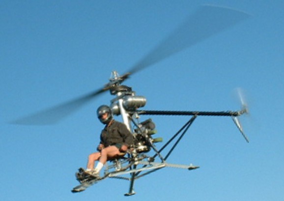
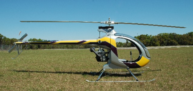
The ultralight Mosquito is one of the worlds lightest manned Helicopters that was designed and developed over 10 years to deliver performance, relability and easy of flight. The original prototype has been flying since 1994 and meets the ultralight Part 103 requirements.
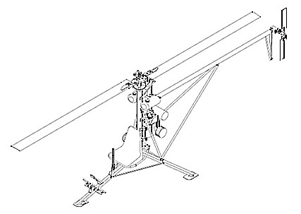
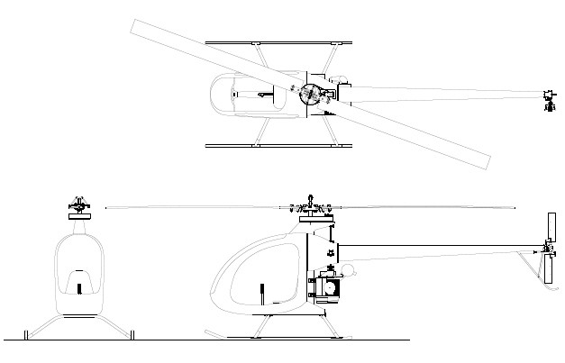
The Mosquito frame is made up of Aircraft Grade 6061-T6 aluminum and utilises a simple triangulated structure with straight tubing throughout to maximize strength, reduce weight and simplify construction. The additional use of a Carbon Fibre tail boom and support struts adds to the Mosquito’s structural ridgidity. The Mosquito’s tripod legs are equiped with small skid pads to help reduce lateral movement during engine run-up to lift off stage. Ground handling wheels are also available to easy ground transport.
The Mosquito is powered by Compact Radial Engine’s – MZ202, 60-hp, a two cycle, two cylinder engine. This engine empolys Reed Induction which yields a very flat torque curve ensuring power is delivered constantly over the required operating range. The MZ202 also has a lower operating speed of 6000 rpm resulting in less stress on the engine and improving reliability. The complete engine package only weighs 69 pounds and comes with a 180-watt alternator that provides power to run the electrical system which also features and an electric start system.
Mosquito
The primary reduction is bolted directly to the engine. A centrifugal clutch on the engine crankshaft permits startup of the engine without the load of the rotor. Power is transmitted from the clutch to the driven pulley of the reduction through an HTD cog belt. The driven pulley houses the sprage clutch, which permits the rotor to overspeed the engine during autorotation.
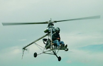
The Mosquito XE is the same aircraft, but the open frame tubing has been replaced with an all fiberglass closed in design. The XE airframe is a unibody construction made entirely of high quality fiberglass in a vinylester matrix. Power is provided by the same Compact Radial Engines MZ202 used for years on the open version of the Mosquito. This two cylinder, two stroke engine has a power output of 60hp, ample to do the work for its 610lbs of gross weight.
Mosquito XE
The power train, controls and rotor systems have been through some minor modifications to suit the XE design. The collective control has been adjusted to adapt to the different mounts in the XE. The main rotor blade diameter has increased by 1.5 ft to account for the additional gross weight. The Mosquito XEL is the same as the XE but is equipped with floats.
Materials provided with the kit include fiberglass airframe parts, machined parts, instruments (Rotor/Engine Tach, redundant digital engine tach with hour meter, dual EGT/CHT, Airspeed Indicator), rotor blades and engine. Many of the airframe parts are already joined. The builder needs only to bolt and rivet the final major components together.
A comprehensive assembly manual is provided along with a full set of part and assembly drawings as well as exploded view drawings. Builder assistance can be provided by phone or email. It requires around 250 to 300 hours of build time. Standard shop tools are required to cut and form some of the simple frame and control parts and for bolt and rivet assembly. A quick build parts set, in which all the parts nomally fabricated and formed by the builder are already finished, is available to save more build time. A small amount of welding is required on the exhaust system.
Optional extras to consider with purchase of the Mosquito include factory paint, tail fins, ceramic pistons, seat covers, governor kits, wheel kits and quick build parts. The Mosquito XE can be ordered in several stages of kit. The 1st kit includes the materials and components for building the composite airframe. This group consists of the composite enclosure, fuel tank, tail boom, landing gear and the full Builder’s Set of Plans and Instructions. The kit is designed to meet the 51% rule. The 2nd kit is for the cyclic, collective, torque tubes, push-pull tubes, swash plate, and rotor controls. The 3rd is the power drive system consisting of primary and secondary reduction units, sprague clutch, engine coupling shafts, tail rotor drive shaft components, gear boxes, main rotor shaft assembly, and associated bearings, couplings, etc. and the 4th group includes the engine, battery, centrifugal engine clutch, fuel tanks, fuel valves, fuel lines, throttle, switches, wiring, and instruments. The final stage is the assembly of the rotor heads, the tail rotor blades, and main rotor blades but the manufacturer likes to see you have some training under your belt before finishing this stage and being tempted or hurried to get airborn.
Delivery on complete kits is around 6 months from placing a deposit, or around 2 months for a kit group, depending on factory demand at the time.
Total Kit Price: US$17,495 after US$2,000 training rebate in 2009.
Mosquito Engine: Compact Radial Engines MZ202, 2 cylinder, 2 stroke, 60 HP (45kW) Frame Length: 16 ft. Overall Length: 20 ft Width: 72 in. Height: 83 in Main Rotor Diameter: 18 ft Tail Rotor Diameter: 40 in. Empty Weight: 254 lb. Gross Weight: 530 lbs Useful (Pilot) Load: 250 lbs Fuel Capacity: 5 US gallons Main Rotor Speed: 540 rpm Tail Rotor Speed: 2500 rpm Fuel Flow at Cruise: Approximately 4.5 U.S. Gallons per hour Flight Duration: Approx. 60 min. Hover in ground effect: 8,000 ft. (estimated) Hover out of ground effect: 6,500 ft. (estimated) Max Speed: 70 mph
Mosquito XE Frame Length: 16 ft Overall Length: 20 ft Width: 72 in Height: 84 in. Main Rotor Diameter: 19.5 ft Tail Rotor Diameter: 40 in. Empty Weight XE: 298 lb Gross Weight: 610 lbs Useful (Pilot) Load: 240 lbs. Fuel Capacity: 12 US gallons Engine: Compact Radial Engines MZ202, 2 cylinder, 2 stroke 64 HP (45kW) Electrical System: 12 volt DC battery, starter, 180 watt alternator Main Rotor Speeds: 540 rpm Tail Rotor Speeds: 2500 rpm Fuel burn: 4.5 gph Range: 150 miles Hover in ground effect: 8,000 ft. (estimated) Hover out of ground effect: 6,500 ft. (estimated) Max Speed: 80 MPH Price: $30,000 including engine/instruments (2009)
Mosquito XEL Frame Length: 16 ft Overall Length: 20 ft Width: 72 in Height: 84 in. Main Rotor Diameter: 19.5 ft Tail Rotor Diameter: 40 in. Empty Weight XEL: 312 lb Gross Weight: 610 lbs Useful (Pilot) Load: 240 lbs. Fuel Capacity: 5 US gallons Engine: Compact Radial Engines MZ202, 2 cylinder, 2 stroke 64 HP (45kW) Electrical System: 12 volt DC battery, starter, 180 watt alternator Main Rotor Speeds: 540 rpm Tail Rotor Speeds: 2500 rpm Fuel burn: 4.5 gph Range: 60 miles Hover in ground effect: 8,000 ft. (estimated) Hover out of ground effect: 6,500 ft. (estimated) Max Speed: 80 MPH Price: $31,000 including engine/instruments (2009)
Mosquito XE3 Frame Length: 16 ft Overall Length: 20 ft Width: 72 in Height: 84 in. Main Rotor Diameter: 19.5 ft Tail Rotor Diameter: 40 in. Empty wt: 360 lb Gross wt: 720 lb Useful load: 290 lb Fuel Capacity: 12 gal Range: 150 miles Cruise spd: 80 mph Max spd: 100+ mph Fuel burn at cruise: 5 gph Engine: CRE MZ301 3 cyl 2 cycle Power 85 hp Main Rotor RPM: 590 Tail rotor rpm: 2500 Hover in ground effect 9500 ft (est) Hover out of ground effect 7500 ft (est) Price: $36,000 including engine/instruments (2009)
Mosquito XET Frame Length: 16 ft Overall Length: 20 ft Width: 72 in Height: 84 in. Main Rotor Diameter: 19.5 ft Tail Rotor Diameter: 40 in. Empty wt: 433 lb Gross wt: 820 lb Useful load (with optional aux tank): 240 lb Useful load (without optional aux tank): 290 lb Fuel capacity: 12 gal Aux tank capacity: 8 gal Range (with aux tank): 160 miles Cruise spd: 80 mph Max spd: 100+ mph Fuel burn at cruise: 8.5 gph Engine: Solar T62-2A1 turbine Power: 90 hp Main Rotor RPM: 590 Tail Rotor RPM: 2500 Hover in ground effect 9000 ft (est) Hover out of ground effect 7000 ft (est) Price: $37,000 excluding engine (2009)