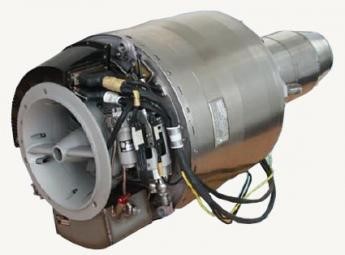
Development of the TJ 100 turbo-jet engine began in 2002, as a drive unit for MAE UAV and piloted flying vehicles.
The TJ 100 is single-shaft engine with single-stage radial compressor, annular combustion chamber, single-stage axial turbine, and stationary exhaust jet.
In the compressor intake there is a brushless starter generator, which enables the starting from the board network and power generating in course of the engine operation.
The intake air is compressed in the radial compressor wheel, proceeds through radial and axial diffuser into the combustion chamber, where it is mixed with fuel sprayed by several fuel nozzles. Combustion gases arising in fuel burning in the combustion chamber expand through the single-stage axial turbine and exhaust jet into the atmosphere.
The rotor of the engine is mounted on 2 ball bearings lubricated with pressure oil.
Several versions were produced, varying by length of output nozzle, mounting, and by power.
PBS produce TJ 100, TJ 100C, TJ100E, and TJ 100I of 100 daN (225 lbf) power. The TJ 100A and TJ 100S are produced with 110 daN (247 lbf) power.
Static Thrust: 100 daN / 225 lbf Spf. Fuel Consumption: 1.2 kg/daN.hr / 1.2 lb/lbf.hr Oil Consumption: 180 ml/hr / 0.16 qt/hr Electric Power Output: 28 V/800W Weight – Engine: 16 kg / 35 lb Weight – Wth/Access: 19 kg / 41 lb Outside Diameter: 272 mm / 10.7 in Length: 485 mm / 19 in Fuel Consumption: < 128 kg/hr / < 281 lbs/hr Max Running Altitude: 8 000 m / 26 246 ft
PBS TJ-100 E3S Max Thrust (max 5 min.): 258.53 lbf [1150 N] Electric Power Output: 650 W Specific Fuel Consumption (max thrust): < 1.1376 lb/lbf/hr Fuel Consumption at Idle: 11 gal/hr Outside Diameter: 10.7″ Engine Length: 24.6″ Engine Weight: 43 lbs Max Operating Altitude: 32,808 ft. msl Max Starting Altitude: 19,685 ft. msl Flight Speed Range: 0 to 0.8 mach Speed Range for Startup: 0 to 0.6 mach Fuel Requirements: JET-A, JET-A1, JP4, JP8, TS-1, T2, RT Lubrication: according to MIL-L-23699 (Mobil Jet Oil II, Aeroshell 560) Price 2020: $65,000
První Brnenská Strojírna Velká Bíteš, a.s./ PBS is a manufacturer of: Small aircraft turbojet engines and auxiliary power units, Environmental control systems for aircraft and helicopters, Ground power units, Precise castings for automotive, aerospace and glass industries and healthcare, Complex and completely machined parts of electromotors, alternators, mammographs and wind power plants, Decanting centrifuges for sewage plants, i.e. programs closely related to ecology and environmental protection.
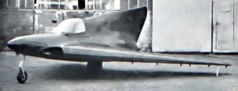
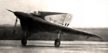
Designd by Nicolas Roland Payen, Flechair Sa built Payen’s Pa.49 experimental jet-powered delta-winged aircraft. In May 1951, three workers directed by Payen built the all-wood PA-49 in a month. Reportedly named after Roland Payen’s youngest daughter.
It has a triangular shape or Delta wing, 2.7 m swallow tail. The wing has 72 ° sweep, is 11,250 m² with a wingspan of 5.6 m. This wing has no dihedral. The average profile is a modified NACA the 230000 series. The structure of the wing is built in one piece. The trailing edge has flaps in the central part, equipped with tabs controlled in flight. The control surfaces are statically and dynamically balanced. The structure of the wing, is composed mainly of a working chamber, formed by the assembly of two perpendicular rails and oblique side rails symmetrically joined by two ribs. All wing spars or fins, main or joint, and ribs are made of box spruce (laminated strips) and birch plywood.
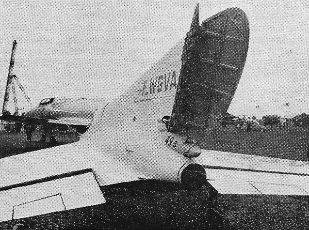
While the Pa-49’s inboard elevators and outboard ailerons functioned separately, the rudder doubled as a speedbrake.
The Pa-49 strengthened surfaces ‘split’ open to act as air brakes. This solved the problem of interference between the braking and directional controls on an all-wing aircraft.
It is equipped with a Turbomeca Palas turbine engine. The Turbomeca Palas turbojet engine weighed 159 pounds and producied approximately 330 pounds of thrust, it drew air in through dual intakes at the junction of the wing’s leading edge and fuselage.
Originally designed with a bicycle landing gear that incorporated wing-tip skids, the Pa-49 ultimately flew with fixed tricycle gear.
It was not until the end of 1952 and negotiation for the PA-49 to undergo testing in the wind tunnel of ONERA Chalais-Meudon.
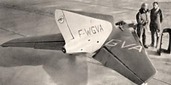
First flown on January 22, 1954, by Tony Ochsenbein, the PA49 was the first French delta-wing aircraft.
The endurance of just over one hou was entirely sufficient for short test flights. It was also sufficient for flights to various airshows and industry expositions, where the aircraft was photographed on several occasions, both on static display and in flight.
Between 1954 and the end of 1958, it made many flights before the project became inactive.
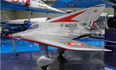
Payen Pa-49B Katy
Fortunately, the Katy survived 300 test flights unscathed, and Payen ultimately donated it to the Musée de l’Air et de l’Espace in Paris, where it remains on display today.
Engine: one Turbomeca Palas of 330 lb thrust Wingspan: 16 ft 11 in Length: 16 ft 8 in Height: 7 ft 2 in Empty weights: 1,005 lb Max all-up weight: 1,430 lb Maximum speed: 310 mph Cruise speed: 217 mph Landing speed: 67 mph Initial rate of climb: 1,150 ft/min Ceiling: 27,880 ft Endurance: just over 1 hr Accommodation: single-seat
The requirement for a new multi-role combat aircraft (MRCA) to equip the German Luftwaffe and Marineflieger, Italy’s Aeronautica Militare and the UK’s RAF was established in the mid-1960s. This led, on 26 March 1969, to formation of the European industrial company Panavia Aircraft GmbH, combining the aviation talents of Aeritalia, British Aerospace and Messerschmitt-Bölkow-Blohm to design, develop and manufacture this important aircraft. The feasibility study for an aircraft to meet the tri-national requirements was completed by 1 May 1969, and within four years a go-ahead for the Panavia MRCA was given; between then and the flight of the first prototype (D-9591), flown at Manching, Germany on 14 August 1974, piloted by the project test pilots, Paul Millett with Nils Meister in the second seat. This is the first of nine prototypes and six pre-series aircraft to fly. Two more prototypes were to fly at Warton, one at Manching and one at Caselle.
The initial production agreements for the Tornado envisage a total of 809 aircraft and comprise 644 of the (IDS) interdictor/strike version for the Aeronautica Militare (100), Luftwaffe (212), Marineflieger (112), and RAF (220), plus an additional 165 examples for the RAF of the air-defence variant (ADV, first flown in October 1979).
The aircraft has variable geometry wings and is powered by two Turbo-Union RB199-34R turbofans, with a maximum speed of 1452 mph and a service ceiling of 50000 feet. The Air Defence Variant (ADV) version of the Tornado is optimised for long-range interception with radar and infra-red guided air-to-air missiles and one internally mounted 27mm Mauser cannon.
Compared to the initial IDS variant, the Tornado ADV has a longer fuselage with additional fuel capacity, a better fineness ratio for enhanced transonic acceleration, and the possibility of locating four Sky Flash air-to-air missiles in semi-recessed positions in the lower fuselage.
Tornado ADV
The air defense variant (ADV) of Tornado, developed specifically for the RAF as a long-range air defense interceptor has GEC-Marconi Foxhunter multimode radar in place of the IDS’s ground-mapping radar and terrain-following radar, although some 80 percent commonality was achieved between the types.
The first production IDS versions were flown, chronologically, by the UK (10 July 1979), West Germany (27 July 1979) and Italy (25 September 1981), early production aircraft going to the Trinational Tornado Training Establishment (opened in 1981) which was set up at RAF Cottesmore and which, by August 1982, had received its full complement of 50 aircraft. The RAF also has a Tornado Weapons Conversion Unit (TWCU) at RAF Honington, the other three services each conducting their own weapons conversion training with national avionics and weapons.
The first of 229 Tornado GR.1 strike aircraft was delivered to the Royal Air Force in 1981 and the first squadron equipped with the aircraft became operational in 1982. The GR.1 is capable of carrying a wide range of armaments, including conventional and anti-airfield bombs, laser-guided bombs, air-to-ground rockets and anti-radar missiles.
Early tests carried out in 1980 showed that the aircraft’s weapon system was capable of highly accurate bomb delivery, and this has been confirmed more recently by Tornados competing for the first time in the USAF’s 1984 ‘Giant Voice’ bombing competition held in South Dakota. Tornado GR.Mk1s of No. 617 (Dambuster) Squadron, competing against Boeing B-52s and General Dynamics FB-111As of Strategic and Tactical Air Commands, and RAAF F-111Cs, took first and second place in the LeMay Trophy contest (high-and low level sorties) first and third places in the John C. Meyer Trophy contest (for the best non-B-52 crew in low-level attack) and second and sixth place in the Mathis Trophy contest (for the best high and low-level team bombing scores). This is the first time that teams from outside the US have won the LeMay or John C. Meyer trophies, and such capability augurs well for the Tornado and NATO.
Features of the design include a variable geometry wing, sweeping from 25′ to 68′, two RB199 three-shaft turbofans developed by Turbo-Union, (which combines Fiat Aviazione, MTU München and Rolls-Royce) and, because of the trinational requirement, some variations in avionics and communications equipment.
This advanced equipment provides each nation with an aircraft having day and night all weather extremely low-level interdictor/ strike capability, the RAF designating this version Tornado GR.Mk1.
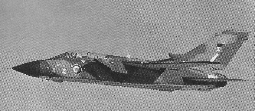
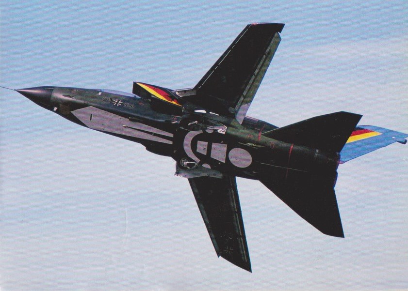
The first prototype of the RAF’s ADV variant, designated Tornado F.Mk2, was flown first on 27 October 1979, and this differs structurally in having the overall length being increased by 4 ft 5.5 in (1.36 m) to permit tandem carriage of AAMs, and the fixed portion of the wings being extended forward, increasing chord. Increased internal fuel capacity, plus drop tanks on the inner underwing stations, allowed one of the prototypes to demonstrate a 2 hours 20 minutes combat air patrol (CAP) on station 374 miles (602 km) from base, but a nose-mounted (port) retractable inflight-refuelling probe will allow more extended CAPs. Armament of this version comprises a 27-mm IWKA-Mauser cannon in the fuselage, plus two AIM-9L Sidewinder (underwing) and four Sky Flash (underfuselage) air-to-air missiles. The first two Tornado F.Mk2s for RAF service were handed over to the F-2 Operational Conversion Unit at RAF Coningsby, Lincolnshire in early November 1984.
Tornado F2A
Apart from dual controls and minor differences in the navigator’s equipment, the trainer Tornadoes are identical to the strike aircraft and possess full operational capability.
A total of 929 Tornados has been ordered in seven batches for the air arms of the three partner countries and two export custom¬ers. In addition, four development aircraft will be reworked to production standard. Production in Italy was completed by 1987, but continues at a rate of 44 per year in the UK and 42 per year in Germany. By mid-1987 620 aircraft had been delivered. Two basic versions are in production:
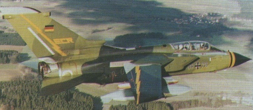
IDS The sixth batch of aircraft already incorporates some avionic upgrades, including the MIL standard 1553B digital databus, uprated mission computers, and missile control systems associated with the integration of Alarm (for the RAF) and AGM-fl 85 Harm (for West Germany). The Luftwaffe selected the electronic, combat, and reconnaissance (ECR) variant of the IDS Tornado in 1986, and placed an order for 35 aircraft. Optimised for the stand-of reconnaissance and anti-radiation roles, the ECR will feature an emitter locator system, a datalink, a low/medium altitude recon¬naissance system, and jammer pods. Normal weapons load will comprise two Harms and two Sidewinder AAMs, with ECM/flare dispenser and external fuel tanks. The twin Mauser 27mm guns are omitted.
ADV The first prototype of the Tornado Air Defence Variant, A01 s/n ZA254, com¬pleted more than 41 hr flying by the end of January 1980 when it went on lay up for the installation of updated equipment. The aircraft made its first flight on 27 October 1979. Early ADVs were fitted with RB.199 Mk.1OU engines and designated F.2s, while the 1987 production model is the F.3 with Mk.104 engines and other equipment upgrades. F.2s will be retrofitted to F.3 standard except for the engine change, and will be known as F.2As. Designed specifically to meet RAF require¬ments for a long-range all-weather interceptor, the Tornado ADV features an advanced track-while-scan pulse-Doppler radar, twin inertial platforms, an updated main computer, advanced displays, and (on the F.3) automatic wing sweep and the automatic manoeuvre device system which controls flap/slat scheduling. Initial armament consists of mixed of Skyflash and Sidewinder AAMs.
The RAF’s first Tornado fighter squadron, No. 29, was equipped with Tornado F.3s, the definitive version powered by RB.199 Mk.104s and carrying four Sidewinders (instead of two as on the F.2) plus four Sky Flash missiles.
The 1990 cancellation of 33 Tornados for the RAF meant that production was likely to end in 1992. To 1990, more than 900 Tornados had been ordered for the air arms of the three partner countries and Saudi Arabia, with other export orders in abeyance. As well as operating the IDS attack version, the Luftwaffe is receiving 35 electronic, combat and reconnaissance (ECR) variants. Four Skyflash AAMs, Sidewinders and a 27mm cannon armament.
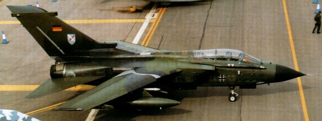
The ECR (electronic combat and reconnaissance) version was a Tornado variant developed by the Germans for the reconnaissance role and suppression of enemy air defense with the AGM-88A HARM anti-radar missile.
Tornado ECR
The first production Tornado ECR flew on 26 October 1989.
44+00 JBG-31, 28 Aug 1988
The RAF received 170 ADVs, of which 152 were in F.Mk 3 improved form. Saudi Arabia was the only other customer, having 24.
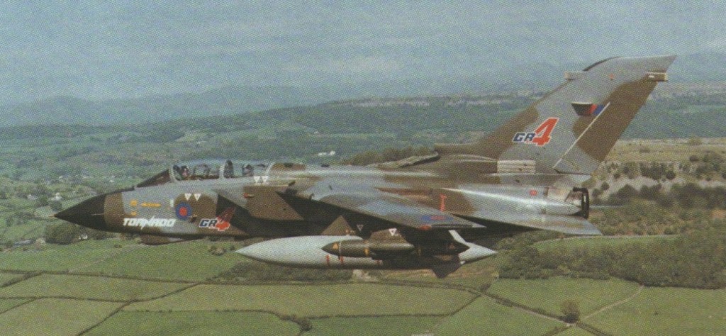
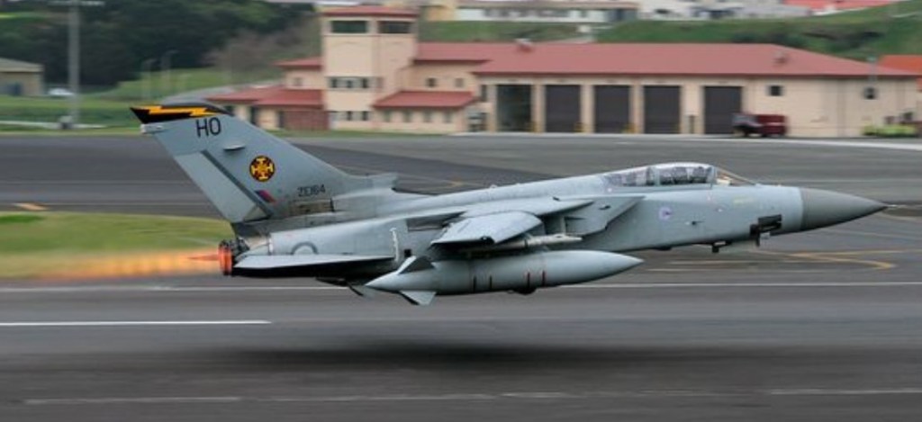
GR.1 is the RAF designation for the RAF Tornado IDS aircraft. The GR.1A was a modified variant optimized for the recconnaisance role and the GR.1B for the maritime attack role equipped with Sea Eagle missiles. Intended as a mid-life update of the Tornado GR.1 fleet, deliveries of the Tornado GR.4 began in October 1997. All GR.1 and GR.1B aircraft that remained in service were upgraded to GR.4 standard. All GR.1A have been upgraded to GR.4A, the reconnaissance version of the GR.4. The GR.4/4A update enables the RAF Tornado IDS aircraft to remain in service for at least another 10-15 years. While the performance of the aircraft is similar, overall effectiveness is enhanced by a forward–looking infra-red system, a wide-angle head-up display, night vision goggles, new defensive systems and avionics and provision for enhanced anti-armour, stand-off attack and laser designation weapons.
A ceremony was held at Warton on June 10, 2003 to celebrate the hand over by BAE Systems of the 142nd and last Tornado GR.4 to the RAF. Over £1bn has been spent on this Mid Life Update which began with contract signature back in July 1994. The first air¬craft was delivered on October 31, 1997, though since then the time needed to do the work on each aircraft has been reduced by 40%. One of the aims of the modification of the GR.1 and GR.1A into the GR.4 and GR.4A respectively has been to give the RAF a common fleet standard. The aircraft is now able to carry more smart weapons such as the Storm Shadow cruise missile as well as use the RAPTOR reconnaissance pod. Other major improvements include a Forward Looking Infra Red (FLIR) sensor, new Head Up Display (HUD), NVG compatible cockpit, GPS navigation, provision for a TIALD pod and new electronic warfare system.
Tornado GR.4
Until delivery of the final aircraft was in 1998, orders covered 781 production IDS Tornadoes for interdictor strike and ECRs for electronic combat and reconnaissance, as 228 IDSs for the RAF, 210 IDS and 35 ECR for the Luftwaffe, 112 IDSs for the German Navy, 99 IDSs for the Italian Air Force, and 96 IDSs for Saudi Arabia.
During the 1991 Gulf War, the Tornado GR.1 force flew 1500 operational sorties mainly against airfields, air defence sites and bridges. Six aircraft were lost in low-level missions.
Germany’s Mid Life Update (MLU) for the Tornado was completed. And also the Italian Air Force (AMI) Tornado IDS and ECR were scheduled to receive a mid life update. AMI Tornado F.3s that were leased from the RAF were returned to the UK, and were to be replaced by leased F-16s until the arrival of the Eurofighter Typhoon.
The UK’s Ministry of Defence was pioneering an approach to building its next-generation Tempest fighter—by recycling retired Tornado jets. Instead of sourcing expensive foreign materials, old fighter jet parts are ground into a titanium-rich powder used for 3D printing new aircraft components. Rolls-Royce has successfully tested these parts in an Orpheus engine, proving their viability. This initiative not only reduces costs but also strengthens supply chain resilience. With Italy and Japan also involved, the Tempest program is set to revolutionize sustainable aircraft manufacturing, with a planned first flight in 2026 and entry into service by 2035. While this approach might sound crazy, it actually reduces the country’s reliance on foreign-sourced materials and points toward some incredible new ways to recycle old aircraft. Introduced as a response to lingering concerns about how the global market for vital materials could be impacted by large-scale war between great powers, this is an area of increasing focus for the Future Combat Air Systems (FCAS) program. The FCAS is Britain’s overarching effort that includes the development of the crewed Tempest fighter. “Through the expected lifecycle of the U.K.’s FCAS, we expect access to critical materials to be challenged, as global supply chains become increasingly disrupted and competitive. In parallel, there is a societal need to make the best use of the raw materials we already have,” explained the Future Combat Air System’s Sustainability Requirements Manager, identified only as “Squadron Leader Rob.” To achieve this, rather than just scrapping old Tornado GR4s that were retired from active service in 2019 and then sourcing all the high-quality raw materials needed for the new Tempest fighter program from foreign countries, the U.K. will simply yank parts off of those old Tornados and feed them into an industrial grinder to produce a powder, called “feedstock.” This powder can then be used by industrial 3D printers to produce new components for new fighters. The British Ministry of Defense, is collaborating with Rolls Royce in the effort. In testing so far, Tornado engine compressor blades, which include a high quantity of titanium, were cleaned, ground up, and then used to 3D print a new nosecone and compressor blades for “Orpheus” the small engine Rolls Royce has in testing to mature technologies for the Tempest program. With its new 3D-printed component, the Orpheus engine was then put through the wringer and managed to pass all suitability and safety tests.
“Tornado 2 Tempest is a bold, exciting and innovative project and a demonstration of how excellent collaboration between the MOD, industry and SME can deliver sustainable and technologically advanced solutions,” said Andrew Eady, Rolls-Royce Vice President for FCAS Sustainability. This same recycling and 3D-printing process can be used for steel and aluminum components as well, which would further reduce waste, and allow the U.K. to have to mine and process fewer raw materials in the future. “Not only can this solution reduce the costs and burden of sourcing critical and high-value metals, but it can also produce components that are lighter, strong and longer lasting than those made through traditional forging techniques, thereby further enhancing the MOD’s overall sustainability and effectiveness,” Thomas Powell, DRDT’s Strategic & Submarine Recycling Senior Commercial Manager, said in a Rolls Royce press release. Construction of the first Tempest technology demonstrator began 2024, and the U.K., Italy, and Japan, which are also partner countries in the program, are hoping to see the aircraft make its first test flight in 2026, with the goal of getting these fighters into service by 2035.
Tornado ADV Engines: 2 x Turbo-Union RB.199 Installed thrust (dry / reheat): 80 / 142+ kN Span: 13.9 m / 8.6 m Length: 18.1 m Wing area: approx. 25 sq.m Empty wt: 14,500 kg MTOW: 27,968 kg Warload: 8,500 kg Max speed: 2.2 Mach Time to height: 2 min / 9150 m Ceiling: 21,300+ m TO run: 760 m Ldg run: 370 m Fuel approx. internal (external): 7300 lt (6000 lt) Air refuel: Yes Combat radius: 740+ km Armament: 8 x AAM, 1 x 27 mm
Tornado IDS Powerplant: two Turbo-Union RB.199-34R Mk.101 turbofans, 37.70kN (8,475lbst) dry and 66.01kN (14,840lbst) with afterburning Length 16.72m (54ft 10.25in) Height 5.95m (19ft 6.25in) Wingspan at minimum sweep (25 deg) 13.91m (45ft 7.5in) Wingspan at maximum sweep (67 deg) 8.60m (28ft 2.5in) Take-off (’empty’) 14091kg (31,065lb) Max Take-Off Weight 27961kg (61,620lb) Max level speed ‘clean’ at 11000m (36,090ft) Mach 2.2+/ 2337+km/h /1453+mph) Service ceiling 50,000+ ft (15420+ m) Armament: two internal Mauser BK.27 27mm cannons / 180 rounds each Hardpoints: 9 External load: 18,000 lb / 8165 kg Max range: 3885 km Air refuel: Yes Combat radius hi-lo-hi: 1400 km Crew: 2
Tornado IDS Powerplant: two Turbo-Union RB.199-34R Mk.103 turbofans each rated at 38.48kN (8,650lbst) dry and 71.50kN (16,075lbst) with afterburning Length 16.72m (54ft 10.25in) Height 5.95m (19ft 6.25in) Wingspan at minimum sweep (25 deg) 13.91m (45ft 7.5in) Wingspan at maximum sweep (67 deg) 8.60m (28ft 2.5in) Take-off (’empty’) 14091kg (31,065lb) Max Take-Off Weight 27961kg (61,620lb) Max level speed ‘clean’ at 11000m (36,090ft) Mach 2.2+/ 2337+km/h /1453+mph) Service ceiling 50,000+ ft (15420+ m) Armament: two internal Mauser BK.27 27mm cannons / 180 rounds each Hardpoints: 9 Max range: 3885 km Air refuel: Yes Combat radius hi-lo-hi: 1400 km Crew: 2
Tornado F.2 Seats: 2 Wing span: 45 ft 8 in (13.9m)
Tornado F.3 Engines: 2 x 16,910 lb st (71,2 kN) Turbo-Union RB199 Mk103 turbofans Seats: 2 Wing span: 45 ft 8 in (13.9m)
Tornado GR.1 Seats: 2 Wing span: 45 ft 8 in (13.9m)
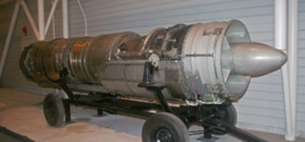
In 1943, Packard leased a government-owned manufacturing plant located on the outskirts of Toledo, Ohio. The plant was previously operated by the defunct Aviation Corporation. Packard used the leased plant to manufacture parts for the Rolls-Royce Merlin engine, and referred to it as its Toledo Division. In the early-summer of 1944, the Army Air Force Material Command contracted with Packard to carry out “advanced aircraft engine development” on both the Merlin and gas-turbine engines. To oversee the new project, Packard hired Allison Engine Company’s Robert M. Williams as their chief design engineer at the Toledo facility in July of that year. In October 1946 Williams and Dr. George F. Wislicenus, one of the engineers working under him, discussed ways of improving the efficiency of turbojet engines. They came up with an engine design which they called a “ducted fan”. The resulting engine was Packard’s model PT-205, with the military designation Packard XJ49-V-1 turbofan engine.
The XJ49 design was a break from conventional design practices of the time. Most turbojet engines then used one centrifugal compressor, one turbine wheel and multiple combustion chambers that resembled long cylinders arranged in a conical pattern. The XJ49 design had a two-stage compressor made up of an axial-flow supersonic compressor at the engine intake, driven by the second power turbine wheel, followed by a spirally-shaped mixed flow compressor, driven by the first turbine wheel, giving an over-all compression ratio of 6:1.
Power from the annular combustion chamber exhaust drives the complex two-stage turbine. The discharge flow from the first turbine stage drives an independent two-stage turbine. The blades of the last stage of the second turbine are extended beyond the engine core to form a supersonic fan that provides air flow around the engine core for additional thrust and further combustion. Supplementary burning (reheat or afterburning) between the two turbines and in the tailpipe can also be used for additional thrust.
The period between drawing up the basic design theory and a having a complete engine ready to make its first run on a test stand was unusually short, as Packard started testing the first (and only) XJ49 in November 1948. When the testing was complete, the XJ49 proved itself to be the most powerful jet engine in operation at the time.
On September 16, 1959 the United States Air Force released the XJ49 engine to the National Air Museum (now the National Air and Space Museum), and is now in storage at their Silver Hill, Maryland facility.
Specifications: XJ49-V-1 Type: Ducted Fan (Turbofan) Compressor: Compound: Two-stage compressor (an axial-flow supersonic 1st stage followed by a mixed flow second stage) Combustors: Annular Turbine: Compound: The gas discharge from the first stage turbine drives the following two-stage turbine. The blades of the last stage of the second turbine section extend outside of the engine core to form a supersonic bypass fan. Maximum thrust: Take-off: 12,000 lb, military: 11,000 lb, normal: 10,000 lb, cruising: 2,560 lb at 35,000 ft. Overall pressure ratio: Over-all pressure ratio of 6:1
In 1943, Packard leased a government-owned manufacturing plant located on the outskirts of Toledo, Ohio. The plant was previously operated by the defunct Aviation Corporation. Packard used the leased plant to manufacture parts for the Rolls-Royce Merlin engine, and referred to it as its Toledo Division. In the early-summer of 1944, the Army Air Force Material Command contracted with Packard to carry out “advanced aircraft engine development” on both the Merlin and gas-turbine engines. To oversee the new project, Packard hired Allison Engine Company’s Robert M. Williams as their chief design engineer at the Toledo facility in July of that year. In early 1945 the Power Plant Lab at Wright Field asked Packard to take on a research project to develop an expendable jet engine of 4,000 pounds thrust weighing no more than 1,000 pounds. Design work for the engine designated as the Packard XJ41 began in May 1945.
After studying existing turbojet engines it was decided to design an engine which would be a significant advancement over conventional turbo-jet engines, have a low manufacturing cost, minimum use of strategic materials and be a light-weight design.
The Packard XJ41 met those requirements with a combination of a mixed flow compressor, a light weight annular combustion chamber and hollow turbine blades for both rotor and stator. The engine’s most outstanding design characteristic was the use of an air inlet that operated at supersonic speed that produced more thrust per pound of weight than designs using low velocity inlet air. The XJ41 weighed 1,100 pounds and produced 4,000 pounds of thrust, where the GE J33 weighed 1,820 pounds at the same thrust. The engine was completed and operating on a test stand on January 8, 1946.
Packard’s investment for production of the new turbojet engine design was extensive. By the end of 1946 the installation of fabrication and testing equipment was valued at $10,000,000. In addition, flight testing, shop and hangar facilities at Willow Run, Michigan was valued at $1,000,000, and an additional $3,500,000 in laboratory and testing equipment was installed by spring of 1947.
Serial numbers V-500001 to V-500007 were allocated indicating that at least seven engines were built. Development continued on the engine over three years, with Packard assigning model numbers PT-103 and PT-104 to military engine designations XJ41 serial number V-500001 and XJ41 serial number V-500003. A design study for an engine suitable for high acceleration, such as a catapult launched take-off, was assigned model number PT-106 in February 1947. Between September 1947 and July 1948 an XJ41 engine attached to a North American B-25J Mitchell bomber was flight-tested several times.
Development of the XJ41 stopped when Packard engineers came up with a radical redesign that differed so much that military model XJ49 was assigned. All work on the earlier design was terminated and funding was transferred to the new design.
Specifications: XJ41-V-500003 Dry weight: 1,100 lb (499 kg) Compressor: single-stage Mixed-flow (combined axial and centrifugal) Combustors: annular combustion chamber Turbine: single stage hollow blades Fuel type: Aviation Kerosene jet fuel Oil system: pressure fed scavenged spray system with dry sump Maximum thrust: 4,000 lbf (18 kN) Thrust-to-weight ratio: 3.64
The Orenda PS.13 Iroquois was an advanced turbojet engine designed for military use. It was developed by the Canadian aircraft engine manufacturer Orenda Engines, a part of the Avro Canada group. Intended for the CF-105 Arrow interceptor, development was cancelled, along with the Arrow, in 1959.
For the CF-105 Arrow project, Avro Canada had originally intended to use one of three different engines, all UK designs: Rolls-Royce RB.106, the Bristol B.0L.4 Olympus, or a license-built version of the Olympus, the Curtiss-Wright J67. The RB.106 and J67 were selected as the primary and backup engines for the new design. However, both the RB.106 and J67 were cancelled during the Arrow’s design phase, too far into the program to select the Olympus. Orenda Engines quickly responded with the PS.13 Iroquois design.
The Iroquois design was based on simplicity and lightness. With this in mind, Orenda pioneered work in the use of titanium in engines, with 20% by weight of the Iroquois (mainly the compressor rotor blades) consisting of this metal. Titanium has light weight, high strength and good temperature and corrosion resistance. It was estimated that the engine would be 850 pounds (386 kg) lighter than if steel had been used. During the early 1950s, this material was in short supply, and the lack of knowledge of its physical properties and fabrication techniques created problems which had to be overcome. It was also very expensive relative to the more common materials such as steel and aluminum.
It was recognized that if the engine parts could be designed with titanium, then the supporting structure could also be lightened due to reduced forces within the engine, with an overall saving in weight. Other parts, such as gearbox casings were made with a magnesium alloy. Inconel was used to make the blades in the low pressure turbine assembly and the metal insulation blanket found at the rear of the engine. This heat resistant nickel-chrome alloy retains its strength at high temperatures and resists oxidation and corrosion. The primary reason for using these advanced metals was to save weight and improve performance, creating an engine with a 5:1 thrust to weight ratio that could produce a sea level dry thrust of 19,250 lb (26,000 lb with afterburner). The design, development and manufacture of such an advanced jet engine was accomplished in an incredibly short time by the Orenda team. The detailed design was completed in May 1954, and the first run was achieved on 15 December 1954. The earlier Orenda 9 had more parts but produced less power. For example, the Orenda 9 weighed 2,560 lb (1,160 kg) and produced 6,355 lb (2,883 kg) static thrust, while the Iroquois weighed 5,900 lb. (2,675 kg) but was reported to have produced 30,000 lb (13,608 kg) static thrust with afterburner for takeoff. (The Orenda did not have an afterburner.)
The Iroquois was one of the most powerful jet engines in the world at its time of introduction, rated at 19,250 lbf (85.6 kN) dry, 25,000 lbf (111 kN) afterburning. It was aerodynamically matched for peak performance at 50,000 feet (15,200 m) altitude and Mach 2 speed.
Wind tunnel tests demonstrated the engine’s successful operation under sustained high inlet temperatures, and the ability to make normal relights up to 60,000 ft (18,290 m), the limit of the wind tunnel in which the tests were conducted. By 1958, the Iroquois had completed more than 5,000 hours of ground running, and many thousands of hours had also been spent testing the engines’ principal components, at the Orenda testing facilities at Nobel, near Parry Sound, Ontario.
In 1956, a U.S. Boeing B-47 Stratojet was loaned to the Royal Canadian Air Force to flight test the Iroquois for use in the CF-105. Canadair, the sub-contractor, attached an Iroquois to the right side of the bomber’s rear fuselage, near the tail, simply because there was no other place to mount it. Designated CL-52 by Canadair, it was a nightmare to fly, since the thrust was asymmetrical; this created great problems for flight control. After the Arrow project was cancelled, the B-47B/CL-52, which had logged about 35 hours of engine flight tests, was returned to the U.S and subsequently scrapped. The CL-52 was the only B-47 used by any foreign service.
After some 7,000 hours of development testing, including tests up to a simulated altitude of 70,000 feet (21,300 m) and a forward speed of Mach 2.3, the program was cancelled, along with the Arrow, on 20 February 1959.
The Canada Aviation and Space Museum in Ottawa houses the nose and cockpit section of Arrow RL 206, along with various wing and fuselage components, and a complete Iroquois-2 engine, Serial Number 117. An example of an Iroquois-1 engine is found at the Canadian Warplane Heritage Museum in Mount Hope, near Hamilton, Ontario. Another Iroquois-2 engine is owned by a private collector in Fort St. John, British Columbia. Since 2011, an Iroquois engine, serial X-116, has been being rebuilt by S & S Turbines in Canada.
Iroquois 2 Type: Twin-spool turbojet Length: 231 in (590 cm) Diameter: 42 in (110 cm) Dry weight: 4,650 lb (2,110 kg) Compressor: 10-stage split axial flow compressor Combustors: Annular combustion chamber Turbine: Single-stage HP, two-stage LP, axial flow Maximum thrust: 20,000 lbf (89 kN), without afterburning; 30,000 lbf (130 kN), with afterburning Overall pressure ratio: 8:1 Specific fuel consumption: 0.85 (non-reheat), 1.9 (with reheat) Thrust-to-weight ratio: 6.45:1 at maximum thrust
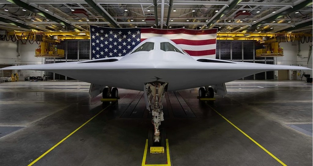
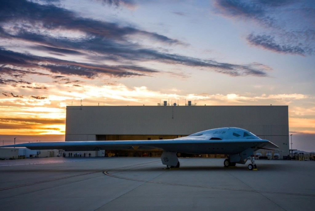
B-21 in a hangar at Plant 42 in Palmdale, California
The Northrop Grumman B-21 Raider is an American strategic bomber under developed for the United States Air Force (USAF) by Northrop Grumman. As part of the Long Range Strike Bomber (LRS-B) program, it is a long-range, stealth intercontinental strategic bomber for the USAF, able to deliver conventional and thermonuclear weapons.
The classified Long Range Strike Bomber (LRS-B) program began in 2011, and the Air Force issued a request for proposal to develop a LRS-B aircraft in July 2014. A development contract was awarded to Northrop Grumman in October 2015. Boeing and Lockheed Martin, who submitted losing bids for the project, filed bid protests; in October 2016, the Government Accountability Office (GAO) rejected the challenges and sustained the USAF’s decision to award the LRS-B contract to Northrop Grumman. The GAO report revealed that cost was the deciding factor in selecting Northrop Grumman over the Boeing-Lockheed Martin team.
In March 2016, the USAF announced seven tier-one suppliers for the program: Pratt & Whitney, BAE Systems, Spirit AeroSystems, Orbital ATK, Rockwell Collins, GKN Aerospace, and Janicki Industries.
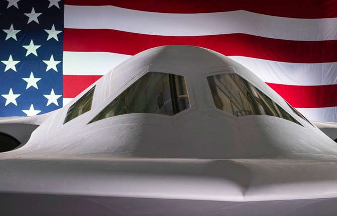
Many aspects of the B-21 program are highly classified; the program is designated as a special access program. The Congressional Research Service noted in a report that the B-21’s technical details and specifications, such as speed, enabling systems, “size, required stealth, structure, number and type of engines, projected weapons, and onboard sensors remain classified” although some information about various other aspects of the program have been made public since 2015. A 2015 media report said that the Air Force wanted the bomber to also function as an intelligence collection platform, battle manager, and interceptor aircraft. In 2016, then–Secretary of the Air Force Deborah Lee James said that the B-21 would be a “fifth-generation global precision attack platform” with networked sensor-shoot capability. Northrop Grumman described the B-21 at its 2022 “unveiling” as “the world’s first sixth-generation aircraft.”
The F-35 program manager Chris Bogdan said the B-21’s engines would be similar enough to the F-35’s Pratt & Whitney F135 engine to reduce its cost.
In January 2020, Air Force officials released new B-21 renderings and Northrop Grumman, showing the distinctive flush and blended inlets and the two-wheel main landing gear design. The drawing appeared to show a smaller, lighter aircraft than the B-2.
The program completed its critical design review in December 2018.
In September 2022, the USAF announced that the B-21 was to be unveiled in early December 2022 in Palmdale, California. The bomber was first shown to the public at a 2 December 2022 ceremony at Northrop Grumman’s production facilities in Palmdale, California. At the unveiling, Northrop CEO Kathy Warden said that the B-21 is designed with modular, open systems architecture to allow easy upgrades, and potentially, the ability to export components to foreign buyers. Warden said that the B-21’s internal operations were “extremely advanced compared to the B-2” and that the B-21 was slightly smaller than the B-2, with a longer range.
While the potential for an uncrewed flight was not mentioned during the ceremony, a US Air Force spokeswoman said the aircraft was “provisioned for the possibility, but there has been no decision to fly without a crew”.
At the 2016 Air Warfare Symposium, Air Force officials announced that the LRS-B would be formally designated “B-21” because the aircraft would be the 21st century’s first bomber. In September 2016, Air Force officials announced that the B-21 would be named “Raider” in honor of the Doolittle Raiders. The then-remaining survivor of the Doolittle Raiders, retired Lt. Col. Richard E. Cole, was present at the naming ceremony at the Air Force Association conference.
The head of the Air Force Global Strike Command said he expected the service would place an initial order for 100 B-21s and build up to a full fleet of 175 to 200. Two USAF studies suggested that Air Force could increase its initial purchase from 80-to-100 to 145 aircraft. Initial operating capability (IOC) was expected to be reached by 2030.
Assembly of the B-21 takes place at the United States Air Force Plant 42 near Palmdale, California, at the same facility Northrop Grumman used during the 1980s and 1990s to build B-2 bombers. In January 2017, Northrop Grumman was awarded a $35.8 million contract modification for a large coatings facility at Plant 42, to be completed by the end of 2019; the contract announcement did not specifically mention B-21, but the facility was likely meant for B-21 stealth coating. Because the program is classified, officials released very little information about it. By the summer of 2019 it was reported that construction of the first unit was underway. In early 2021, several media outlets reported that as completion of the first B-21 approached, construction on the second unit had begun.
By February 2022, six B-21s were under construction. The first B-21 was moved to a calibration facility the following month. About 5,000 Northrop Grumman employees worked on the program as of December 2022.
As of 2022, the B-21 was expected to enter service by 2026 or 2027. It is to complement and eventually replace the Northrop Grumman B-2 Spirit, but not the Boeing B-52 Stratofortress bombers.
In December 2022, the cost of a B-21 aircraft was estimated to be US$700 million; at the time, Air Force officials estimated that the cost to develop, purchase, and operate a fleet of 100 B-21s over a 30-year period would be at least $203 billion.
The first B-21 at Northrop’s Plant 42 in Palmdale, California, 29 November 2022.
Maintenance and sustainment of the B-21 will be coordinated by Tinker Air Force Base, Oklahoma, while Edwards Air Force Base, California, will lead testing and evaluation. In March 2019, Ellsworth was selected as the base to host the first operational B-21 unit and the first training unit.
In May 2022, the USAF announced that they expected first flight of the B-21 to take place in 2023.
The new bomber has stayed on cost and on schedule. The Air Force has set a $500 million ceiling for the unit cost in 2010 dollars; in 2019, Northrop said the Air Force’s target cost would be just over $600 million, accounting for inflation.
The first new B-21s will be based out of Ellsworth Air Force Base in South Dakota, and formal training will be conducted there as well. Maintenance and sustainment will be handled at Tinker Air Force Base in Oklahoma, while testing and evaluation is being performed at Edwards Air Force Base in California.
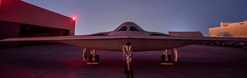
B-21, also known as Cerberus, achieved its first flight to Edwards Air Force Base on November 10, 2023.
The consortium of Northrop Grumman and its subsidiary, Scaled Composites, along with BAE Systems, was among the most favoured teams to win the competition to replace hundreds of T-38 Talon trainers for the USAF under the T-X program.
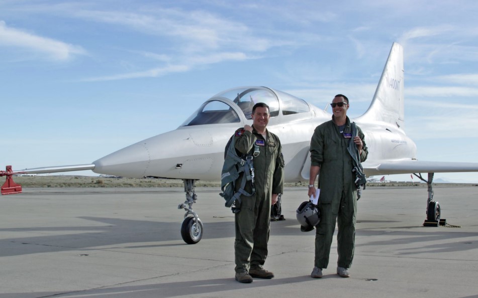
The Northrop Grumman and their teammates were progressing well with their T-X entrant, which received the in-house name Model 400. The jet was first spotted at Mojave Air And Space Port, where Scaled Composites calls home, in late August of 2016. The company made no comment on the prototype even as low quality photos of it taxiing hit the web. Not too long after it took to the skies, but still the only indication from Northrop Grumman that it existed was them stating that the Model 400 prototype would be officially unveiled in early 2017.
Originally, Northrop Grumman intended to run with an updated version of BAE System’s Hawk T2 trainer, but that idea was axed when it was clear that the 40-plus-year-old design would not meet the USAF’s performance requirements. Following this change in strategy, Northrop Grumman’s design process became especially secretive—although it was widely known that Scaled Composites, acquired by Northrop Grumman in 2007, would be heavily involved.
Dubbed the Model 400, the aircraft looks like a modernized, composite hybrid of the T-38 Talon and the F-20 Tigershark. It packs a single F404-GE-102D engine, a derivative of the same engine used in the F/A-18A/D, the JAS-39A/D (Volvo RM12), the F-117A, and India’s Tejas light fighter—as well as Lockheed’s T-X competitor, the T-50A.
The engine/airframe appears to lack an expanding nozzle usually indicative of an afterburning capability. Ultimately, this design can potentially be pitched as an entirely new aircraft while still leveraging Northrop’s hugely successful T-38 Talon lineage.
Just around the time that the company was supposed to officially unveil their exciting new T-X contender, one that had been flying for some time at that, the company canned its participation in the T-X program entirely. The move was startling to say the least, with Northrop Grumman not only giving up the possible opportunity to build at least 350 new tactical jets—an opportunity that is becoming increasingly rare—but also giving up on 50 plus years of pilot training heritage.
Model 400 test pilots. Note the rear main landing appear to be borrowed from the T-38
A statement by Northrop Grumman reads: “Northrop Grumman and its principal teammate BAE Systems have carefully examined the U.S. Air Force’s T-X Trainer requirements and acquisition strategy as stated in the final request for proposals issued on Dec. 30, 2016. The companies have decided not to submit a proposal for the T-X Trainer program, as it would not be in the best interest of the companies and their shareholders.”
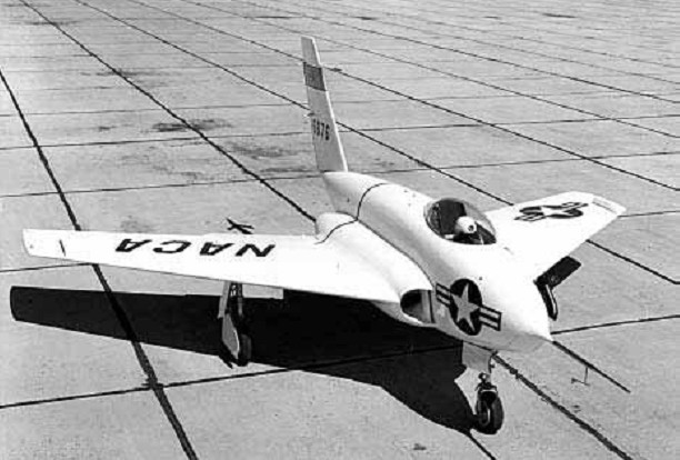
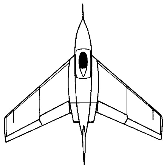
The Northrop X-4 was the first example of an X-vehicle intended to research something besides supersonic flight. The jet-powered X-4 was designed to evaluate the characteristics of a tailless aircraft at high subsonic speeds, a configuration believed to hold a great deal of promise for future aircraft.
The final Northrop flying wing design, although it could more accurately be described as a tailless aircraft, was the XS-4 Skylancer, a transonic research vehicle with two 726kg thrust Westinghouse turbojets. Later redesignated X-4, the first of two aircraft flew at Muroc on 16 December 1948, followed by the second on 7 June 1949.
Although not designed for supersonic speeds, the X-4 nevertheless proved that tailless swept-wing aircraft were not well suited for high transonic or supersonic performance. Pitch, roll, and yaw instabilities were very pronounced at speeds in excess of Mach 0.88, and there was no solution to the problem using the technology available at the time. The last flight was made on 29 September 1953. After a total of 102 flights, the highest achieved was 42,300 feet (approx) and fastest Mach 0.90 (630 mph) (approx).
Both aircraft survived the flight test program, and there were no serious accidents during the 102 flights. The first X-4 was on display at Edwards AFB. The second aircraft, after long being displayed at Maxwell AFB, Alabama, moved to the Air Force Museum in Dayton, Ohio.
X-4 Bantam Engines: 2 x Westinghouse turbojets, 726kg each Max take-off weight: 3175 kg / 7000 lb Wingspan: 8.18 m / 26 ft 10 in Length: 7.1 m / 23 ft 4 in Wing area: 19 sq.m / 204.51 sq ft Max. speed: 1000 km/h / 621 mph Crew: 1