The Pratt & Whitney Canada PW300 series is a family of turbofan engines developed by Pratt & Whitney Canada specifically for business jet applications.
The basic configuration of the PW300 is as follows: single stage fan, driven by a three-stage low pressure turbine, supercharging a four-stage axial/single stage centrifugal high pressure compressor, driven by a two stage high pressure turbine. An annular combustor is featured. Some versions have an unmixed exhaust, but the PW306 and PW308 include a forced mixer. A Full Authority Digital Engine Control (FADEC) system is incorporated.
The PW307A is a new centre-line engine developed specifically for a tri-jet application on the Dassault Falcon 7X. The PW307 was certified by Transport Canada in March 2005.
The PW308A has been chosen to power the Scaled Composites White Knight Two, the launch aircraft for Virgin Galactic’s SpaceShipTwo.
Variants: PW305A 20.81kN variant used on the Bombardier Learjet 60
PW305B 23.41kN variant used on the Hawker 1000
PW306A 25.36kN variant used on the IAI Galaxy & Gulfstream G200
PW306BL variant used on the Dornier 328JET
PW306C 25.67kN variant used on the Cessna Citation Sovereign
PW307A 28.49kN variant used on the Dassault Falcon 7X
PW307B variant used on the Bombardier Learjet 85
PW308A 30.69kN (6900 lb) variant used on the Hawker 4000 & Scaled Composites White Knight Two
PW308C 31.14kN variant used on the Dassault Falcon 2000EX/DX/LX
The Pratt & Whitney Canada PW100 aero engine family is a series of 2,000 to 5,000 horsepower (1,500 to 3,700 kW) turboprops manufactured by Pratt and Whitney’s Canadian subsidiary. The engine first entered service in 1984.
Originally called the PT7, the PW100 uses a relatively unusual three-shaft engine configuration. In the PW100, a centrifugal LP impeller (except for the PW150 which uses a 3-stage axial LP compressor), driven by a single stage LP turbine, supercharges a centrifugal HP impeller, driven by a single stage HP turbine. Power is delivered to the offset propeller reduction gearbox via a third shaft, connected to a 2-stage free (power) turbine.
Variants: PW115
PW118 Certified in 1986 with a maximum continuous rating of 1892eshp (1411kW), can be converted to a PW118A.
PW118A Certified in 1987 with a maximum continuous rating of 1893eshp (1412kW), can be converted to a PW118B.
PW118B Certified in 1996 with a maximum continuous rating of 1892eshp (1412kW).
PW119
PW119A Certified in 1992 with a maximum continuous rating of 1948eshp (1453kW), can be converted to a PW119B.
PW119B Certified in 1993 with a maximum continuous rating of 1941eshp (1448kW), can be converted to a PW119C.
PW119C Certified in 1995 with a maximum continuous rating of 1941eshp (1448kW), can be converted to a PW119B.
PW120 Certified in 1983 with a maximum continuous rating of 1787eshp (1333kW), can be converted to a PW121.
PW120A Certified in 1984 with a maximum continuous rating of 1892eshp (1411kW), can be converted to a PW121.
PW121 Certified in 1987 with a maximum continuous rating of 2044eshp (1524kW), can be converted to a PW120.
PW121A Certified in 1995 with a maximum continuous rating of 1992eshp (1465kW).
PW123 Certified in 1987 with a maximum continuous rating of 2261eshp (1687kW), can be converted to a PW123B, C, D or E.
PW123AF Certified in 1989 with a maximum continuous rating of 2261eshp (1686kW), can be converted to PW123.
PW123B Certified in 1991 with a maximum continuous rating of 2262eshp (1687kW), can be converted to a PW123.
PW123C Certified in 1994 with a maximum continuous rating of 2054eshp (1532kW), can be converted to a PW123 or D.
PW123D Certified in 1994 with a maximum continuous rating of 2054eshp (1532kW), can be converted to a PW123 or C.
PW123E Certified in 1995 with a maximum continuous rating of 2261eshp (1687kW), can be converted to a PW123.
PW124
PW124A
PW124B Certified in 1988 with a maximum continuous rating of 2522eshp (1881kW), can be converted to a PW123 or PW127.
PW125
PW125A
PW125B Certified in 1987 with a maximum continuous rating of 2261eshp (1687kW).
PW126 Certified in 1987 with a maximum continuous rating of 2323eshp (1732kW) can be converted to a PW123 or PW126A.
PW126A Certified in 1989 with a maximum continuous rating of 2493eshp (1859kW), can be converted to a PW123 or PW127D.
PW127 Certified in 1992 with a maximum continuous rating of 2619eshp (1953kW), can be converted to a PW127C,E or F.
PW127A Certified in 1992 with a maximum continuous rating of 2620eshp (1954kW), can be converted to a PW127B.
PW127B Certified in 1992 with a maximum continuous rating of 2619eshp (1953kW).
PW127C Certified in 1992 with a maximum continuous rating of 2880eshp (2148kW).
PW127D Certified in 1993 with a maximum continuous rating of 2880eshp (2148kW), can be converted to a PW127B.
PW127E Certified in 1994 with a maximum continuous rating of 2516eshp (1876kW), can be converted to a PW127M.
PW127F Certified in 1996 with a maximum continuous rating of 2619eshp (1953kW), can be converted to a PW127M.
PW127G Certified in 1997 with a maximum continuous rating of 3058eshp (2281kW).
PW127H Certified in 1998 with a maximum continuous rating of 2880eshp (2148kW).
PW127J Certified in 1999 with a maximum continuous rating of 2880eshp (2148kW).
PW127M Certified in 2007 with a maximum continuous rating of 2619eshp (1953kW).
PW150A Certified in 1998-06-24 with a maximum continuous rating of 5071 SHP (3782kW), although capable of up to 7000 SHP. Has a 3 stage axial low pressure compressor instead of the centrifugal NL unit on other variants. Used on the Bombardier Q400.
ST18M marine application for PW100
ST40M marine application for PW150A
Applications ATR 42 (PW120 on -200, PW127E on -500, PW127M on -600) ATR 72 (PW124B on -100 -200, PW127F or M on -500, PW127M on -600) BAe ATP (PW126) Bombardier 415 (PW123AF) Bombardier CL-215T (PW123AF) Bombardier Q100 (PW121) Bombardier Q200/Q300 (PW123) Bombardier Q400 (PW150) Canadair CL-415 (PW123AF) Dornier 328 (PW119) EADS CASA C-295 (PW127G) Embraer EMB 120 Brasilia (PW115, latterly PW118A) Euromil Mi-38 (PW127TS) Fokker 50 (PW125B) Fokker 60 (PW127B) Ilyushin Il-114 (PW127H) Xian MA60 (PW127J)
Specifications: Type: Turboprop Length: Diameter: Dry weight: 929 pounds Weight with accessories and fluid 1064 pounds Compressor: LP and HP independent centrifugal compressors. PW150 LP compressor is three-stage axial. Combustors: Annular reverse flow combustion chamber Turbine: Axial flow: single-stage HP; single-stage LP; the power turbine has two stages on all PW100 variants, and three stages on the PW150. Fuel type: JET A Oil system: Self-contained system Maximum power output: PW120 – takeoff 1800shp – Rto 2000shp PW121 – takeoff 1900shp – Rto 2100shp PW124 – takeoff 2160shp – Rto 2400shp PW127 – takeoff 2475shp – Rto 2750shp Turbine inlet temperature: max ITT for Reserve takeoff power, 816c Start 950c 5 seconds
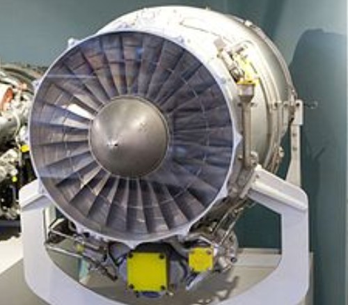
The Pratt & Whitney Canada JT15D is a small turbofan engine built by Pratt & Whitney Canada and first run in 1966. It was introduced in 1971 at 2,200 lbf (9,800 N) thrust, and has since undergone a series of upgrades to just over 3,000 lbf (13 kN) thrust in the latest versions. It is the primary powerplant for a wide variety of smaller jet aircraft, notably business jets. Over 6,000 JT15D’s have been delivered since the 1970s, with over 30 million hours of operation.
The JT15D is rare among modern turbofans in that it uses a centrifugal compressor as its main high-pressure system. This was a common feature of early jet engines, but was quickly replaced by axial compressors in most roles due to its large frontal size. In the turbofan role most of the jet thrust is generated by the cold air blown past the engine, and the internal “jet” portion is quite small. In this role the high single-stage compression of the centrifugal design has advantages, and the main reason most small turbofans don’t use them is that they are often developments of previous turbojet designs.
In the JT15D the fan blows about 70% of the air into the bypass duct, producing most of the overall thrust. On JT15D-4 models and above there is a small “booster” axial stage just behind the fan which is running at the same speed as the fan and directing the remaining 30% of the airflow into the engine core. This air is further compressed by the centrifugal stage, and burned in a reverse-flow annular combustor. The hot gases flow through a “high-pressure” turbine that drives the centrifugal stage, and then two more turbines driving the fan and booster.
The first model, the JT15D-1, was introduced to power the Cessna Citation I, then known as the Fanjet 500. Deliveries started in 1972, and eventually on 1,417 -1s were delivered. The JT15D-4 was introduced the next year, improving thrust to 2,500 lbf (11,000 N). The -4 was the primary engine for the Cessna Citation II, and went on to find use on the Mitsubishi Diamond 1A, Aerospatiale Corvette and SIAI Marchetti S.211. Eventually 2,195 engines of the -4 series were delivered.
The next major model was the JT15D-5, certified in 1983. The first versions delivered 2,900 lbf (13,000 N) and were used on the Beechjet 400A and Cessna T-47A. Several minor versions were introduced, the -5A for the Cessna Citation V, while the -5B powered the Beechcraft T-1A Jayhawk, the -5C the DASA Ranger 2000 and S-211A.
A more major upgrade was the JT15D-5D, which was certified in 1993. It increased thrust again, this time to 3,045 lbf (13,540 N). The -5D is used on the Cessna UC-35A and Cessna Citation Ultra. The D-5 of 2965 lb take-off rating was produced for the Diamond II/Beech 400A. The JT15D-5R is a later development, identical in all respects to the -5 except for changes to the fuel and oil systems associated with the elimination of the Fuel System Icing Inhibitor (FSII) additive.
Applications: Aérospatiale Corvette Alenia Aermacchi M-311 Beechcraft Beechjet 400 Cessna Citation I Cessna Citation II Cessna Citation V/Ultra Hawker 400 Mitsubishi MU-300 Diamond Raytheon T-1 Jayhawk Rockwell Ranger 2000 SIAI Marchetti S.211/Aermacchi S-211 Sport Jet II Boeing Bird of Prey
Specifications: JT15D-1 Takeoff thrust: 9,8 kN / 2200 lb Continuous thrust: 9,3 kN Length: 1506 mm Diameter: 691 mm Dry weight: 223,5 kg Bypass ratio: 3,3
JT15D-4 Takeoff thrust: 11,12 kN / 2500 lb Continuous thrust: 10,56 kN Length: 1600 mm Diameter: 686 mm Dry weight: 253 kg Bypass ratio: 2,6
JT15D-4C Takeoff thrust: 11,12 kN Continuous thrust: 10,56 kN Length: 1600 mm Diameter: 686 mm Dry weight: 261 kg Bypass ratio: 2,6
JT15D-5 Takeoff thrust: 12,92 kN Length: 1600 mm Dry weight: 287 kg Bypass ratio: 2
JT15D-5A Takeoff thrust: 12,92 kN Length: 1600 mm Dry weight: 287 kg Bypass ratio: 2
JT15D-5B Takeoff thrust: 12,92 kN Length: 1600 mm Dry weight: 292 kg Bypass ratio: 2
JT15D-5C Takeoff thrust: 14,21 kN Length: 1600 mm Dry weight: 302 kg Bypass ratio: 2
JT15D-5D Type: Turbofan Length: 60.5 in / 1531 mm Diameter: 27 inches Dry weight: 630 lb / 292,6 kg Compressor: Axial flow LP, centrifugal flow HP Fan Diameter: 520 mm Bypass ratio: 3,3 Maximum thrust: 3,050 pounds Takeoff thrust: 13,56 kN Specific fuel consumption: 0.562 at max, 0.552 at cruise (typ) Thrust-to-weight ratio: 4.58/1 (approximation)
JT15D-5F Takeoff thrust: 12,92 kN Length: 1600 mm Dry weight: 288 kg Bypass ratio: 2
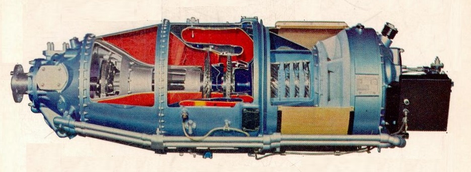
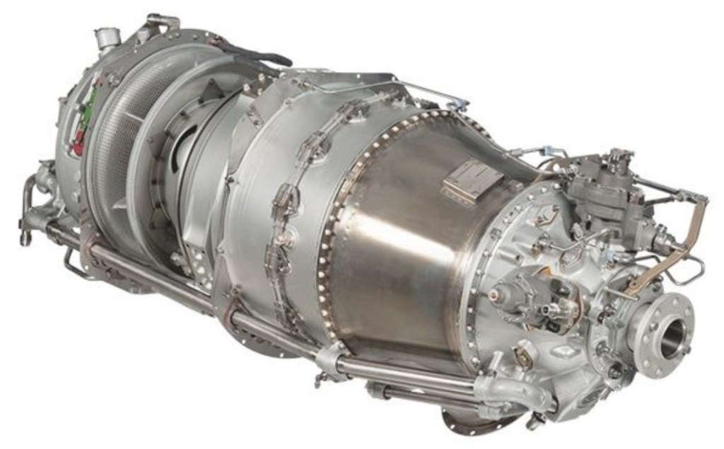
Development of the PT6 family started in the late 1950s, as a modern replacement for the Pratt & Whitney Wasp radial engines of that time. It first flew on 30 May 1961, mounted on a Beech 18 aircraft at de Havilland Canada’s Downsview, Ontario facility. Full-scale production started in 1963, entering service the next year.
The engine consists of two sections that can be easily separated for maintenance. In the gas-generator section air enters through an inlet screen into the low-pressure axial compressor. This has three stages on small and medium versions of the engine and four stages on large versions. The air then flows into a single-stage centrifugal compressor, through the annular reverse-flow combustion chamber, and finally through a single-stage compressor turbine that powers the compressors at about 45,000 rpm. The hot gas from the gas generator section then flows into a separate power section of the engine, containing a single-stage power turbine driving the power take-off system at about 30,000 rpm. For turboprop use, this powers a two-stage planetary output reduction gearbox, which turns the propeller at a speed of 1,900 to 2,200 rpm. The exhaust gas then escapes through two side mounted ducts in the power turbine housing, and is directed away from the engine in order to provide up to 600 lbf (2,700 N) of jet thrust. The engine is arranged such that the power turbines are mounted inside the combustion chamber, reducing overall length.
In most aircraft installations the PT6 is mounted backwards in the nacelle, so that the intake side of the engine is facing the rear of the aircraft. This places the power section at the front of the nacelle, where it can drive the propeller directly without the need for a long shaft. Intake air is usually fed to the engine via an underside mounted duct, and the two exhaust outlets are directed rearward. This arrangement also aids maintenance by allowing the entire power section to be removed along with the propeller, exposing the gas-generator section.
In US military use, they are designated as T74 or T101.
The PT6A large added an additional power turbine stage and a deeper output reduction, producing almost twice the power output, between 1,090 and 1,920 shp (1,430 kW).
The PT6A-67A is equipped with an epicyclic speed reduction gear box to minimise the propeller noise by optimising the output speed. It also houses a single-stage centrifugal compressor, multistage axial, reverse flow combustor and a single-stage compressor turbine.
PT6A-20
The PT6B is a helicopter turboshaft model, featuring an offset reduction gearbox with a freewheeling clutch and power turbine governor, producing 1,000 hp (750 kW) at 4,500 rpm.
The PT6C is a helicopter model, with a single side-mounted exhaust, producing 2,000 hp (1,500 kW) at 30,000 rpm, which is stepped down in a user-supplied gearbox.
The PT6T Twin-Pac consists of two PT6 engines driving a common output reduction gearbox, producing almost 2,000 hp (1,500 kW) at 6,000 rpm. The ST6 is a version intended for stationary applications, originally developed for the UAC TurboTrain, and now widely used as auxiliary power units on large aircraft, as well as many other roles.
When de Havilland Canada asked for a much larger engine, roughly twice the power of the PT6 Large, Pratt & Whitney Canada responded with a new design initially known as the PT7. During development this was renamed to become the Pratt & Whitney Canada PW100.
By the 40th anniversary of its maiden flight in 2001, over 36,000 PT6As had been delivered, not including the other versions. The engine is used in over 100 different applications.
The PT6A Dash 66D engine in the 850 has four stages of axial compressors plus a final stage of centrifugal compression. The pressure is increased by each stage of the process. When the engine is operating at cruise power, only a small portion of the compressed air must be bled to maintain the 6.2 psi cabin pressure and keep the TBM 850 cabin pumped up. But, the rules require that the cabin pressure must be maintained when the engine power is low. In other words, you must be able to chop the power at the certified ceiling without the cabin altitude climbing. To meet that requirement, the TBM 700 tapped bleed air from a higher pressure section of the compressor than was needed for normal cruise and descent and that used more engine power. The new 850 has two engine-bleed taps to satisfy normal cruise power pressurization and the low power high-altitude condition.
Variants:
PT6A The PT6A family is a series of free turbine turboprop engine providing 500 to 1,940 shp (433 to 1,447 kW).
PT6A-15AG optimised for agricultural aircraft 715 eshp and 680 shp
PT6A-20 579 eshp and 550 shp
PT6A-21 580 eshp and 550 shp
PT6A-25 580 eshp and 550 shp (-25, -25A) 783 eshp and 750 shp (-25C)
PT6A-27 715 eshp and 680 shp
PT6A-28 715 eshp and 680 shp
PT6A-29 778 eshp and 750 shp
PT6A-34 783 eshp and 750 shp
PT6A-35 787 eshp and 750 shp
PT6A-36 783 eshp and 750 shp
PT6A-38 801 eshp and 750 shp
PT6A-40 749 eshp and 700 shp
PT6A-41 903 eshp and 850 shp
PT6A-42 903 eshp and 850 shp
PT6A-45 1070 eshp and 1020 shp
PT6A-50 1022 eshp and 973 shp
PT6A-52 898 eshp and 850 shp
PT6A-60 1113 eshp and 1050 shp (-60, -60A) 1081 ehsp and 1020 shp (-60AG)
PT6A-61 902 eshp and 850 shp
PT6A-62 1218 eshp and 950 shp
PT6A-64 747 eshp and 700 shp
PT6A-65 1249 eshp and 1173 shp (-65B, -65R) 1298 eshp and 1220 shp (-65AG, -65AR)
PT6A-66 905 eshp and 850 shp (-66, -66A, -66D) 1010 eshp and 950 shp (-66B)
PT6A-67 1272 eshp and 1200 shp (-67, -67A, -67B, -67P) 1285 eshp and 1214 shp (-67D) 1294 eshp and 1220 shp (-67AF, -67AG, -67R, -67T) 1796 eshp and 1700 shp (-67F)
PT6A-68 1324 eshp and 1250 shp
PT6A-110 502 eshp and 475 shp
PT6A-112 528 eshp and 500 shp
PT6A-114 632 eshp and 600 shp (-114) 725 eshp and 675 shp (-114A)
PT6A-116 736 eshp and 700 shp
PT6A-121 647 eshp and 615 shp
PT6A-135 787 eshp and 750 shp
T74 United States military designation for the PT6A-20/27, used in the Beechcraft U-21.
T101 United States military designation for the T101-CP-100 / PT6A-45R, used in the Shorts 330 and Shorts C-23 Sherpa.
PT6B-9 550 hp (410.1 kW) turbo-shaft engine for use in helicopters. A later mark of PT6B is rated at 981 hp (731.5 kW).
PT6C 1600 to 2300 horsepower (1190 to 1720 kW) engine for helicopters and tiltrotors.
PT6D-114A Based on the PT6A-114A. The main difference is the deletion of the second stage reduction gearing and output shaft, because the engine is intended for integration with a combining gearbox incorporating power turbine governors and a propeller output shaft.
PT6T Twin PT6 power units combining outputs through a gearbox for use in helicopters.
ST6 Variant originally developed as a powerplant for the UAC TurboTrain power cars, but later developed as a stationary power generator and auxiliary power unit.
ST6B 550 bhp (410 kW) version of the PT6 developed for use in the STP-Paxton Turbocar, raced in the 1967 Indianapolis 500.
STN 6/76 500 bhp (370 kW) version of the PT6 developed for use in the Lotus 56, raced in the 1968 Indianapolis 500 and later in Formula One races, in 1971.
Applications:
PT6A AASI Jetcruzer Aero Ae 270 Ibis Air Tractor AT-400 Air Tractor AT-501 Air Tractor AT-602 Air Tractor AT-802 Antilles Super Goose Antonov An-28 Ayres Turbo Thrush Basler BT-67 Beechcraft 1900 Beechcraft Model 99 Beechcraft C-12 Huron Beechcraft King Air Beechcraft Lightning Beechcraft Model 87 Beechcraft Model 99 Beechcraft RC-12 Guardrail Beechcraft RU-21C Ute Beechcraft Starship Beechcraft Super King Air Beechcraft T-6 Texan II Beechcraft T-34C Turbo-Mentor Beechcraft T-44 Pegasus Beriev Be-30K CASA C-212 series 300P Cessna 208 Caravan Cessna 425 Corsair/Conquest I Conair Turbo Firecat Conroy Tri-Turbo-Three de Havilland Canada DHC-2 Mk. III Turbo Beaver de Havilland Canada DHC-6 Twin Otter de Havilland Canada Dash 7 Dominion UV-23 Scout Dornier Do 128 Turbo Skyservant Dornier Seawings Seastar Epic LT Dynasty Embraer EMB 110 Bandeirante Embraer EMB 121 Xingu Embraer EMB 312 Tucano Embraer EMB 314 Super Tucano Frakes Mohawk 298 Frakes Turbocat Gulfstream American Hustler 400 Harbin Y-12 Helio AU-24 Stallion IAI Arava IAI Eitan JetPROP DLX Kestrel JP10 KAI KT-1 Let L-410 Turbolet Lancair Evolution NAL Saras NDN Fieldmaster FTS Turbo Firecracker PAC 750XL PAC Cresco Piaggio P.180 Avanti Pilatus PC-6/B Turbo-Porter Pilatus PC-7 Pilatus PC-9 Pilatus PC-12 Pilatus PC-21 Piper PA-31T Cheyenne Piper PA-42 Cheyenne III Piper PA-46-500TP Meridian Piper T1040 PZL-130T Turbo Orlik and PZL-130TC-II Orlik PZL M28 Skytruck Quest Kodiak Reims-Cessna F406 Caravan II Saunders ST-27/ST-28 Scaled Composites ATTT Shorts 330 Shorts 360 Short C-23 Sherpa Socata TBM Spectrum SA-550 Swearingen SA26-T Merlin IIA TAI Hürkuş US Aircraft A-67 Dragon
PT6A-6 Type: Turboprop Length: 62 in (1,575 mm) Diameter: 19 in (483 mm) Dry weight: 270 lb (122.47 kg) ComponentsCompressor: 3-stage axial + 1-stage centrifugal flow compressor Combustors: Annular reverse-flow with 14 Simplex burners Turbine: 1-stage gas generator power turbine + 1-stage free power turbine Fuel type: Aviation kerosene to MIL-F-5624E / JP-4 / JP-5 Oil system: Split system with gear type pressure and scavenge pumps, with pressure to gearbox boosted by a second pump. Maximum power output: 578 hp (431 kW) equivalent power at 2,200 output rpm for take-off Overall pressure ratio: 6.3:1 Specific fuel consumption: 0.67 lb/hp/hr (0.408 kg/kW/hr) Power-to-weight ratio: 2.14 hp/lb (3.52 kW/kg)
PT6A-11AG Diameter: 483 mm Length: 1.58 m Power: 550 kW (748 PS)
PT6A-50 Diameter: 483 mm Length: 1.73 m Dry weight: 193 kg Power: 705 kW (958 PS) Specific fuel consumption: 353 g/ekWh
PT6A-68C Diameter: 483 mm Length: 1.83 m Power: 1175 kW (1600 PS)
PT6B-36A Diameter: 825 mm Length: 1.5 m Dry weight: 169 kg Power: 732 kW (995 PS) Specific fuel consumption: 0.581 lbs/shph
PT6B-37A Diameter: 495 mm Length: 1.63 m Dry weight: 172 kg Power: 747 kW (1015 PS) Specific fuel consumption: 0.584 lbs/shph
PT6A-67A Length: 1.87m Diameter: 0.48m
PT6C-67B Diameter: 584 mm Length: 1.50 m Power: 895 kW (1217 PS)
PT6C-67C Diameter: 584 mm Length: 1.50 m Power: 1252 kW (1702 PS)
PT6C-67E Diameter: 584 mm Length: 1.50 m Dry weight: Power: 1324 kW (1800 PS) Specific fuel consumption:
PT6T-6B Diameter: 825 × 1105 mm Length: 1.67 m Dry weight: Power: 1469 kW (2000 PS) Specific fuel consumption: 0,602 lbs/shph
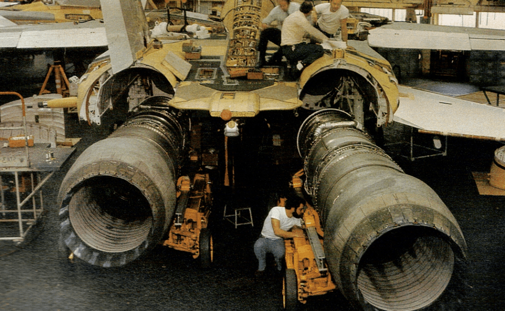
The Pratt & Whitney TF30 (company designation JTF10A) was a military low-bypass turbofan engine originally designed by Pratt & Whitney for the subsonic F6D Missileer missile carrier, but this project was cancelled. It was later adapted with an afterburner for supersonic designs, and in this form it was the world’s first production afterburning turbofan, going on to power the F-111 and the F-14A Tomcat, as well seeing use in early versions of the A-7 Corsair II without an afterburner. First flight of the TF30 was in 1964 and production continued until 1986.
In the 1958, the Douglas Aircraft Company proposed a short-range, four-engined jet airliner to fill the gap below its new DC-8 intercontinental; it was known internally as the Model 2067, and to be marketed as a four engine DC-9 which was later developed in a scaled down 2 engine DC-9 using the same engines due to emerging market demands. Pratt & Whitney (P&W) had offered its JT8A turbojet for the airliner, but Douglas preferred to go with a turbofan engine, which would have a greater fuel efficiency than a turbojet. P&W then proposed the JT10A, a half-scale version of its newly developed JT8D turbofan. Development of the new design began in April 1959, using the core of the JT8. Douglas shelved the model 2067 design in 1960, as the targeted US airlines preferred the newly offered Boeing 727.
In 1960, the United States Navy selected the JT10A, designated TF30-P-1, to power the proposed Douglas F6D Missileer, but the projected was canceled in April 1961. Meanwhile, the TF30 had been chosen by General Dynamics for its entrant in the TFX competition for the United States Air Force and USN, which was selected for production as the F-111. The version of the TF30 for the F-111 included an afterburner.
F-14 Pratt & Whitney TF30-P-412 turbofans
Operational history F-111 The F-111A/E used the TF30-P-103 (aka P-3) turbofan. The F-111 had problems with inlet compatibility, and many faulted the placement of the intakes behind the disturbed air of the wing. Newer F-111 variants incorporated improved intake designs and most variants featured more powerful versions of the TF30 engine. The F-111E used TF30-P-3 engines, the F-111D included TF30-P-9, and the F-111F had the TF30-P-100.
A-7 In 1964, the subsonic LTV A-7A Corsair II won the US Navy’s VAL competition for a light attack aircraft to replace the Douglas A-4 Skyhawk. The A-7A used a non-afterburning variant of the TF30, which would also power the improved A-7B and A-7C. In 1965, the USAF selected the A-7D as a replacement for its fast-jet F-100 and F-105 supersonic fighter-bombers. Though the USAF had wanted the TF30, Pratt & Whitney was unable to meet the production timetable because its facilities were already committed to producing other engines. Instead of producing the TF30 under license for P&W, the Allison Engine Company offered its own TF41 turbofan, a license-built version of the RB.168-25R Spey, to the AIr Force. The more powerful TF41 was selected by the USAF for the A-7D, and by the USN for its similar A-7E.
F-14 The Grumman F-14 Tomcat with the TF30 was underpowered, because it was the Navy’s intent to procure a jet fighter with a thrust-to-weight ratio (in clean configuration) of unity or better (the US Air Force had the same goals for the F-15 Eagle and F-16 Fighting Falcon). The F-14A’s thrust-to-weight ratio was similar to the F-4 Phantom II; however the new fuselage and wing design provided greater lift and a better climb profile than the F-4. The TF30 was found to be ill-adapted to the demands of air combat, and was prone to compressor stalls at high angle of attack if the throttles were moved aggressively. Because of the Tomcats’ widely spaced engine nacelles, compressor stalls at high AOA were especially dangerous because they tended to produce asymmetric thrust that could send the Tomcat into an upright or inverted spin, from which recovery was very difficult.
The F-14’s problems did not afflict TF30 engines in the F-111 to nearly the same extent, because that airplane was used as a strike aircraft. This type of mission is characterized by discrete phases so less abrupt changes in throttle, angle of attack and altitude are required. Though the F-14A entered service with the Navy powered by Pratt & Whitney TF30, by the end of the decade, following numerous problems with the original engine, the Department of Defense began procuring F110-GE-400 engines and installed them in the F-14A Plus (later redesignated to F-14B in 1991), which entered service with the fleet in 1988. These engines solved the reliability problems and provided nearly 30% more thrust, achieving a 1:1 dry thrust to weight ratio. The F-14D also used F110-GE-400 engines.
Variants: JTF10 – Company designation for the TF30 family of engines XTF30-P-1 YTF30-P-1 TF30-P-1 TF30-P-1A TF30-P-2 TF30-P-3 TF30-P-5 TF30-P-6 TF30-P-6A TF30-P-6C TF30-P-7 TF30-P-8 TF30-P-9 TF30-P-12 TF30-P-14 TF30-P-16 TF30-P-18 YTF30-P-100 TF30-P-100 TF30-P-408 JTF10A-7 – (TF30-P-2) JTF10A-10 SNECMA / Pratt & Whitney TF106 – A derivative of the TF30 to power the Dassault Mirage III-V VTOL fighter. SNECMA / Pratt & Whitney TF306 – A derivative of the TF30 to power the Dassault ‘Mirage’ IIIV 02 and tested in the Dassault Mirage F2.
Applications: Dassault Mirage F2 Dassault Mirage G2 General Dynamics F-111 General Dynamics F-111C General Dynamics/Grumman EF-111A Raven General Dynamics/Grumman F-111B General Dynamics F-111K Grumman F-14A Tomcat LTV A-7A/B/C Corsair II
Specifications: TF30-P-100 Type: Turbofan Length: 241.7 in. (6.139 m) Diameter: 48.9 in. (1.24 m) Dry weight: 3,985 lb. (1807 kg) Compressor: 2 spool axial: 3 fan and 6 low pressure stages, 7 high pressure stages Combustors: annular Turbine: 3 stage low pressure turbine, 1 stage high pressure turbine Maximum thrust: 14,560 lbf (64.766kN), 25,100 lbf (111.65kN) w/ afterburning Overall pressure ratio: 19.8 Bypass ratio: 0.878:1 Turbine inlet temperature: 2150F (1176C) Thrust-to-weight ratio: 6.0
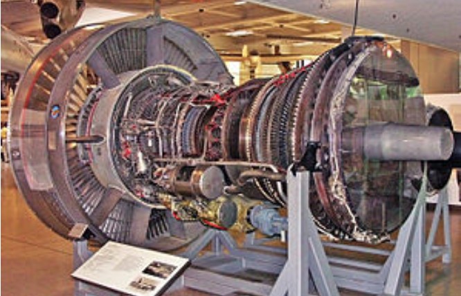
The Pratt & Whitney J58 (company designation JT11D) was a jet engine used on the Lockheed A-12, and subsequently on the YF-12 and SR-71 aircraft. The J58 was a single-spool turbojet engine with an afterburner.
The J58 was initially developed for the US Navy to power the planned version of the Martin P6M jet flying boat. Upon cancellation of this aircraft, it was selected by Convair and Lockheed for their supersonic projects. Other sources link its origin to the USAF’s requirement for a powerplant for the WS-110A, the future XB-70 Valkyrie. The J-58 produced 32,000 lbf (142 kN) of thrust. It was the first engine to be able to operate on afterburner for extended periods of time, and the first engine to be flight-qualified by the United States Air Force for Mach 3. A major feature of the J58 installation were the conical spikes in the variable-geometry inlets, which automatically moved fore and aft, controlled by an Air Inlet Computer. The spike altered the flow of supersonic air, ensuring good pressure recovery and minimum distortion at the engine inlet. The conical spikes are locked in the forward position below 30,000 feet and un-locked above that altitude. Above Mach 1.6 they are retracted approximately 1⅝ inch (4 cm) per Mach 0.1, up to total of about 26 inches (66 cm).
A variety of engine starting operations were available throughout the life of the A-12, F-12 and SR-71 aircraft, including: A twin chamber mono-fuel starter, attached to the engine only for starting, an AG330 starter cart, with two Buick Wildcat V8 internal combustion engines driving a common output, spinning the J58 to 3,200 rpm before the turbojet could self-sustain.
The engine’s high operating speeds and temperatures required a new jet fuel, JP-7. Its reluctance to be ignited required triethylborane (TEB) to be injected into the engine to ignite it, and to ignite the afterburner in flight; above -5 °C TEB spontaneously ignites in contact with air. Each engine carried a nitrogen-pressurized sealed tank with 600 cm3 (20.7 ounces) of TEB, sufficient for at least 16 starts, restarts, or afterburner lights; this number was one of the limiting factors of SR-71 endurance, as after each air refueling the afterburners had to be reignited. When the pilot moved the throttle from cut-off to idle position, fuel flowed into the engine, and shortly afterwards an approx. 50 cm3 (1.7 ounce) shot of TEB was injected into the combustion chamber, where it spontaneously ignited and lit the fuel with a green flash. In some conditions, however, the TEB flow was obstructed by coking deposits on the injector nozzle, hindering restart attempts. Refilling the TEB tank was a perilous task; the maintenance crew wore silver fire suits. Conversely, the JP-7 fueling was so safe that some aircraft maintenance was permitted during filling. The chemical ignition was chosen instead of a conventional igniter for reliability reasons, and to reduce mechanical complexity. The TEB tank is cooled with fuel flowing around it, and contains a disk that ruptures in case of overpressure, allowing TEB and nitrogen to discharge into the afterburner.
The fuel flowing into the engine is used as a coolant to cool the engine, hydraulic fluid, oil, TEB tank, afterburner nozzle actuator control lines, air conditioning systems, and the parts of the airframe subjected to aerodynamic heating.
The engine lubricant was a silicone-based grease. It was solid at room temperature, and was preheated prior to engine start.
Jet engines take in their air at about Mach 0.4 irrespective of their flight speed, whether it be zero or Mach 3. Efficient operation of the engine inlet requires that it delivers the air to the engine at that speed. The Lockheed Blackbird family of aircraft was designed to travel at speeds over Mach 3.2 and the slowing down of the air from this high speed to about Mach 0.4 was controlled by the intake shock cone and the shape of the downstream internal ducting(both were part of the airframe and designed by Lockheed). As air slows down, its temperature rises (to nearly 400 deg C at a flight speed of Mach 3.2) and it was this high temperature entering the compressor that prevented the J58, as originally designed, from powering the Blackbirds to Mach 3.2. This section describes how the compressor was modified for Mach 3.2 flight to handle the aerodynamic effects of high inlet temperature. The section is based on information in U.S.Patent 3,344,606 and the SR-71 Flight Manual.
The patent summarizes why the J58 would not work at Mach 3.2 – “As a result of the ram air temperature rise the thrust output drops because of insufficient airflow, compressor tolerance to surge (or compressor stall) is poor, and low compressor efficiency occurs resulting in high fuel consumption. Also the compressor blades are subjected to high stress from the combination of high rotational speed and flutter from rotating stall in the front stages”.
It specifies the object of the invention – “to improve the thrust generating quality of a turbojet engine with afterburner during high supersonic flight speed operation and to improve the compressor efficiency, the compressor surge margin and the compressor blade and vane fatigue problem”.
It summarizes the solution – “.. by bleeding a portion of the compressor air from an intermediate compressor stage and recovering the air in the afterburner for reheating therein prior to discharge to atmosphere with the remainder of the exhaust gasses”.
It was found that 20% of the engine flow needed to be bled from the fourth stage to combat the effects of high compressor inlet temperature and to restore the operation of the compressor to an acceptably high efficiency and flow capacity when operating at Mach 3.2.
The bleed air was returned to the engine to provide both cooling for the afterburner liner and more air for afterburner combustion. It passed through six external tubes from the compressor to the afterburner.
The SR-71 Flight Manual provides information on the use of the bleed (“bleed and IGV shift schedule”) in terms of engine RPM and Mach number or compressor inlet temperature. It shows that this air bleed, which it calls internal, is also necessary, together with an extra bleed, which it calls external, during starting and low engine RPM.
The schedule shows that variable inlet guide vanes (IGV) were also part of the compressor design. Unlike most variable IGV, where the whole vane pivots, the J58 vanes had 2-position, part-span trailing edge flaps only.
Like the bleed flow the position of the flaps was also determined by the engine speed and compressor inlet temperature.
A schematic view of the engine is also shown on the schedule showing the engine bleed air path from the compressor to the afterburner.
The final configuration of the J58 for Mach 3.2 flight was that of a “turbojet with bleed air recovery”, as stated in the patent. An alternative classification was a “turbojet with afterburner and compressor bleed bypass at high Mach”, as stated in the Flight Manual. The engine designation was JT11-D20.
The propulsion system consisted of the intake, engine, nacelle or secondary airflow and ejector nozzle(propelling nozzle). The propulsive thrust distribution between these components changed with flight speed. at Mach 2.2 inlet 13% – engine 73% – ejector 14% at Mach 3.0+ inlet 54% – engine 17.6% – ejector 28.4%
The intake had to supply air to the engine with minimum pressure loss and distortion and at the speed dictated by the engine, namely about Mach 0.4. It had to do this at all flight conditions.
The ejector nozzle, together with the engine variable nozzle, performed the reverse function of the inlet accelerating the turbine exhaust from about Mach 0.4 back up to Mach 3. Mach 3 exhaust velocity is higher than Mach 3 flight velocity due to the much higher temperature in the exhaust. The nacelle airflow from the intake controlled the expansion of the hot engine exhaust in the ejector nozzle. This air flowed around the engine and served also to cool the hot external parts of the engine and to purge any combustible mixtures in the event of a fuel or oil leak in the nacelle.
The Pratt & Whitney PW2000, also known by the military designation F117, is a series of high-bypass turbofan aero engines with a thrust range from 37,000 to 43,000 lbf (165 to 190 kN). Built by Pratt & Whitney, they were designed for the Boeing 757. As a 757 powerplant, these engines compete with the Rolls-Royce RB211.
The PW2000 is a dual-spool, axial air flow, annular combustion, high by-pass turbofan with a dual-channel Full authority digital engine control (FADEC) system. It was certified in 1984 as the first civilian FADEC-controlled aviation engine.
MTU Aero Engines holds a 21.2% stake in the engine, having developed the low-pressure turbine and turbine exit casing as well as producing critical parts of the low-pressure turbine, the turbine exhaust casing, high-pressure compressor and high-pressure turbine components.
The first PW2000 series engine, the PW2037, powered the Boeing 757-200 and entered service with Delta Air Lines as the launch customer for the civil aviation version of the engine.
Other than the 757, the PW2000 series engines also power the C-17 Globemaster III military transport; the United States Department of Defense designation for the engine is F117, with the specific variant used on the C-17 being the F117-PW-100. The powerplant first flew on the C-17 in 1991.
The PW2000 also powered the abortive Ilyushin Il-96M; the engine first flew on the Il-96M in 1993. On October 16, 2008 the NTSB recommended that the FAA issue urgent new inspection procedures on the PW2037 model of the engine, following an uncontained turbine failure event in August 2008. The NTSB recommended that the FAA order PW2037 engines inspected beyond a threshold of flight hours or flight cycles less than that of the event engine, and be reinspected at regular intervals.
A later build standard, named PW2043, launched in 1994. It provides over 43,000 lbf (190 kN) of thrust. Previous generations of engines can be converted to the PW2043 version.
Applications: Boeing 757 Boeing C-32 Ilyushin Il-96M C-17 Globemaster III
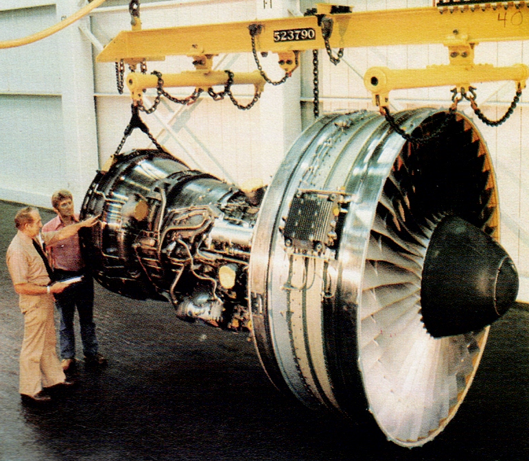
The JT9D was developed as part of the design phase of the C-5 Galaxy. A contract was awarded to Pratt & Whitney to study the type of large engine needed, but the production contract was eventually awarded to General Electric and their TF39 turbofan. First run in December 1966, the JT9D was chosen by Boeing to power the 747, with that aircraft’s first flight taking place on 9 February 1969. Flight testing of the engine had begun in June 1968, using a Boeing B-52E as a testbed.
The Pratt & Whitney JT9D engine was the first high bypass ratio jet engine to power a wide-body aircraft. Its initial application was the Boeing 747-100, the original “Jumbo Jet”. It was the company’s first high-bypass-ratio turbofan and also the first of today’s generation of large commercial turbofan engines to be produced.
The JT9D-3, which entered service in 1970, was constructed using titanium and nickel alloys. The engine featured a single stage fan, a three stage low pressure compressor and an eleven stage high pressure compressor coupled to a two stage high pressure turbine and four stage low pressure turbine. This version of the JT9D weighed 8,608 lb (3,905 kg) and produced 43,500 lbf (193,000 N) thrust. Production ceased in 1990.
JT9D-7R4
JT9D engines powering USAF E-4A airborne command posts are designated Pratt & Whitney F105. Pratt & Whitney’s designated successor to the JT9D family is the PW4000, which features fewer parts, greater reliability, and lower base selling price.
Applications: Airbus A300 Airbus A310 Boeing 747 Boeing 767 McDonnell Douglas DC-10
Specifications:
JT9D-3A Static Thrust: 45800 lbf Basic Engine Weight: 8608 lb Length: 128.2 in Fan Diameter: 92.3 in Used in: Boeing 747-100
JT9D-7 Static Thrust: 47900 lbf Basic Engine Weight: 8850 lb Length: 128.2 in Fan Diameter: 92.3 in Used in: Boeing 747
JT9D-20 Static Thrust: 49400 lbf Basic Engine Weight: 8450 lb Length: 128.2 in Fan Diameter: 92.3 in Used in: McDonnell Douglas DC-10, Boeing 747
JT9D-7Q/7Q3 Static Thrust: 53000 lbf Basic Engine Weight: 9295 lb Length: 132.1 in Fan Diameter: 93.6 in Used in: Boeing 747
JT9D-59A/70A Static Thrust: 53000 lbf Basic Engine Weight: 9155 lb Length: 132.2 in Fan Diameter: 93.6 in Used in: McDonnell Douglas DC-10/Boeing 747/Airbus A300
JT9D-7R4D/D1 Static Thrust: 48000 lbf Basic Engine Weight: 8905 lb Length: 132.7 in Fan Diameter: 93.4 in Used in: Boeing 767/Airbus A310
JT9D-7R4G2 Static Thrust: 54750 lbf Basic Engine Weight: 8935 lb Length: 132.7 in Fan Diameter: 93.4 in Used in: Boeing 747
JT9D-7R4H1 Static Thrust: 56000 lbf Basic Engine Weight: 8885 lb Length: 132.7 in Fan Diameter: 93.4 in Used in: Airbus A300
First run in 1960, the Pratt & Whitney JT8D is a low-bypass (0.96 to 1) turbofan engine, introduced by Pratt & Whitney in February 1963 with the inaugural flight of Boeing’s 727. It was a modification of the Pratt & Whitney J52 turbojet engine, which powered the US Navy A-6 Intruder attack aircraft. The Volvo RM8 is an afterburning version that was license-built in Sweden for the Saab 37 Viggen fighter. A “fixed” version for powerplant and ship propulsion is known as the FT12.
The JT8D is an axial-flow front turbofan engine incorporating dual-spool design. There are two coaxially-mounted independent rotating assemblies: one rotating assembly for the low pressure compressor (LPC) which consists of the first six stages (i.e. six pairs of rotating and stator blades, including the first two stages which are for the bypass turbofan), driven by the second (downstream) turbine (which consists of three stages); and a second rotating assembly for the high-pressure compressor (HPC) section, which has seven stages. The high-pressure compressor is driven by the first (upstream) turbine, which has a single stage.
The front-mounted bypass fan has two stages. The annular discharge duct for the bypass fan runs along the full length of the engine, so that both the fan air and exhaust gases can exit through the same nozzle. This arrangement allows some noise attenuation, in that the still-hot fast-moving turbine exhaust is shrouded in much-cooler and slower-moving air (from the bypass fan) before interacting with ambient air. Thus the JT8D noise levels were significantly reduced from previous non-turbofan engines, although the low bypass ratio meant that, compared to subsequently developed turbofans, high noise levels were still produced.
Eight models comprise the JT8D standard engine family, covering the thrust range from 12,250 to 17,400 pounds-force (62 to 77 kN) and power 727, 737-100/200, and DC-9 aircraft. More than 14,000 JT8D engines have been produced, totaling more than one-half billion hours of service with more than 350 operators making it the most popular of all low-bypass turbofan engines ever produced. Within the fan inlet case, there are anti-icing air bosses and probes to sense the inlet pressure and temperature. Similar units exist throughout the engine to check temperatures and pressures. At the 13th (i.e. the final) compressor stage, air is bled out and used for anti-icing. The amount is controlled by the Pressure Ratio Bleed Control sense signal (PRBC). The diffuser case at the aft end of the compressor houses the 13th stage. Its increasing cross-sectional area allows the compressed air to slow down before entering one of the engine’s nine burner cans. Again, there are two bosses to extract 13th stage air for anti-icing, de-icing of fuel, and airframe (cabin pressurization) use. Not all the compressed air enters the burner cans at the fuel-ignition point; some bypasses the can completely and cools the first turbine stage, and some is gradually introduced into the burner can’s perimeter in such a way that the burning fuel is held near the can’s centerline.
There are nine combustion chambers positioned in a can-annular arrangement. Each chamber has three air inlet hole sizes: the smallest is for cooling, the medium is for burning and the large for forming an air blanket.
In response to environmental concerns that began in the 1970s, the company began developing a new version of the engine, the JT8D-200 series. Designed to be quieter, cleaner, more efficient, yet more powerful than earlier models, the -200 Series power-plant was re-engineered with a significantly higher bypass ratio (1.74 to 1) covering the 18,500 to 21,700 pound-force (82 to 97 kN) thrust range and powering the McDonnell Douglas MD-80 series. This increase was achieved by increasing bypass fan diameter (from 39.9 to 49.2 inches) and reducing fan pressure ratio (from 2.21 to 1.92). Overall engine pressure ratio was also increased from 15.4 to 21.0. Since entering service in 1980, more than 2,900 of the -200 series engines have been produced.
The JT8D-217 and -219 engine(s) were tested in 2001 and were deemed suitable replacements for the old TF33 engines on military and commercial aircraft as part of the Super 27 re-engining program. The updated engines offer reduced (Stage-3) noise compliance standards without the need for hush kits, enhanced short field performance, steeper and faster climb rates with roughly a 10% reduction in fuel burn for extended range.
Pratt & Whitney, in a joint venture with Seven Q Seven (SQS) and Omega Air, has developed the JT8D-219 as a re-engine powerplant for Boeing 707-based aircraft. Northrop Grumman uses the -219 to re-engine the United States Air Force’s fleet of 19 Joint Surveillance Target Attack Radar System (E-8 Joint STARS) aircraft, which will allow the JSTARS more time on station due to the engine’s 17% greater fuel efficiency. NATO also plans to re-engine their fleet of E-3 Sentry AWACS aircraft. The -219 is publicized as being half the cost of the competing 707 re-engine powerplant, the CFM-56, for reasons of geometrical and balance similarity to the engine it is replacing and the associated relative up-front wing modification costs of the two choices.
Applications: Boeing 707RE Boeing 727 Boeing 737 Dassault Mercure McDonnell Douglas DC-9 McDonnell Douglas MD-80 series McDonnell Douglas YC-15 Northrop Grumman E-8C Joint STARS Sud Aviation Caravelle 10B, 10R, 11R, and 12 Kawasaki C-1( Japanese military transport) powered by the JT8D-M-9 manufactured by Mitsubishi
Accidents: 4 April 1977 Southern Airways Flight 242 – both engines on the DC-9 failed when the pilots flew into a severe thunderstorm after misreading their onboard radar. The flight encountered severe rain and hail. The NTSB concluded that the “loss of thrust was caused by the ingestion of massive amounts of water and hail which in combination with thrust lever movement induced severe stalling in and major damage to the engine compressors.” 63 people on-board and 9 on the ground died as a result of the accident.
22 August 1985 British Airtours Flight 28M – an engine failed during take-off from Manchester Airport, the fire spreading into the cabin, resulting in 55 fatalities aboard the Boeing 737-236 Advanced.
21 December 1991 Scandinavian Airlines Flight 751 – The engines on an MD-81 ingested wing ice during takeoff causing engine damage that led to a total loss of thrust on both engines. The aircraft crashed in a forest clearing with no fatalities.
6 July 1996 An engine explosion happened on an MD-88, Delta Air Lines Flight 1288, just prior to take-off at Pensacola, Florida, USA, with two fatalities.
5 September 2005 A Boeing 737-200 operated by Mandala Airlines crashed in Medan as Mandala Airlines Flight 091 with 96 passengers, five crew and 49 on the ground were killed. Sixteen passengers survived. The engine flamed out and lost power.
15 April 2008 A DC9-51 operated by Hewa Bora Airways crashed and burned at Goma following an engine fire, with 40 fatalities.
Specifications: JT8D-200 Type: Turbofan Length: 120.0″ / 3048mm – 154.1″ / 3914mm Diameter: 49.2″ / 1250mm Dry weight: From 3200lb / 1454.5kg (JT8D) to 4740lb / 2154.5kg (JT8D-219) Compressor: Axial flow, 2-stage fan, 6-stage LP, 7-stage HP Combustors: Nine can-annular combustion chambers Turbine: 3-stage (1 stage HP 2 stage LP) Maximum thrust: 21,700lbf / 96.5kN (JT8D-219) Overall pressure ratio: 16:1 Specific fuel consumption: 0.744 [kg/daN.h] Thrust-to-weight ratio: About 4.8
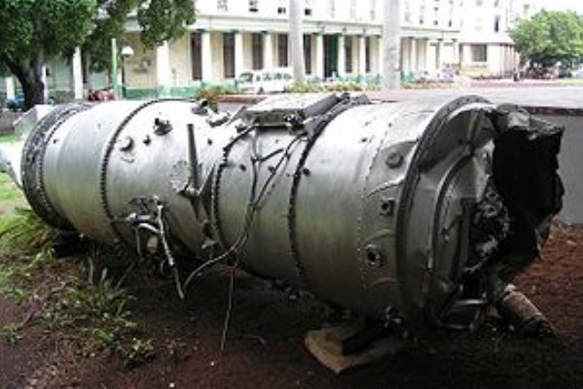
Part of a Pratt & Whitney J75 from a downed Lockheed U-2 in Cuba
The Pratt & Whitney J75 (company designation: JT4A) was an axial-flow turbojet engine first flown in 1955. A two-spool design in the 17,000 lbf (76 kN) thrust class, the J75 was essentially the bigger brother of the Pratt & Whitney J57 (JT3C). It was known in civilian service as the JT4A, and in a variety of stationary roles as the GG4 and FT4.
In military use, the J75 was used on the Lockheed U-2, the Republic F-105 Thunderchief, and the Convair F-106 Delta Dart. It was also utilized in the prototype and experimental Lockheed A-12, North American YF-107, Vought XF8U-3 Crusader III, Martin P6M SeaMaster, and Avro Canada CF-105 Arrow.
Before the arrival of the Pratt & Whitney JT3D turbofan engine, the JT4A was used to power certain Boeing 707 and Douglas DC-8 models, bringing improved field performance in the medium-range Boeing 707-220 and Douglas DC-8-20, and intercontinental range in the Boeing 707-320 and the Douglas DC-8-30.
After its relatively short lifetime in the aircraft role, the JT4A found more enduring use in the naval role, where the FT4 was produced in a variety of models between 18,000 and 22,000 hp. Well-known uses include the first all-turbine warships, the Canadian Iroquois class destroyers, as well as the United States Coast Guard’s Hamilton class cutters, and it was considered for the US Navy’s Asheville class gunboat. The same basic powerplant saw much wider use as a peak demand power turbine running on natural gas. From its introduction in 1960 over 1,000 FT4s have been sold, with many of them still in operation for electrical generation. Outdated by modern standards, refits were available that add catalytic converters to lower their emissions.