Rolls-Royce Avon / Svenska Flygmotor RM5 / RM6 / Westinghouse XJ54

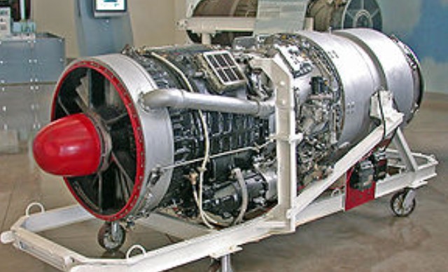
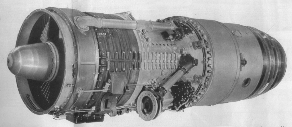
The Avon design team was headed by Cyril Lovesey, who had previously been in charge of Merlin development. The engine was intended both as an experiment in axial-flow turbojet engines, as well as (if successful) a replacement for the 5,000 lbf (22 kN) Nene. Originally known as the AJ.65 for Axial Jet, 6,500 lbf which was originally designed by Alan Arnold Griffith, the engine developed as a single-spool design with an eight, later 10 stage compressor, mass flow rate of 150 lb/s (68 kg/s) and a pressure ratio of 7.45. Development started in 1945 and the first prototypes were built in 1947.

The main series of the Avon were the 1 and 100 Series and the 200 Series. The I and 100 series have a similar axial flow compressor, while the 200 Series has a axial flow compressor with additional stages. In the 1 and 100 Series the combustion assembly consists of eight flame tubes in individual casings, but the 200 Series has flame tubes contained in an Annular casing.

The first bench testing of the Avon took place early in 1947. The first production version was running during 1949. In 1951, the first engines of the 100 and 200 Series were bench tested.

The take-off thrust of the Avon I was 6,500 lbs. Development of material allowed increased operating temperatures and when the 100 Series was introduced the thrust was 7,500 lb.

Introduction was somewhat slowed by a number of minor problems. The first Avons to fly were two Avon RA.2s in the converted Lancastrian military serial VM732, which flew from Hucknall on August 15, 1948. The prototype RA.2 weighed 2,400 lb and gave 6,000 lb thrust, while the production RA.3 was 125 lb lighter.

Initially a private venture for the company, government backing was forthcoming around the time of the first prototypes.

The engine eventually entered production in 1950, the original RA.3/Mk.101 version providing 6,500 lbf (29 kN) thrust in the English Electric Canberra B.2. Similar versions were used in the Canberra B.6, Hawker Hunter and Supermarine Swift.

The 200 Series began with 9,500 lb thrust and was soon 11,250 lb.

Uprated versions soon followed, the RA.7/Mk.114 in 1952, producing 7,350 lbf (32,700 N) in the de Havilland Comet C.2, the RA.14/Mk.201 of 9,500 lbf (42 kN) in the Vickers Valiant and the RA.26 of 10,000 lbf (44 kN) used in the Comet C.3 and Hawker Hunter F.6.

The first of the series with all-weather protection, the RA.7 had a power/weight ratio even better than that of the original production engines, notwithstanding the fact that it had been restressed to accept the loads imposed at transonic speeds. The RA.7R (the suffix “R” denotes that reheat, or afterburning, is fitted) delivers 9,500 lb static thrust at sea level, and an offshoot of the same family is the civil 500 Series, the 503 being the engine of the Comet 2.

Avon RA.14

The Avon RA.14 first ran in 1952. It has a longer compressor than its forerunners, and it also has a true annular combustion chamber in order to accept the tremendous mass flow without increasing “hoop” diameter. The R.A.14 was intended for installation in the wing (it is known that it powers the Vickers-Armstrongs Valiant B.1), and every effort has been made to reduce depth to a minimum.

Originally the Avon was made as a military engine but, in February 1952, the first flight in a civil aircraft was made. A civil counterpart is the RA.16 of 9,000 lb thrust, which was originally intended to power the Comet 3, though that aircraft had later variant, giving 10,000 lb thrust.

An Avon-powered de Havilland Comet 4 flew the first scheduled transatlantic jet service in 1958.

The modifications and improvements introduced to the Avon 200 series were considerable, resulting in a completely different engine with very little in common with the early Marks. Despite this, the name Avon was retained. Differences included a completely new combustion section, a 15 stage compressor based on that of the Armstrong-Siddeley Sapphire, as well as other improvements.

The line eventually topped out with the 12,690 lbf (56,450 N) and 16,360 lbf (72,770 N) in afterburner RA.29 Mk.301/2 (RB.146) used in later versions of the English Electric Lightning. Other aircraft to use the Avon included the de Havilland Sea Vixen, Supermarine Scimitar and Fairey Delta.

Avon RA29

The Avon was also produced under license by Svenska Flygmotor as the RA.3/Mk.109 as the RM5, and an uprated RA.29 as the RM6 with 17,110 lbf (76,110 N). The RM5 powered the Saab Lansen, while the RM6 was the main powerplant of the SAAB Draken.

Production was also carried out in Belgium by Fabrique Nationale, including 300 Avon 113s, and a larger number of Avon 203s.

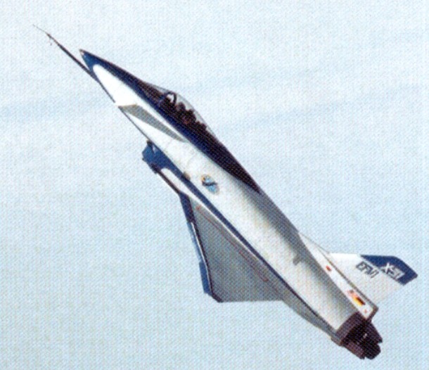
In the US, the Avon was used to power the vertical landing Ryan X-13 Vertijet aircraft (in RA.28-49 form).

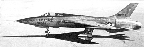
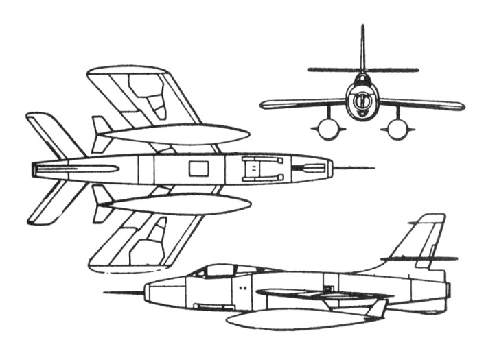
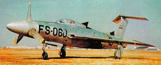
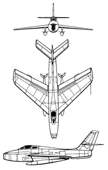
In Australia, the Avon was used by Commonwealth Aircraft Corporation to power its heavily modified variant of the F-86 Sabre, known as the CA-27 Avon-Sabre.

The Avon continued in aero engine production, mostly for the use in the Sud Aviation Caravelle and English Electric (BAC) Lightning, until 1974, by which time over 11,000 had been built. The engine garnered an impressive safety record over that time. The Avon remained in operational service with the RAF, powering the English Electric Canberra PR.9, until 23 June 2006.

The Avon 200 is an industrial gas generator that is rated at 21-22,000shp. As of 2011, 1,200 Industrial Avons have been sold, and the type has established a 60,000,000 hour class record for its class.

Variants:
AJ65
The original designation, standing for Axial Jet 6,500lbs thrust

RA.1
Prototype engines for testing and development.

RA.2
Pre-production engines for testing. 6,000 lbf (26.69 kN)

RA.3
Civil designation for the first Avon production mark – 6,500 lbf (28.91 kN).

RA.7
Civil designation for the uprated version of the Avon. – 7,350 lbf (32.69 kN).

Mk.114
Military designation for the RA.7 Avon – 7,350 lbf (32.69 kN)

RA.14
Civil designation for the uprated version of the Avon with can-annular combustion chamber and Sapphire style compressor – 9,500 lbf (42.26 kN).

RA.21
8,050 lbf (35.81 kN) Production engine developed from the RA.7.

RA.24

RA.26
Further improvements to the Avon 200 series

RA.28
Second generation variant 10,000 lbf (44.48 kN)

RA.29
Civil designation for the Mk.300 series (used by the Sud Aviation Caravelle)

RA.29/1

RA.29/3

RA.29/6

Mk.100 series
Military designation for the RA.3 Avon – 6,500 lbf (28.91 kN).

Mk.200 series
Military designation for the uprated version of the Avon with can-annular combustion chamber and Sapphire style compressor – 9,500 lbf (42.26 kN).

Mk.300 series
Developed after-burning engines for the English Electric Lightning.
RB.146 Mk.301:The ultimate Military Avon for the English Electric Lightning – 12,690 lbf (56.45 kN) dry, 16,360 lbf (72.77 kN) wet.

RB.146 Mk.302:Essntially similar to the Mk.301

Avon 504
Civilian equivalent to military Mk.200 variants.

Avon 506
Civilian equivalent to military Mk.200 variants.

Avon 522
Civilian equivalent to military Mk.200 variants.

Avon 524
Civilian equivalent to military Mk.200 variants.

Avon 524B
Civilian equivalent to military Mk.200 variants.

Avon 525
Civilian equivalent to military Mk.200 variants.

Avon 525B
Civilian equivalent to military Mk.200 variants.

Avon 527
Civilian equivalent to military Mk.200 variants.

Avon 527B
Civilian equivalent to military Mk.200 variants.

Avon 531
Civilian equivalent to military Mk.200 variants.

Avon 531B
Civilian equivalent to military Mk.200 variants.

Avon 532R
Civilian equivalent to military Mk.200 variants.

Avon 532R-B
Civilian equivalent to military Mk.200 variants.

Avon 533R
Civilian equivalent to military Mk.200 variants.

Avon 533R-11A
Civilian equivalent to military Mk.200 variants.

Svenska Flygmotor RM5
Licence production of the RA.3/Mk.109 for the Saab 32 Lansen

Svenska Flygmotor RM6
Uprated RA.29/Mk.300 for the Saab Draken

Westinghouse XJ54
Version of Avon intended to be produced/sold by Westinghouse in the US

Applications:
Military aviation:
CAC Sabre
de Havilland Sea Vixen
English Electric Canberra
English Electric Lightning
Fairey Delta 2
Hawker Hunter
Ryan X-13 Vertijet
Saab 35 Draken
Saab Lansen
Supermarine Swift
Supermarine Scimitar
Vickers Valiant

Civil aviation:
de Havilland Comet
Sud Aviation Caravelle

Other uses:
The Avon is also currently marketed as a compact, high reliability, stationary power source. As the AVON 1533, it has a maximum continuous output of 21,480 shp (16.02 MW) at 7,900 rpm and a thermal efficiency of 30%. In 1982, an Avon engine on gas pumping duty in a Canadian installation ran for 53,000 hours before requiring a major overhaul. In 1994, another industrial Avon engine ran non-stop for 476 days (11,424 hours).

As a compact electrical generator, the type EAS1 Avon based generator can generate a continuous output of 14.9 MW.
On 4 October 1983, Richard Noble’s Thrust2 vehicle, powered by a single Rolls-Royce Avon 302 jet engine, set a new land-speed record of 1,019.46 km/h (633.46 mph) at the Black Rock Desert in Nevada.

Specifications:
Avon 301R
Type: Turbojet
Length: 126 in (3,200 mm)
Diameter: 35.7 in (907 mm)
Dry weight: 2,890 lb (1,310 kg)
Compressor: 15-stage axial flow
Combustors: Cannular, 150 lb/s (68 kg/s)
Turbine: Two-stage axial flow
Fuel type: Kerosene
Maximum thrust: 12,690 lbf (56.4 kN)dry/16,360 lbf (72.8 kN) with reheat
Overall pressure ratio: 7.45:1
Specific fuel consumption: 0.932 lb/(lbf·h) or 26.4 g/(kN·s) (dry) 1.853 lb/(lbf·h) or 52.5 g/(kN·s) (wet)
Thrust-to-weight ratio: 5.66:1 (56 N/kg)

Rockwell- MBB X-31

The X 31 began as an Enhanced Fighter Manoeuvrability (EFM) demonstrator at NASA’s Dryden Flight Research Center at Edwards AFB. Designed to break the “stall barrier,” allowing it to flight at angles of attack which would typically cause an aircraft to stall with a complete loss of control, the X-31 employs thrust vectoring paddles that are located in the jet exhaust and small computer-controlled canards to help keep the aircraft stable at high attack angles. It incorporates an unusual delta wing design and three thrust vectoring paddles made of graphite epoxy and located on the aircraft’s aft fuselage. These direct the engine exhaust to provide control in pitch (up and down) and yaw (right and left) thereby increasing the aircraft’s manoeuvrability. In addition, the X 31 is configured with movable forward canards, wing control surfaces and fixed aft strakes. Coupled with advanced flight control systems, the result confers a significant advantage over conventional fighters in a close in combat situation.

The X 31 is the first co operative international X plane. At Dryden, the International Test Organization (ITO) expanded the flight test envelope. The ITO, managed by the Advanced Research Project Agency (ARPA), includes NASA, the US Navy, the US Air Force, Rockwell Aerospace, the Federal Republic of Germany and Deutsche Aerospace, formerly Messerschmitt Bolkow-Blohm.

To reduce costs, several parts of existing aircraft were used in the X 31. Canopy, ejection seat and control stick were taken from an F/A 18 while several parts of the landing gear and rudder are from an F 16. Brakes and wheels were provided by Cessna and are the same as those used on the Cessna Citation. Piloted by Rockwell chief test pilot Ken Dyson, the first aircraft, serial 164584, flew from Air Force Plant 42, Palmdale, Calif, on October 11, 1990. The second aircraft, 164585, made its first flight on January 19, 1991, with Deutsche Aerospace chief test pilot Dietrich Seeck at the controls. Powered by a single General Electric P404 GE 400 turbofan engine, known to be tolerant in disturbed air and capable to produce 16,000 lb of thrust with afterburner, the maximum speed achieved by the X 31 is Mach 1.28. Controlled flight at 70o angle of attack was accomplished at Dryden on November 6, 1992. On April 29, 1993, the X 31 successfully executed a rapid minimum radius, 180o turn using a post stall manoeuvre, flying well beyond the aerodynamic limits of any conventional aircraft. Later that summer, the first simulated dog-fights were performed against a NASA F/A-18 Hornet. This resulted in 63 victories for the X-31.

The first X-31 was lost in an accident on January 19, 1995, on its 292nd flight. Due to miscommunication between pilot and air traffic control and a missing pitot tube heating system the German pilot, Karl Heinz Lang, had to eject from his uncontrollable aircraft at 18,000ft. The aircraft crashed near Edwards AFB.

The second X-31 completed the 580th and last flight of its original research program on 13 May 1995 and was placed in storage.

In February 1998, the participating contractors started VECTOR Risk Reduction and Requirements Definition. The aircraft was shipped to NAS Patuxent River in April 2000, where it was largely rebuilt for the Vector (Vectoring Extremely Short Take-Off and Landing Control Tailless Operation Research) program.

VECTOR stands for Vectoring Extremely Short Take-Off and Landing Control and Tailless Operational Research and is being used to research extremely short take off and landing capabilities and also the aerodynamic characteristics of tailless flight using integrated thrust vector control. Three technology areas are involved:
Extremely Short Take Off and Landing (ESTOL) using thrust vectoring control

  • Flush Air Data System (FADS)
  • Tailless/reduced vertical tail configurations

This incorporated a new flight control software system was installed together with an auto throttle system, a belly mounted video camera and components of inertial navigation and global positioning systems. The revised aircraft made its first flight for Vector on 24 February 2001. After two months of basic flight testing, the aircraft began a year of upgrading and ground testing to perform ESTOL landings to a “virtual runway” at 5,000 feet. The X-31 took to the air again on 17 May 2002.

In these flights the aircraft flew thrust vectored, high precision ESTOL landings at reduced speeds and at high angles of attack.

To perform the automated approach, the pilot must fly into an invisible engagement box in the sky, then activate the ESTOL mode. Once successfully engaged, the pilot is not in control but is able to override the approach at any point. A video camera under the belly of the aircraft will allow the pilot to view the runway prior to landing because a pilot loses sight at anything above 15 degree angle of attack, so during final approach the aircraft will be controlled by autopilot. Coming in with its nose pointed high above the horizon, the first part of the aircraft to touch the runway would be the engine nozzle and not the landing gear. To prevent such an event, the X 31 performs [an automatic] derotation manoeuvre when the tail is just two feet above the runway, dropping onto its main landing gear. Timing of this manoeuvre is crucial; if the aircraft derotates early and drops too far, the landing gear could fail; if the aircraft derotates too late or too low, the tail could strike the runway. The aircraft is guided during approach by an Integrity Beacon Landing System (IBLS) which uses differential GPS data together with ground-based beacons to determine the aircraft’s position ensuring accurate positioning within two centimetres.

After 51 flights, the X 31 completed its first test phase on March 22, 2003, with two supersonic flights focussing on FADS performance. Pilot Knoptel reached speeds of Mach 1.06 and 1.18, in full afterburner at 39,000ft. While supersonic, he induced combinations of angle of attack and sideslip to tax the FADS. By night, engineers had processed the data and were able to confirm that the FADS was performing as desired throughout the flight regime.

This cleared the way for the final phase of flight tests that began in early April 2003 and ended on April 29 when the last ESTOL landing was performed by Maj Allee following a week of successful testing the world’s first fully automated, thrust vectoring landings. This landing was performed with an angle of attack of 24 o and a speed of 121kt, a reduction of 31% compared with the normal landing speed of 175kt. The X 31 requires a normal runway length of 8,000ft to stop after a conventional landing, but after the final ESTOL landing, the aircraft needed just 1,700ft to slow down enough to turn around on the runway.

Sponsors: DARPA, USN, German MoD
Fastest Flight: Mach 1.28 (900 mph)
Highest Flight: 40,000 feet (approx)

X 31
Powerplant: One General Electric P404¬GE 400 turbofan, 16,0001b thrust with afterburner
Span; 23,83ft (7.3m)
Length, 43.33ft (12.8m)
Take off weight, 16,1001b (7,303kg)
Max achieved speed, Mach 1,28 at 35,000ft
Max achieved altitude, 40,000ft (12,200m)

X-31A
Powerplant: one 10,600-lb (4808-kg) thrust General Electric F404-GE-400 non-afterburning turbofan
Wingspan 23 ft 10 in (7.26 m)
Length 43 ft 4 in (13.21 m) excluding probe
Height 14 ft 7 in (4.44 m)
Wing area 226.3 sq ft (21.02 sq.m)
Canard foreplane area 23.6 sq ft (2.19 sq.m)
Maximum speed 597 mph (961 km/h) or Mach 0.9 at 35,000 ft (10,670 m)
Empty weight 10,212 lb (4632 kg)
Maximum take-off 13,968 lb (6335 kg)
Crew: 1

Rockwell B-1 Lancer

B-1B

The Rockwell B-1 resulted from a November 1969 requirement for a medium-altitude with dash capability of Mach 2.2+ for the high-speed delivery of free-fall and stand-off nuclear weapons. Submissions were received from several companies, Rockwell’s design being selected in 1970 as the B-1A. The full-scale design and development programme for the initial production version was soon under way. The initial model was a complex and highly advanced variable-geometry type with General Electric F101 turbofans and fully variable inlets for maximum capability in all elements of the flight envelope.

Rockwell B-1 Article

The first of four prototypes (71-40158) of the Rockwell International B-1 four-turbofan strategic heavy bomber made its maiden flight on 23 December 1974; designed to meet USAF Strategic Air Command’s Advanced Manned Strategic Aircraft (AMSA) requirement, it incorporated variable geometry wings (maximum sweep of 67 degrees), accommodated a four-man crew and had an estimated maximum speed of Mach 2 at altitude.

In June 1977 President Carter decided to scrap the programme in favour of cruise missile development although flight trials with the B-1A aircraft were to be continued for research purposes, the flight testing continued through 1981 with the four prototypes.

Then with the inauguration of President Reagan matters began to look up again, the new administration deciding during October 1981 to procure 100 examples of a much revised B-1B version in the low-level penetration role for high-subsonic delivery of free-fall and stand-off weapons. The B-lB was.therefore a straightforward but nonetheless major adaptation of the B-1A optimized for the low-level transonic role with fixed inlets and revised nacelles (reducing maximum speed to Mach 1.25). But it did have a strengthened airframe and landing gear for operation at higher weights with nuclear and conventional weapons over very long ranges. Other changes were concerned with reduction of the type’s already low radar signature, S-shaped ducts with streamwise baffles being adopted to shield the face of the engine compressors and radar absorbent materials being installed in sensitive areas to reduce electromagnetic reflectivity. The second and fourth B-lAs were used from March 1983 to flight-test features of the B-1B, which first flew in September 1984 with the advanced offensive and defensive electronic systems.

In conjunction with the USAF, Edwards AFB, ASA Dryden Flight Research Center carried out two six-hour flights of the B-1, with the first taking place on 25 March 1981. B-1 number 3, part of the USAF/Rockwell joint test force Bomber Penetration Evaluation was utilised for the two flights. The two supersonic flights evaluated the Structural Mode Control System.

The first production B-1B flew on October 18, 1984, some five months ahead of schedule. Two B-1A development aircraft had previously been converted to B-1B standard, the first flying in B-1B form in March 1983. Production deliveries began in July 1985, to replace B-52Hs in the penetration role, and will continue until 1988.

The ninth B-1B was the first to be fitted with a moveable bulkhead in the forward weapons bay, enabling it to carry eight AGM-86 air-launched cruise missiles (ALCM), short-range attack missiles (Sram), and extra fuel tanks internally. Maximum ALCM loading is eight missiles internally and 14 externally on eight underfuselage hardpoints.

Initial Operational Capability was first achieved on 1 October 1986.

In January 1987 a B-1B successfully launched a short-range-attack missile for the first time, while in April an aircraft from the 96th Bomb Wing at Dyess AFB, Texas, completed a 2l hr 40min mission including five in-flight refuellings (to maintain a high aircraft weight), covering a distance of 15,145km (8,175 nm).

The final B-1B was delivered 2 May 1988.

In 1989, when Neil Armstrong became chairman of AIL Systems Inc., he was invited to fly the B-1 bomber. He later flew the B-1 again for the first flights television series.

The B-1B Lancer were modified and aircrews were trained for the use of conventional weapons, including stand-off and laser guided weapons, and did flew combat missions during Operation Desert Fox.

Also in 1999 the B-1s flew bombing missions using conventional weapons against Yugoslavia as part of Operation Allied Force.

Gallery

B-1B
Powerplant: four 136.92 kN (30,780 lb st) General Electric F101-GE-102 afterburning turbofans
Length 44.81m (147 ft 0 in)
Height 10.36m (34 ft 10 in)
Wing span (fully swept 67 deg) 23.84m (78ft 2½ in), (fully spread 15 deg) 41.67 (136 ft 8½ in)
Wing area: 181.16 sq.m / 1949.99 sq ft
Empty, equipped weight 87091 kg (192,000 lb)
Max Take-Off Weight 215.365 kg (477,000 lb)
Fuel internal: 91,000 lt
Max level speed at high altitude Mach 1.25 or 1324 km/h (823 mph)
Penetration speed at 61m (200 ft) Mach 0.9 or 965 km/h (600 mph)
Service ceiling above 15,240m (50,000 ft)
Armament: up to 34020 kg (75,000 lb) of ordnance / 22 AGM 86B (Cruise Missile) / 38 SRAMS
Internal weapon bays; 3
Range internal fuel: 6480 nm / 12000 km / 7457 miles
Air refuel: Yes
Crew: 4

Rockwell XFV-12A

Rockwell became responsible in 1972 for development of the US Navy’s XFV-12A V/STOL Fighter/Attack Technology Prototype programme.

Basically a single-seat all-weather V/STOL fighter/ attack aircraft, the XFV-12A made use of an augmentor wing concept in which the efflux of its single Pratt & Whitney F401-PW-400 afterburning turbofan engine could be diverted to nozzles in the wings and foreplanes for V/STOL operations.

An ejector-flap system was incorporated in the design of each wing and foreplane, in which ambient air was mixed with turbine efflux in a ratio of 7:1 to provide the essential jet-lift for vertical operations and, when the flaps are raised or lowered progressively, for transition from vertical to horizontal flight and vice versa.

The main landing gear, canopy and other cockpit parts came from an A-4 Skyhawk. The main wing box and parts of the inlets were from an F-4 Phantom.

The XFV-12 did get off the ground – and was tested in a tethered mode, but the programme proved a disappointment and failed to provide an alternative to the Harrier.

Engine: 1 x 133.4kN Pratt & Whitney F401-PW-400 turbofan
Max take-off weight: 11000 kg / 24251 lb
Wingspan: 8.69 m / 29 ft 6 in
Length: 13.35 m / 44 ft 10 in
Height: 3.15 m / 10 ft 4 in

Robinson Helicopters R66

Robinson Helicopter Company achieved certification of the new turbine-powered R66 on 25 October 2010 during a ceremony held at the Robinson facility in Torrance, California, three years and eight months after the company had publicly announced plans to develop a five-place turbine helicopter.

The R66, the first Robinson with such power, has a single Rolls-Royce RR300 turboshaft engine. Like the piston-powered R44, the R66 has a two-blade rotor system and an open interior configuration but with increased reserve power and altitude performance.

The relationship between Rolls-Royce and Robinson Helicopter Company began in 2005 with the signing of a development agreement, and the two companies have worked closely since then to develop the RR300 engine, a development of the Allison C250.

Nigerian Air Force – Robinson R66 – NAF 577

Gallery

Republic F-105 Thunderchief

In 1951 Republic began private venture develop¬ment of a single seat tactical fighter bomber which the company anticipated would be a successor to the F 84F Thunderstreak. The F-105 Thunderchief, or company model AP-63. Alexander Kartveli’s design team originally intended a straight fuselage for the craft but, after seeing NACA data assembled by Richard Whitcomb, was won over by the wasp-waist or ‘area rule’ configuration which enhanced transonic flight performance. At first intended for the Allison J71 engine and powered in prototype form by the Pratt & Whitney J57, the F-105 attained its successes with the 7802kg thrust Pratt & Whitney J75-P-19W turbojet which provided 11113kg thrust with afterburning. Its mid-mounted wing, swept 60 degrees, and the F-105 stood high on its tricycle gear.

Republic F-105 Thunderchief Article

Development began when two J57-powered YF-105As commenced flying 22 October 1955, soon followed by 15 aircraft designated JF-105B and F-105B for test programmes.

The two 1955 YF-105A, 54-0098 and 54-0099, were service testers with 15000 lb P&W J57 engines. The first flew on 22 October 1955, piloted by Russell M Roth.

Republic YF-105A 54-0098

The F-105A was not built in favour of the F-105B. Three RF-105A photo-recon version were built in 1956.

F-105B

Production F-105Bs, long delayed by development problems, began to roll from Republic’s Farmingdale line during 1958 and the USAF accepted its first machine on 27 May 1958. The 335th Tactical Fighter Squadron, temporarily moved to Eglin AFB, Florida, began to work up in the new aircraft only to find that, given its complexity and production slippages, it would not become operational until 1960. Meanwhile, a two-seat strike variant, the F-105C, had reached the mock-up stage but was not built.

December 1960

Though technical problems persisted and critics were calling the ‘Thud’ a maintenance nightmare, Republic proceeded with the F-105D variant which afforded true, all-weather capability by introducing General Electric FC-5 fully integrated automatic flight fire-control system.

The F-105 has mid-set sweptback wings, sweptback tail surfaces, and a one-piece all-moving tailplane mounted low on the fuselage and with a ventral stabilising fin. The ailerons are used only at low speeds and the main roll control is by five section spoilers forward of the large slotted flaps on each wing. The leading edge is variable-camber. ‘Clover-leaf’ air brake is around the exhaust nozzle. Each undercarriage leg has a single wheel, the mains retracting into the wings and nose wheel retracting forward.

The F 105D was powered by a Pratt & Whitney J75 P 19W turbojet engine that develops 26,500 lb thrust (with after¬burning). The F-105D’s fuselage was lengthened by 0.381m. Some 610 were manufactured, and first flight took place at Farmingdale 9 June 1959. The F-105D model soon equipped all three squadrons of the 4th Tactical Fighter Wing at Seymour Johnson AFB, North Carolina. United States Air Forces in Europe (USAFE) were the first overseas recipient of the F-105D, the 36th TFW at Bitburg AB, West Germany re-equipping from 12 May 1961 and the 49th TFW at Spangdahlem soon following. In the early 1960s, with a war growing in Asia, F-105Ds joined the 18th TFW at Kadena AFB, Okinawa.

F-105D

The F-105D was by now a proven ordnance-carrier. More than 14,000 lb (6,350 kg) of weapons can be carried on under fuselage/wing stations. An internal weapons bay was also provided, and both conventional and nuclear weapons can be deployed. With multiple ejector racks (MER), it could carry an impressive load of external fuel, ECM gear, and eight 340kg bombs on long-range missions. The F-105D could also operate with the Martin AGM-12 Bullpup air-to-surface missile, which was to prove remarkably ineffective against ‘hard’ targets in Vietnam and would be observed bouncing off the Thanh Hoa Bridge. In addition, the F-105D model could carry 70mm rocket pods, napalm canisters and the AIM-9 infra-red (IR) air-to-air missiles, while its integral M61A1 Gatling-type 20-mm cannon proved invaluable in the dual roles of air-to-air combat and air-to-ground strafing. A late-model variant of the F-105D was the F-105D T-Stick II fitted with additional avionics which bestowed all-weather bombing capability, housed in a prominent dorsal fairing extending along the spine of the fuselage to the tail.

The F-105E was another two-seat variant that was not developed.

In May 1962 Republic proceeded with the tandem two seat F-105F. The first aircraft of this type (62 4412), which made its first flight 11 June 1963, was some 900kg heavier as well as slightly longer than earlier Thunderchiefs in order to accommodate the second crewman in tandem. The second F 105F, which flew for the first time on July 25 1963, flew thirty seven demonstration flights from Andrews AFB on August 18th, turn¬around being consistently completed within twenty minutes. The performance of the two seat F 105F is within 3% of the single-seat F-105D.

The two seat F 105G, developed from the F 105F combat/trainer version, carries advanced ‘Wild Weasel’ equipment to detect emissions from enemy radar sites, controlling surface-¬to air missiles, and missiles which can destroy the sites.

143 F-105Fs were delivered and 61 were later reconfigured for the electronic warfare or ‘Wild Weasel’ role in Vietnam, at first under their original designation and later as the F-105G.

After cancelling all airshows for two big summer months the Airforce Thunderbirds reverted back into F-100s in August 1965 to complete the season. They had started in Republic F-105s but a series of accidents throughout the Air Force grounded all Thunderchiefs.

Thunderbird F-105s

The F-105D, F-105F and F-105G all fought in North Vietnamese skies, the F-104D model fighter-bomber so extensively that over half of the 610 built eventually fell to Hanoi’s air defences. After withdrawal from South East Asia in 1969-70, the Thunderchief soldiered on in Reserve and Air National Guard units, eventually flying its final sortie in 1984. At one time no fewer than 14 USAF and 11 ANG squadrons operated the type, which was built to the extent of 833 examples. Perhaps because of its complexity, no F-105 was ever exported.

Republic F-105 Experiences

Gallery

F-105B
Engine: 1 x Pratt & Whitney J75-P-5, 25,000 lb
No built: 75

F-105D
Engine: 1 x Pratt & Whitney J75-P-19W, 76.5kN / 26,500 lb reheat
Wingspan: 10.59 m / 35 ft 9 in
Wing area: 35.77 sq.m / 385.02 sq ft
Length: 19.61 m / 64 ft 4 in
Height: 5.97 m / 20 ft 7 in
Max take-off weight: 23967 kg / 52838 lb
Empty weight: 12474 kg / 27501 lb
Fuel capacity: 1000 Imp.Gal
Aux fuel weapons bay: 290 Imp.Gal
Underwing & fuselage fuel: 3 x 375 Imp.Gal
Max. speed: 1208 kt / 2237 km/h / 1420 mph / M2.15 at 36,000 ft
Cruising speed: 508 kt / 940 km/h
Ceiling: 12560 m / 41200 ft
ROC: 34,500 fpm
Range w/max.fuel: 3846 km / 2390 miles
Crew: 1
Armament: 1 x 20mm cannon, M61 Vulcan/1029rds, 6350kg of weapons
Hardpoints: 6
Inflight refuel: yes

Republic F-105 Thunderchief

Republic XF-91 Thunderceptor

The design evolved to compete with the XF-92 was the Republic XF-91 Thunderceptor. This was based on the F-84F Thunderstreak swept-wing derivative of the F-84 Thunderjet straight-winged tactical fighter.

Republic XF-91 Thunderceptor Article

Ordered in 1946, the wing was of the variable-incidence type to permit a higher angle of attack for take-off and landing, but this feature was combined with a planform of inverse taper and thickness, together with leading-edge slots. Thus the chord and thickness of the wing increased from root to tip, producing more lift at the tip than at the root, and this arrangement dictated that the main landing gear units retract outward into the thick tips rather than inward into the thin roots.

The XF-91 was built to test the use of rocket power to boost a jet fighter in combat. In addition to a 2359kg / 5200-lb thrust General Electric J47-GE-3 turbojet, the two XF-91s each employed four 680kg thrust Reaction Motors XLRII-RM-9 rocket motors mounted two-each above and below the jet exhaust. With all five powerplants burning, the XF-91 was supersonic in level flight, attaining 1812km/h.

The first XF-91 made its initial flight on 9 May 1949 on jet power alone. By late 1949, evaluation of the rocket boost powerplant began. In December 1952 the type exceeded Mach 1.

The first XF-91 was refitted with a nose radome housing APS-6 radar above the engine intake. The second machine was retrofitted with a V-shaped butterfly tail and tested with this configuration after it was determined, in 1951, that the XF-91 would not be placed into production.

This second airframe was eventually destroyed while the first has been retained by the Air Force Museum in Dayton, Ohio.

XF-91
Wingspan: 9.53 m / 31 ft 3 in
Length: 13.18 m / 43 ft 3 in
Height: 5.69 m / 19 ft 8 in
Wing area: 29.73 sq.m / 320.01 sq ft
Max take-off weight: 10800 kg / 23810 lb
Empty weight: 7190 kg / 15851 lb
Max. speed: 1812 km/h / 1126 mph
Ceiling: 14000 m / 45950 ft
Range: 1600 km / 994 miles

Republic XF-91 Thunderceptor

Republic F-84 Thunderjet / Thunderstreak / RF-84 Thunderflash

Republic F-84B Thunderjet

The first prototype Republic XP-84 made its maiden flight on 28 February 1946, powered by a General Electric J35 engine.

Fifteen YP-84A were built in 1946 for service trials; 45-59482 to 45-59496.

Republic YP-84A 45-50490

Dubbed ‘Thunderjet’, the straight-winged F-84 saw operational service in Korea from December 1950, first as an escort fighter to B-29 bombers and then in the ground attack role. The F-84G was developed to carry nuclear weapons for tactical warfare and was used by TAC and SAC; F-84Gs without nuclear weapon delivery systems were supplied to various NATO air forces and no less than 4,457 straight-wing Thunderjets were built.

F-84E Thunderjet

Although it shared the same generic designation number as the straight-winged F-84 Thunderjet, the Republic F-84F Thunderstreak was essentially a new aircraft. The prototype XF-84F was an F-84E Thunderjet fitted with 40 degree sweptback wing and tail, and longer, faired-in cockpit hood. It was powered by a 5200 lb Allison J-35-A-25 turbojet. When Curtiss-Wright acquired a license to build the Armstrong Siddeley Sapphire turbojet in America, Republic fitted an imported Sapphire in the YF-84F prototype which flew on 14 February 1951. The USAF ordered this aircraft into production, with a Wright-built J65 Sapphire, as the F-84F Thunderstreak.

Republic F-84 Thunderstreak Article

F-84F

The RF-84F served as the backbone of NATO tactical strike forces, operating with Belgium, France, Italy, Greece, the Netherlands, Turkey and West Germany.

Yugoslavian F-84Gs

On 10 March 1953, five days after a Polish pilot had defected with his MiG-15 to the Danish island of Bornholm, two Czechoslovakian MiG attacked two American F-84G Thunderjets over Regensburg in Bavaria. One of the Thunderjets was shot down by the 23mm and 37mm cannon of one of the MiGs. The pilot ejected safely over Czechoslovakian territory.

By 1955 the F-84F Thunderstreak was the standard U.S.A.F. fighter-bomber, replacing F-86 Sabres and F-84E and -G Thunderjets. Can carry the tactical atomic bomb, and can be carried itself by GRB-36 “mother-plane”. Versions carried by GRB-36 have anhedral (downswept) tailplane.

Initially conceived by Republic dating 1949, the Thunderstreak was first flown in prototype form as the YF-84F on 3 June 1950, this aircraft using a standard F-84E fuselage with a swept wing and being powered by a single Allison YJ35-A-25 engine rated at 2359-kg (5,200-lb) thrust. Early flight testing of this aircraft very quickly revealed that the performance left a great deal to be desired and it was therefore decided to incorporate the British Sapphire (Wright J65) engine, impetus for the change being largely provided by US involvement in the Korean War, although in the event the F-84F did not see action in that conflict. Adoption of the more powerful engine in turn necessitated some redesign and it was not until late 1952 that the first production specimen made its maiden flight. Altogether 2,711 F-84Fs were built for service with allied nations from the late 1950s onwards.

F-84F

A specialized photo-reconnaissance derivative of the F-84 known as the RF84F Thunderflash was evolved more or less concurrently, this being most easily recognized by its revised air inlet layout which permitted the battery of cameras to be mounted in the extreme nose section. The RF-84F Thunderflash photo-reconnaissance aircraft had cameras in lengthened nose, only 4 guns, and wing-root air intakes. It too can be carried by GRB-36. The first prototype flew in February 1952. Including the prototype YRF-84F, 716 Thunderflashes were built, almost half of this figure being destined for overseas service under the terms of the Mutual Defense Aid Program, examples being supplied to Italy, Greece, West Germany, Turkey, the Netherlands, Belgium, Denmark, Taiwan, France and Norway.

It has another distinction so far as the USAF is concerned, being the aircraft with which flight refuelling techniques for fighters were developed.

RF-84F

A total of 4457 F-84 “Thunderjet” were built.

The second attempt to use the B 36 as an aircraft carrier took place in 1955 and 1956. Seeking a reconnaissance aircraft with sufficient range to reach the Soviet Union, the USAF came up with FICON, which stood for Fighter In CONvair. By hitching a Republic RF 84 Thunderflash to a B 36, the photo-reconnaissance jet’s range could be extended from 3220 km (2000 miles) to 19,310 km (12,000 miles). Some thought was also given to a nuclear bomb equipped Thunderstreak substituting for the Thunderflash. Twenty five RF 84Fs were modified for parasite duty. On a typical mission the mother ship B 36 would depart from Fairchild Air Force Base, Spokane, Washington to be joined in the air by an RF 84K (as the parasite Thunderflashes were designated) from Moses Lake Air Force Base. The fighter would be hoisted into the B 36’s bomb bay.

F-84G Thunderjet

The F-84G Thunderjet featured conventional ailerons, elevators, rudder and trailing edge flaps. An air-brake is under the centre fuselage. The tricycle undercarriage has a single wheel on each unit, the mains retracting inward into the wings, and nose-wheel retracts rearward.

Even in the mid-1950s the superiority of the jet powerplant for combat aircraft was questioned by some. A modern technology propeller driven by a turbine (a turboprop) offered high speeds, long endurance and low landing speeds. To test this concept the USAF commissioned two XF-84Hs from Republic.

XF-84H

Powered by the Allison XT-40 coupled turboprops driving a singe supersonic blade propellor, the noise the F-84H made has been described as an ‘unholy shriek’, leading to the nickname ‘Thunderscreech’. Resonance off the ground made groundcrew physically sick. The two aircraft only made a dozen test flights, all but two of which resulted in emergency landings and the USAF refused to accept it for their own tests, cancelling the programme in 1956.

The first XF-84H spent 40 years on a pole at Bakersfield Airport, California, its propeller slowly (and quietly) rotated by an electric motor.

Gallery

F-84E Thunderjet
Fighter-bomber
Engine: 5,000 lb. thrust Allison J35-A-17 turbojet.
Wingspan: 37 ft. 5 in
Length: 38 ft. 5 in
Loaded weight: 18,000 lb.
Max. speed: 630 m.p.h.
Ceiling: over 45,000 ft
Normal range: 1,700 miles
In flight refueling: yes
Armament: 6x.50 in. machine-guns
Bombload: 4 x 1,000 lb. bombs or up to 32 x 5 in. rockets.
Crew: 1

Republic F-84F Thunderstreak
Type: single-seat strike fighter
Powerplant: one 3275-kg (7,220-lb) thrust Wright J65-W-3 turbojet
Maximum speed 1118 km/h (695 mph) at sea level
Initial climb rate 2499 m (8,200 ft) per minute
Service ceiling 14020 m (46,000 ft)
Combat radius, clean 724 km (450 miles)
Ferry range 3444 km (2,140 miles)
Maximum take-off 12701 kg (28,000 lb)
Wingspan 10.26 m (33 ft 7¼ in)
Length 13.23 m (43 ft 4¾ in)
Height 4.39 m(14 ft4¾ in)
Wing area 30.19 sq.m (325 sq ft)
Armament: six 12.7-mm (0.5-in) M3 machine-guns
Bomb load, 2722 kg (6,000 lb)
Crew: 1

RF-84F Thunderflash
Engine: Wright J65-W-7, 7800 lb
Wingspan: 33 ft 7 in
Length: 47 ft 7.75 in
Height: 15 ft
Max speed: 679 mph at SL
Max ROC: 8000 fpm
Service ceiling: 46,000 ft
Max range: 2200 mi
Armament: 4 x .50 in mg

F-84G Thunderjet
Engine: 1 x Allison J35-A-29, 24.9kN / 5600 lb
Wingspan: 11.4 m / 37 ft 5 in
Length: 11.7 m / 38 ft 5 in
Height: 3.8 m / 12 ft 6 in
Wing area: 24.2 sq.m / 260.49 sq ft
Wheel track: 16 ft 6 in
Max take-off weight: 8455-10670 kg / 18640 – 23523 lb
Empty weight: 5033 kg / 11096 lb
Max. speed: 970 km/h / 603 mph
Cruise speed: 775 km/h / 482 mph
Ceiling: 12350 m / 40500 ft
Range w/max.fuel: 1680 km / 1044 miles
Armament: 6 x 12.7mm machine-guns
Bombload: 4500 lb
Crew: 1

XF-84H
Engine: 1 x 5850 hp Allison XT40-A-1 turboprop
Wingspan: 10.18 m / 33 ft 5 in
Length: 15.67 m / 51 ft 5 in
Height: 4.67 m / 15 ft 4 in
Max take-off weight: 8123 kg / 17908 lb
Max. speed: 837 km/h / 520 mph
Crew: 1

Republic F-84E Thunderjet
Republic F-84F Thunderstreak
RF-84F Thunderflash

Raytheon Hawker Horizon

Hawker Horizon

Raytheon’s biggest Hawker design (30% larger than the 800XP) originated at roughly the same time as the initial work began on the Premier I. The Horizon would be an effort to blend high technology with earlier Hawker flight characteristics.

First flown on 11 August 2001, the Horizon retains its DH125 pedigree but is an all-new aircraft with a thinwall composite fuselage offering some 20% more cabin space for the equivalent weight of a conventional structure. The Horizon complements the upgraded 800XP and the entry-level Premier 1.

The design received FAA certification in 2004. On the flight deck is a Primus Epic flight control system and flight management system. The navigation comes from a dual VHF omni-directional radio navigation system, dual distance measuring equipment, dual inertial navigation system and a dual global positioning system. Preliminary performance specifications for the 37,500-pound-MTOW, P&WC PW308A-powered twinjet include a 470-knot high-cruise speed, 3,366 nm NBAA IFR range (two crew and six passengers), and a 5,088 ft balanced field length.

More than 320 were ordered.

Engines two 6,900-lb Pratt & Whitney PW308A turbofans
Gross wt. 37,700 lb
Empty wt. 21,555 lb
Fuel capacity 2,134 lb
Max cruise 470 kts
Long range cruise 430 kt
Range 2,763-3,477 nm
Ceiling 45,000 ft
Takeoff distance 5,088 ft
Landing distance 2,907 ft
Seats 8-14

PZL Swidnik JK-1 Trzmiel

Single-seat open frame ultra-light helicopter with two rotor-tip mounted Wojcicki pulse-jets.

A jet-powered helicopter, the JK-1 Trzmiel, designed by J. Kotlinski, a former member of Zurakowski’s design team, was completed at the I.L. (Aircraft Institute) in the spring of 1957.

A light pulse-jet-powered helicopter with a two-bladed main rotor with small two-blade servo-rotor above main rotor and two-blade tail rotor. Main rotor blades, with a steel spar in the leading edge, are filled with plastic and have sheet duralumin skin. Servo-rotor of two circular planform blades mounted on short streamline stubs. Two-blade small diameter directional control rotor at the rear end of fuselage frame. Total main disc area 38 sq.m.

The fuselage is an uncovered steel-tube structure. Power is from two 11-kg Wojcicki pulse-jets mounted at tips of main rotor blades.

First flown on 28 June 1957, the JK-1 was flight-tested hat year. Two were built.

JK-1
Engine: 2 x Wojcicki turbojet, 12.5kg
Main rotor diameter: 7m
Height: 2.35m
Max take-off weight: 340kg
Max speed: 131km/h
Endurance: 15min