The Rolls-Royce/MAN Turbo RB.193 was a vectored thrust turbofan engine joint development project by Rolls-Royce/MAN Turbo originally designed to meet a requirement for the VFW VAK 191B project. Design work commenced after a contract from the Federal German Ministry of Defence was signed in December 1965. Bristol Siddeley (from 1966 part of Rolls-Royce) were sub-contracted to manufacture components for the engine.
The design was similar in concept and closely related to the earlier Bristol Siddeley Pegasus, employing the same layout of ‘hot’ and ‘cold’ pairs of rotating thrust nozzles, internal airflow was the same as the Spey. Tethered flight testing of the VFW VAK 191B commenced in 1966 with the first free hovering flight taking place at Bremen in October 1971. The aircraft later successfully transitioned from hovering to forward flight at Manching in October 1972. Production did not follow after cancellation of the associated aircraft project. By the end of the test programme in 1975 the RB.193 had accumulated 12 hours of flight time and 91 flights and cost £8,000,000 (1966).
A VFW VAK 191B aircraft fitted with an RB.193-12 is on display at the Deutsches Museum Flugwerft Schleissheim, panels have been removed to allow viewing of the rotating nozzle and mechanisms.
Specifications:
RB.193-12 Type: High bypass twin-spool turbofan Diameter: 33 in Dry weight: 1,742 lb (790 kg) Compressor: Axial compressor, 3-stage fan, 2-stage LP, counter-rotating 6-stage HP Turbine: 3-stage LP, Single-stage air cooled HP Maximum thrust: 10,163 lb (4,610 kg)
The Rolls-Royce/MAN Turbo RB.153 was a high-performance 6,850 pounds-force (3,110 kgf) dry thrust turbofan engine developed jointly by Rolls-Royce Limited and MAN Turbo. Developed for the German EWR VJ 101D interceptor with a German-developed thrust-deflector system and first run in January 1963. The engine was also proposed for a number of other military VTOL projects including the Hawker P.1157. A commercial-version of the engine was also considered for the Messerschmitt Me P.160 airliner. The VJ101D project was cancelled and the engine never flew, being retained as a test bed.
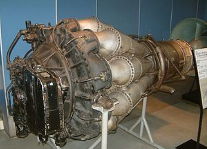
In 1940 the Air Ministry placed a contract with the Gloster Aircraft Company for prototypes of a new twin-engined jet fighter aircraft to the requirement of F.9/40, this aircraft became the Gloster Meteor. At the same time Power Jets was authorised to design a new engine that was intended to power the same aircraft. The W.2 was built under contract by the Rover Car Company in the early 1940s. It was originally intended to be produced by Rover as the W.2B/23.
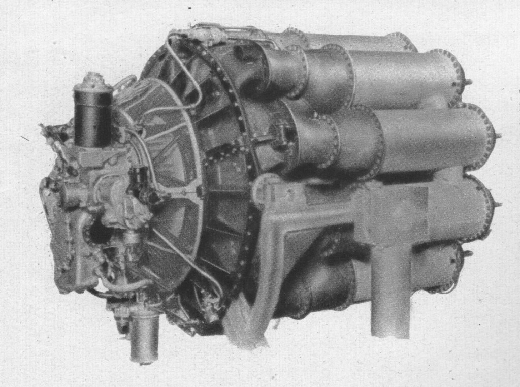
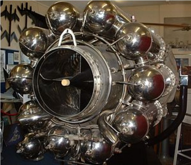
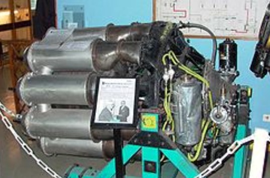
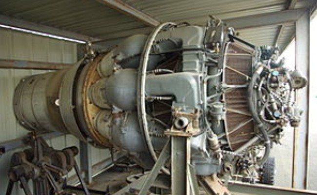
The W.2 was basically a larger version of Whittle’s original flying design, the Whittle Supercharger Type W.1, or simply W.1, which flew in 1941 in the Gloster E. 28/39 experimental testbed aircraft. The engines used a single double-sided centrifugal compressor, or impeller, with the compressed air being taken off at several ports around the extreme outer edge of the compressor disk. They both used Whittle’s “reverse flow” design, in which the flame cans (combustion chambers) were placed around the turbine to produce a shorter engine. This required the heated air to flow forward before reversing its direction to pass through the single-stage axial-flow turbine. For the W.2, the impeller was 19 inches (480 mm) in diameter and there were ten flame cans. Air was bled from the compressor and fed into the inner portion of the turbine for cooling. The entire engine weighed about 850 pounds (390 kilograms).
Whittle was constantly frustrated by Rover. He thought that that there was an inability to deliver production-quality parts, and became increasingly vocal about his complaints. Whittle accused Rover of “tampering” with the design of the engine in order to avoid patent fees and enable Rover to claim the design as their own, whilst Rover’s development work was proceeding at a slow pace. Rover was losing interest in the project after the delays and constant harassment from Whittle. Earlier, in 1940, Stanley Hooker of Rolls-Royce had met Whittle, and later introduced him to Rolls’ CEO, Ernest Hives. Rolls had a fully developed supercharger division, which Hooker directed, which was naturally suited to jet engine work. Hives agreed to supply key parts to help the project along. Eventually, in early 1943, Spencer Wilks of Rover met Hives and Hooker, and decided to trade the jet factory at Barnoldswick for Rolls’ Meteor tank engine factory in Nottingham. A handshake sealed the deal.
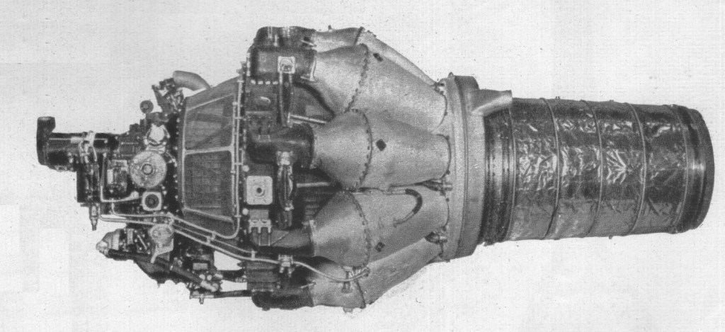
Power Jets W.2/700
Active interest in jet propulsion was first shown by Rolls-Royce during 1938, when a department was established for the design of gas turbines. In 1939 the first projects were put in hand, and by 1940 test rigs for components had been set up. Towards the end of that year the company was making components for Whittle units on behalf of Power Jets, Ltd., and was undertaking the manufacture of turbine blades, casings, pumps and other components.
During 1941 a special test plant was installed, with a Vulture to drive the compressors.
Rover handed over a total of 32 W.2B/23 engines to Rolls-Royce as well as four “straight-through” W.2B/26 engines, developed by Rover’s Adrian Lombard. Rolls-Royce named their engines, and the continuous flow of air through the jets inspired Hooker to name them after the flow of British rivers. The W.2B/23 became the RB.23 Welland (RB standing for Rolls Barnoldswick), and the W.2B/26 became the RB.26 Derwent. Adrian Lombard moved with the engines from Rover to Rolls-Royce. Stanley Hooker helped in the task of ironing out the remaining problems, and things soon improved. A flight-quality /23 was fitted to a Gloster G.40, an updated version of the E.28 that had flown the W.1, and was flown by John Grierson on 1 March 1943. Starting in April, the ratings had been improved to 1,526 lbf (6.79 kN) thrust, and passed a run at 1,600 lbf (7.1 kN) on 7 May 1943. The prototype F.9/40 was finally fitted with 1,700 lbf (7.6 kN) engines and was flown by Michael Daunt on 24 July 1943.
The first Rolls-Royce turbojet, known as the WR1, measured 54in in diameter and was designed for a thrust of 2,000 lb. Built primarily to demonstrate that the aircraft gas turbine could be made cornpletely reliable, it ran for some 35 hr. Two examples were built, but combustion trouble was experienced.
Rolls-Royce there upon assumed control of the W.2 project, with Frank Whittle and his small team at Power Jets acting in an advisory capacity. Together, they ironed out the problems with the W.2 and finally put the engine into mass production as the 1600lbf thrust Rolls-Royce Welland. These engines were installed in the Gloster Meteor F Mk1 and early F Mk3’s and entered service in 1944.
Early in 1943 Rolls-Royce took over research on the W2B/23 unit from the Rover company, whose engineers had developed straight-through combustion; units of the type were installed in the Gloster E.28/39 experimental aircraft, and in the tails of two Vickers-Armstrongs Wellingtons. Like the earlier Power Jets W.1, the trombone configuration featured a simple double-sided centrifugal compressor, reverse-flow combustion chambers and an air-cooled axial-flow turbine section. The first Rolls-Royce/Whittle W2B/23 passed its 100-hr type-test in April 1943, and was given the name Welland; in June 1943 two were fitted in the Gloster F.9/40 (prototype of the Meteor), and by May 1944 Wellands were being regularly delivered for R.A.F. Meteors. The Welland had a reverse-flow combustion system, a maximum diameter of 43in and could develop 1,700 lb, although for the F9/40 it was at first derated to 1,450 lb.
Rolls-Royce Welland
The Halford H1 development was not held up like the W2/B hence it powered the the first Meteor to fly on the 5th March 1943 beating the Rover W2/B 23 powered DG205 by a week.
The first examples produced by Rover had serious problems with “surging”, in which the speed of the engine would suddenly increase out of control. Maurice Wilks eventually delivered a solution, by adding a set of 20-vane diffusers to the exhaust area. This solved the surging, but they now found that they had serious problems with the turbines failing, due to heat. J.P. Herriot of the Air Inspection Department (A.I.D.) was sent to Rover to provide improved turbine materials, and soon the engine achieved a 25-hour test at 1,250 lbf (5.6 kN) in November 1942. Meanwhile, the prototype Gloster F.9/40, soon to be known as the Meteor, was ready for flight, although the engines were not. Taxi tests were started by test pilot Jerry Sayer while the flight-quality engines waited. A real flight-test of the engine itself took place on 9 August 1942, fitted in the tail of a Vickers Wellington bomber.
Two Wellands were installed in the first production Meteor Mk.1, Serial number EE210/G, (the “/G” signifying “Guard”, meaning that the aircraft was to have an armed guard at all times while on the ground) which was test flown by Daunt on 12 January 1944. This Meteor was then sent to the US in exchange for a General Electric J31 (Power Jets W.1) powered Bell XP-59A Airacomet, RG362/G. The Meteor was first flown at Muroc Army Airfield by John Grierson on 15 April. Several test flights followed, and by December it had been shipped back to the UK. Production of the Meteor continued, with EF211 to 229 and 230 through 244 entering service No. 616 Squadron RAF in May 1944. The Wellands were rated at 1,600 lbf (7.1 kN), with 180 hours between overhauls. The Jumo 004B, which entering service only a few weeks earlier, was rated at 1,984 lbf (8.8 kN), but required overhaul after 10–20 hours. Flying from RAF Manston, near the English Channel, the 616 first saw action against the V-1 flying bombs en route to London on 27 July 1944.
From October 1943 a total of 167 Wellands were dispatched from the Rolls-Royce facility at Barnoldswick. By this point, Adrian Lombard’s straight-through design, which became the Rolls-Royce Derwent, had proved to be both more reliable and somewhat more powerful, and production of the Welland ended.
Variants:
W.2 Design thrust of 1600 lbf and a dry weight of approximately 850lb. Early versions could not exceed 1000lbf thrust without compressor surge.
W.2Y Direct flow combustion chamber design, May 1940, unbuilt.
W.2B Rover developed unit.
W.2/700 New compressor diffuser, improved compressor rotor and a static thrust of 2,000 lbf at 16,700 rpm.
W.2/800
W.2/850 A developed version of greater thrust of 2,485 lbf (1,127 kgf) at 16,500 rpm and a higher dry weight of 950lb (431 kg).
Rolls-Royce Welland Mass produced version of the W.2. Developed 1600lbf static thrust. 167 built
Applications: The following aircraft were used for test purposes only: Gloster E.28/39 F.9/40 Vickers Wellington
Production aircraft: Gloster Meteor
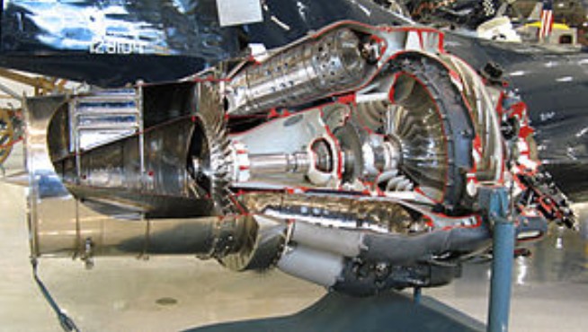
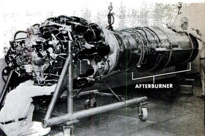
The W.2B/700 was to be used in the Miles M.52 supersonic research aircraft. In order to achieve the thrust required for supersonic flight, a version of the engine was developed using a turbine-driven “augmenter” ducted fan (an early form of turbofan). The NO.4 augmenter was mounted behind the engine, drawing fresh air through ducts surrounding the engine. Power was boosted even further by supplying the air to the world’s first “reheat jetpipe” or afterburner which was actually a very early athodyd or ramjet. The hope was that this combination of the W.2/700, turbofan augmenter and re-heat/ramjet would produce the required power for the proposed 1,000mph aircraft.
Rolls-Royce Trent is the name given to a family of three-spool, high bypass turbofan aircraft engines manufactured by Rolls-Royce plc. All are developments of the RB211 with thrust ratings of 53,000 to 95,000 pounds-force (240 to 420 kN). The Trent has also been adapted for marine and industrial applications.
When Rolls-Royce was privatised in April 1987, its share of the large civil turbofan market was only 8%. Despite increasing sales success with the RB211, General Electric and Pratt & Whitney still dominated the market. At that time, the aircraft manufacturers were proposing new planes that would require unprecedented levels of thrust. Furthermore the Boeing 777 and Airbus A330 were to be twin-engined, and their airline customers were demanding that they be capable of operating in the Extended-range Twin-engine Operations (ETOPS) environment at the time of their initial introduction into service.
Rolls-Royce decided that to succeed in the large engine market of the future, it would have to offer engines for every large civil airliner. In view of the enormous development costs required to bring a new engine to market, the only way to do this would be to have a family of engines based on a common core. The three-shaft design of the RB211 was an ideal basis for the new family as it provided flexibility, allowing the high-pressure (HP), intermediate-pressure (IP) and low-pressure (LP) systems to be individually scaled. Freed from the restrictions of state ownership Rolls decided to launch a new family of engines, which was formally announced at the 1988 Farnborough Airshow. Reviving a name last used 30 years earlier, the new engine was named the Trent. The Trent name had been used for two previous Rolls-Royce engines. The first Trent was the world’s first turboprop engine. The name was reused again in the 1960s for the RB203 bypass turbofan designed to replace the Spey. Rated at 9,980 lbf (44.4 kN) it was the first three-spool engine, forerunner of the RB211 series, but it never entered service.
Rolls-Royce has obtained significant sums of “launch investment” from the British government for the Trent programmes, including £200 million approved in 1997 for Trent 8104, 500 and 600 and £250 million for Trent 600 and 900 in 2001. No aid was sought for Trent 1000. Launch investment is repaid to the government by a royalty on each engine sold.
Like its RB211 predecessor, the Trent uses a three-spool design rather than the more common two-spool configuration. Although inherently more complex, it results in a shorter, more rigid engine which suffers less performance degradation in service than an equivalent twin-spool. The advantage three spools gives is that the front-most fan (driven by the third, rearmost turbine) can be tuned to rotate at its optimal (fairly low) speed; the two compressors are driven by the two other turbines via their spools. The three spools are concentric, of course, like a matryoshka doll.
All the engines in the Trent family share a similar layout, but their three-spool configuration allows each engine module to be individually scaled to meet a wide range of performance and thrust requirements. For example, the large 116-inch (290 cm) diameter fan of the Trent 900 keeps the mean jet velocity at take-off at a relatively low level to help meet the stringent noise levels required by the Airbus A380’s customers. Similarly, core size changes enable the (High Pressure) turbine rotor inlet temperature to be kept as low as possible, thereby minimising maintenance costs. The overall pressure ratio of the Trent 800 is higher than the 700’s despite sharing the same HP system and Intermediate Pressure turbine; this was achieved by increasing the capacity of the IP compressor and the Low Pressure turbine.
Trent engines use hollow titanium fan blades with an internal Warren-girder structure to achieve strength, stiffness and robustness at low weight. The blades can rotate at 3300 RPM with a tip speed of 1730 km/h, well above the speed of sound. The single-crystal nickel alloy turbine blades are also hollow, and air is pushed through laser-drilled holes in them to cool them because the gas temperature is higher than the melting point of the blades. They each remove up to 560 kW from the gas stream.
The completely redesigned core turbomachinery delivers better performance, noise and pollution levels than the RB211. So significant are the improvements that Rolls-Royce fitted the Trent 700’s improved HP system to the RB211-524G and -524H, creating -524G-T and -524H-T respectively.
When the RB211 programme originally started, it was intended that none of the compression system would require variable stators, unlike the American competition. Unfortunately, it was found that, because of the shallow working line on the Intermediate Pressure Compressor (IPC), at least one row of variable stators was required on the IPC, to improve its surge margin at throttled conditions. This feature has been retained throughout the RB211 and Trent series. Although the original intent was not met, Rolls-Royce eliminated the need for many rows of variable stators, with all its inherent complexity, thereby saving weight, cost and improving reliability.
First run in August 1990 as the model Trent 700, the Trent has achieved significant commercial success, having been selected as the launch engine for both of the 787’s variants (Trent 1000), the A380 (Trent 900) and the A350 (Trent XWB). Its overall share of the markets in which it competes is around 40%. Sales of the Trent family of engines have made Rolls-Royce the second biggest supplier of large civil turbofans after General Electric, relegating rival Pratt & Whitney to third position.
On 17 January 2008, a British Airways Boeing 777-236ER, operating as BA038 from Beijing to London, crash-landed at Heathrow after both Trent 800 engines lost power during the aircraft’s final approach. The subsequent investigation found that ice released from the fuel system had accumulated on the fuel-oil heat exchanger, leading to a restriction of fuel flow to the engines. This resulted in Airworthiness Directives mandating the replacement of the heat exchanger. This order was extended to the 500 and 700 series engines after a similar loss of power was observed on one engine of an Airbus A330 in one incident, and both engines in another. The modification involves replacing a face plate with many small protruding tubes with one that is flat.
The initial variant, the Trent 600, was to power the McDonnell Douglas MD-11 with British Caledonian as the engine’s launch customer. However, British Airways cancelled the MD-11 order when it acquired British Caledonian in 1987. With the collapse in 1991 of Air Europe in the aftermath of the 1990-91 Gulf War, the only other Trent-powered MD-11 customer was lost. As the MD-11 was itself suffering poor sales due to its failure to meet its performance targets, the Trent 600 was downgraded to a demonstrator programme, engine development being switched to the Trent 700 for the Airbus A330.
Rolls-Royce Trent 700 In April 1989, Cathay Pacific became the first customer to specify an Airbus aircraft powered by Rolls-Royce engines when it ordered ten A330s powered by the Trent 700. The following month Trans World Airlines followed suit with an order for twenty A330s.
The Trent 700 first ran in August 1990, and certification was achieved in January 1994. 90 minutes ETOPS approval was achieved in March 1995, and this was extended to 120 minutes in December 1995 and 180 minutes in May 1996.
Rolls-Royce Trent 800 At the same time, Boeing was investigating an enlarged development of its 767 model dubbed the 767X, for which Rolls-Royce proposed the Trent 760. By 1990 Boeing abandoned its planned 767X and instead decided to launch a new, larger aircraft family designated 777 with a thrust requirement of 80,000 lbf (360 kN) or more. The Trent 700’s 2.47 m (97 in) diameter fan would not be big enough to meet this requirement, so Rolls proposed a new version with a 2.80 m (110 in) fan diameter, designated Trent 800.
Testing of the Trent 800 began in September 1993, and certification was achieved in January 1995. The first Boeing 777 with Trent 800 engines flew in May 1995, and entered service with Cathay Pacific in April 1996.
Initially Rolls-Royce had difficulty selling the engine; British Airways, traditionally a Rolls-Royce customer, submitted a large order for the competing General Electric GE90 engine. The breakthrough came when it won orders from Singapore Airlines, previously a staunch Pratt & Whitney customer, for its 34 Boeing 777s. The Trent 800 has a 41% share of the engine market on the 777 variants for which it is available.
In 1998 Boeing proposed new longer range variants of the 777X. Taking advantage of the Trent 800’s growth capability, Rolls-Royce designed and built an improved engine designated Trent 8104, which was later scaled upwards to the even larger 8115. This development was the first engine to break through 100,000 lbf (440 kN) thrust and subsequently the first to reach 110,000 lbf (490 kN). However, GE Aviation former president James McNerney (now Boeing CEO) successfully offered the aircraft manufacturer up to $500 million in money to develop the 777X in exchange for exclusivity in powering the family. Boeing agreed in July 1999 to such a deal with the GE90-110B and GE90-115B to be the sole engines on the long-range 777s. This resulted in the 8104 becoming just a demonstrator programme, despite setting further industry firsts for thrust levels achieved and the first to demonstrate the use of a fully swept wide chord fan.
Rolls-Royce Trent 500 In 1995, Airbus began considering an engine for two new long-range derivatives of its four-engine A340 aircraft, designated A340-500/-600. In April 1996, Airbus signed an agreement with General Electric to develop a suitable engine, but decided not to proceed when GE demanded an exclusivity deal on the A340. After a contest with Pratt & Whitney, Airbus announced on 15 June 1997 at the Paris Air Show that it had selected the Trent 500 to power the A340-500 and -600. Two year later, in May 1999, the Trent 500 first ran and certification was achieved in December 2000. It entered service on the A340-600 with Virgin Atlantic Airways in July 2002 and on the ultra-long range A340-500 with Emirates in December 2003.
As of January 2009, firm orders had been received from 15 customers for 139 A340s powered by Trent 500s; Lufthansa was the largest operator, with 21 in service.
In 1999 a derivative of the Trent 892, the Trent 895 received certification from both the UK and the European authorities. The 95,000 lb thrust engine was scheduled for British Airways Boeing 777-200s.
Rolls-Royce Trent 900
Rolls-Royce Trent 900 on testIn the early 1990s, Airbus had begun development of a larger successor to the Boeing 747, an aircraft designated A3XX, which was later to be formally launched as the Airbus A380. By 1996, its definition had progressed to the extent that Rolls-Royce was able to announce that it would develop the Trent 900 to power the A380. In October 2000, the Trent 900 became the A380’s launch engine when Singapore Airlines specified the engine for its order for 10 A380s; this was quickly followed by Qantas in February 2001.
The Trent 900 first ran on May 17, 2004 on Airbus’ A340-300 testbed, replacing the port inner CFM56-5 engine, and its final certification was granted by the European Aviation Safety Agency (EASA) on 29 October 2004 and the Federal Aviation Administration (FAA) on 4 December 2006. Rolls-Royce announced in October 2007 that production of the Trent 900 had been restarted after a twelve month suspension caused by delays to the A380.
On 27 September 2007, British Airways announced the selection of the Trent 900 to power 12 A380 aircraft, helping to take the engine’s share of the A380 engine market to 52% at the end of February 2009.
On 4 November 2010, a Trent 900 experienced an uncontained failure on Qantas Flight 32 over Singapore. After investigation, Rolls-Royce announced the problem was specific to the Trent 900, and in particular unrelated to failure of a Trent 1000 under test. However, others have noted that although the specific part may be only found in the 900, in both cases the intermediate pressure turbine and lubrication system are suspect.
In July 2000, Rolls-Royce signed an agreement with Boeing to offer the Trent 600 engine on developments of 767 and 747 aircraft. The 767 variant was to be a new longer-range version of the Boeing 767-400ER to be powered by the Trent 600 and Engine Alliance GP7172, although in the end this aircraft was never launched. When Boeing finally launched the 747-8 in 2005 it announced that the General Electric GEnx would be the only engine available for the 747-8.
On 6 April 2004 Boeing announced that it had selected two engine partners for its new 787, Rolls-Royce and General Electric. Initially, Boeing toyed with the idea of sole sourcing the powerplant for the 787, with GE being the most likely candidate. However, potential customers demanded choices and Boeing relented. For the first time in commercial aviation, both engine types will have a standard interface with the aircraft, allowing any 787 to be fitted with either a GE or Rolls-Royce engine at any time as long as the pylon is also modified.
In June 2004, the first public engine selection was made by Air New Zealand, who chose the Trent 1000 for its two firm orders. In the largest 787 order, that of Japan’s All Nippon Airways, Rolls-Royce was selected as the engine supplier on October 13, 2004. The deal is valued at $1 billion (£560 million) and covers 30 787-3s and 20 787-8s. The Trent 1000 will be the launch engine on all three current 787 models, the -8 with ANA and the -9 with Air New Zealand. On 7 July 2007, Rolls Royce secured its largest ever order from an aircraft leasing company when ILFC placed an order worth $1.3 billion at list prices for Trent 1000s to power 40 of the 787s which it has on order, and on 27 September 2007 British Airways announced the selection of the Trent 1000 to power 24 Boeing 787 aircraft. Trent 1000’s share of the 787 engine market was 40% at the end of August 2008.
The first run of the Trent 1000 was on 14 February 2006, with first flight on Rolls-Royce’s own flying testbed (a modified Boeing 747-200) successfully performed on June 18, 2007 from TSTC Waco Airport in Waco, TX. The engine received joint certification from the FAA and EASA on 7 August 2007 (written 7/8/7 outside the US). Entry into service has been delayed by more than two years to the last quarter of 2010 following a series of delays to the Boeing 787 programme. The Trent 1000, along with the General Electric GEnx, is distinguished from other turbofans with the use of noise-reducing chevrons on the engine nacelle when in use.
A Trent 500 replacement engine, known unofficially as the Trent 1500, was proposed for the Airbus A340-500/600 to help them compete with the Boeing 777-200LR/300ER. However, the announcement of the A350 XWB, which covers the A340 market, will most likely prevent the Trent 1500 from ever becoming a reality.
The Trent 1500 would retain the 2.47-metre (8 ft 1 in) fan diameter of the current Trent 500 engine, as well as the nacelle, but incorporates the smaller, more advanced, Trent 1000/XWB gas generator and LP turbine, suitably modified.
The Trent XWB is a series of turbofan engines, developed from the RB211 and it is used exclusively for the Airbus A350 XWB
Major applications: Airbus A330 Airbus A340 (-500 and -600 series only) Airbus A350 Airbus A380 Boeing 777 (-200, -200ER and -300 series only) Boeing 787 Dreamliner
Trent 553 Three-shaft high bypass ratio: 9.3 Fan diameter: 3.0 m (118 in) Fan: single stage, swept, low hub:tip ratio Airflow: approx. 1,440 kg (3,200 lb) per second Overall pressure ratio >=52:1 (Top-of-Climb) IP compressor: 8 stage axial HP compressor: 6 stage axial Static Thrust: 53,000 lbf Basic Engine Weight: 10,400 lb Thrust to Weight Ratio: 5.1 Length: 154 in Fan Diameter: 97.4 in Entry Into Service: 2003 Applications: Airbus A340-500
Trent 556 Three-shaft high bypass ratio: 9.3 Fan diameter: 3.0 m (118 in) Fan: single stage, swept, low hub:tip ratio Airflow: approx. 1,440 kg (3,200 lb) per second Overall pressure ratio >=52:1 (Top-of-Climb) IP compressor: 8 stage axial HP compressor: 6 stage axial Static Thrust: 56,000 lbf Basic Engine Weight: 10,400 lb Thrust to Weight Ratio: 5.4 Length: 154 in Fan Diameter: 97.4 in Entry Into Service: 2002 Applications: Airbus A340-500, Airbus A340-600
Trent 560 Three-shaft high bypass ratio: 9.3 Fan diameter: 3.0 m (118 in) Fan: single stage, swept, low hub:tip ratio Airflow: approx. 1,440 kg (3,200 lb) per second Overall pressure ratio >=52:1 (Top-of-Climb) IP compressor: 8 stage axial HP compressor: 6 stage axial Static Thrust: 60,000 lbf Basic Engine Weight: 10,400 lb Thrust to Weight Ratio: 5.76 Length: 154 in Fan Diameter: 97.4 in Entry Into Service: 2002 Applications: Airbus A340-600
Trent 600 Three-shaft high bypass ratio: 9.3 Fan diameter: 3.0 m (118 in) Fan: single stage, swept, low hub:tip ratio Airflow: approx. 1,440 kg (3,200 lb) per second Overall pressure ratio >=52:1 (Top-of-Climb) IP compressor: 8 stage axial HP compressor: 6 stage axial Static Thrust: 65,000 lbf Basic Engine Weight: 10,400 lb Thrust to Weight Ratio: 6.3 Length: 154 in Fan Diameter: 97.4 in Entry Into Service: Not Used
Trent 768 Three-shaft high bypass ratio: 9.3 Fan diameter: 3.0 m (118 in) Fan: single stage, swept, low hub:tip ratio Airflow: approx. 1,440 kg (3,200 lb) per second Overall pressure ratio >=52:1 (Top-of-Climb) IP compressor: 8 stage axial HP compressor: 6 stage axial Static Thrust: 67,500 lbf Basic Engine Weight: 10,550 lb Thrust to Weight Ratio: 6.4 Length: 154 in Fan Diameter: 97.4 in Entry Into Service: 1996 Applications: Airbus A330-200, Airbus A330-300
Trent 772 Three-shaft high bypass ratio: 9.3 Fan diameter: 3.0 m (118 in) Fan: single stage, swept, low hub:tip ratio Airflow: approx. 1,440 kg (3,200 lb) per second Overall pressure ratio >=52:1 (Top-of-Climb) IP compressor: 8 stage axial HP compressor: 6 stage axial Static Thrust: 71,100 lbf Basic Engine Weight: 10,550 lb Thrust to Weight Ratio: 6.7 Length: 154 in Fan Diameter: 97.4 in Entry Into Service: 1994 Applications: Airbus A330-200, Airbus A330-300
Trent 772B Three-shaft high bypass ratio: 9.3 Fan diameter: 3.0 m (118 in) Fan: single stage, swept, low hub:tip ratio Airflow: approx. 1,440 kg (3,200 lb) per second Overall pressure ratio >=52:1 (Top-of-Climb) IP compressor: 8 stage axial HP compressor: 6 stage axial Static Thrust: 71,100 lbf Basic Engine Weight: 10,550 lb Thrust to Weight Ratio: 6.7 Length: 154 in Fan Diameter: 97.4 in Entry Into Service: 1998 Applications: Airbus A330-200, Airbus A330-300
Trent 772C Three-shaft high bypass ratio: 9.3 Fan diameter: 3.0 m (118 in) Fan: single stage, swept, low hub:tip ratio Airflow: approx. 1,440 kg (3,200 lb) per second Overall pressure ratio >=52:1 (Top-of-Climb) IP compressor: 8 stage axial HP compressor: 6 stage axial Static Thrust: 71,100 lbf Basic Engine Weight: 10,550 lb Thrust to Weight Ratio: 6.7 Length: 154 in Fan Diameter: 97.4 in Entry Into Service: 2007 Applications: Airbus A330-200, Airbus A330-300
Trent 875 Three-shaft high bypass ratio: 9.3 Fan diameter: 3.0 m (118 in) Fan: single stage, swept, low hub:tip ratio Airflow: approx. 1,440 kg (3,200 lb) per second Overall pressure ratio >=52:1 (Top-of-Climb) IP compressor: 8 stage axial HP compressor: 6 stage axial Static Thrust: 75,000 lbf Basic Engine Weight: 13,100 lb Thrust to Weight Ratio: 5.7 Length: 172 in Fan Diameter: 110 in Entry Into Service: 1995 Applications: Boeing 777-200
Trent 877 Three-shaft high bypass ratio: 9.3 Fan diameter: 3.0 m (118 in) Fan: single stage, swept, low hub:tip ratio Airflow: approx. 1,440 kg (3,200 lb) per second Overall pressure ratio >=52:1 (Top-of-Climb) IP compressor: 8 stage axial HP compressor: 6 stage axial Static Thrust: 77,000 lbf Basic Engine Weight: 13,100 lb Thrust to Weight Ratio: 5.9 Length: 172 in Fan Diameter: 110 in Entry Into Service: 1996 Applications: Boeing 777-200
Trent 884 Three-shaft high bypass ratio: 9.3 Fan diameter: 3.0 m (118 in) Fan: single stage, swept, low hub:tip ratio Airflow: approx. 1,440 kg (3,200 lb) per second Overall pressure ratio >=52:1 (Top-of-Climb) IP compressor: 8 stage axial HP compressor: 6 stage axial Static Thrust: 84,000 lbf Basic Engine Weight: 13,100 lb Thrust to Weight Ratio: 6.4 Length: 172 in Fan Diameter: 110 in Entry Into Service: 1997 Applications: Boeing 777-200ER
Trent 890 Three-shaft high bypass ratio: 9.3 Fan diameter: 3.0 m (118 in) Fan: single stage, swept, low hub:tip ratio Airflow: approx. 1,440 kg (3,200 lb) per second Overall pressure ratio >=52:1 (Top-of-Climb) IP compressor: 8 stage axial HP compressor: 6 stage axial Static Thrust: 90,000 lbf Basic Engine Weight: 13,100 lb Thrust to Weight Ratio: 6.9 Length: 172 in Fan Diameter: 110 in Entry Into Service: 1998 Applications: Boeing 777-200ER
Trent 892 Three-shaft high bypass ratio: 9.3 Fan diameter: 3.0 m (118 in) Fan: single stage, swept, low hub:tip ratio Airflow: approx. 1,440 kg (3,200 lb) per second Overall pressure ratio >=52:1 (Top-of-Climb) IP compressor: 8 stage axial HP compressor: 6 stage axial Static Thrust: 92,000 lbf Basic Engine Weight: 13,100 lb Thrust to Weight Ratio: 7.0 Length: 172 in Fan Diameter: 110 in Entry Into Service: 1997 Applications: Boeing 777-200ER, Boeing 777-300
Trent 895 Three-shaft high bypass ratio: 9.3 Fan diameter: 3.0 m (118 in) Fan: single stage, swept, low hub:tip ratio Airflow: approx. 1,440 kg (3,200 lb) per second Overall pressure ratio >=52:1 (Top-of-Climb) IP compressor: 8 stage axial HP compressor: 6 stage axial Static Thrust: 93,400 lbf Basic Engine Weight: 13,100 lb Thrust to Weight Ratio: 7.1 Length: 172 in Fan Diameter: 110 in Entry Into Service: 1999 Applications: Boeing 777-200ER
Trent 8104 Three-shaft high bypass ratio: 9.3 Fan diameter: 3.0 m (118 in) Fan: single stage, swept, low hub:tip ratio Airflow: approx. 1,440 kg (3,200 lb) per second Overall pressure ratio >=52:1 (Top-of-Climb) IP compressor: 8 stage axial HP compressor: 6 stage axial Static Thrust: 104,000 lbf Basic Engine Weight: 14,400 lb Thrust to Weight Ratio: 7.2 Length: 172 in Fan Diameter: in Entry Into Service: 110
Trent 8115 Three-shaft high bypass ratio: 9.3 Fan diameter: 3.0 m (118 in) Fan: single stage, swept, low hub:tip ratio Airflow: approx. 1,440 kg (3,200 lb) per second Overall pressure ratio >=52:1 (Top-of-Climb) IP compressor: 8 stage axial HP compressor: 6 stage axial Static Thrust: 115,000 lbf Length: 172 in Fan Diameter: 120 in Entry Into Service: Not Used
Trent 970 Three-shaft high bypass ratio: 9.3 Fan diameter: 3.0 m (118 in) Fan: single stage, swept, low hub:tip ratio Airflow: approx. 1,440 kg (3,200 lb) per second Overall pressure ratio >=52:1 (Top-of-Climb) IP compressor: 8 stage axial HP compressor: 6 stage axial Static Thrust: 75,152 lbf Basic Engine Weight: 13,842 lb Thrust to Weight Ratio: 5.4 Length: 179 in Fan Diameter: 116 in Entry Into Service: 2007 Applications: Airbus A380-841
Trent 970B Three-shaft high bypass ratio: 9.3 Fan diameter: 3.0 m (118 in) Fan: single stage, swept, low hub:tip ratio Airflow: approx. 1,440 kg (3,200 lb) per second Overall pressure ratio >=52:1 (Top-of-Climb) IP compressor: 8 stage axial HP compressor: 6 stage axial Static Thrust: 78,304 lbf Basic Engine Weight: 13,842 lb Thrust to Weight Ratio: 5.6 Length: 179 in Fan Diameter: 116 in Entry Into Service: 2008 Applications: Airbus A380-841
Trent 972 Three-shaft high bypass ratio: 9.3 Fan diameter: 3.0 m (118 in) Fan: single stage, swept, low hub:tip ratio Airflow: approx. 1,440 kg (3,200 lb) per second Overall pressure ratio >=52:1 (Top-of-Climb) IP compressor: 8 stage axial HP compressor: 6 stage axial Static Thrust: 76,752 lbf Basic Engine Weight: 13,842 lb Thrust to Weight Ratio: 5.5 Length: 179 in Fan Diameter: 116 in Applications: Airbus A380-842
Trent 972B Three-shaft high bypass ratio: 9.3 Fan diameter: 3.0 m (118 in) Fan: single stage, swept, low hub:tip ratio Airflow: approx. 1,440 kg (3,200 lb) per second Overall pressure ratio >=52:1 (Top-of-Climb) IP compressor: 8 stage axial HP compressor: 6 stage axial Static Thrust: 80,231 lbf Basic Engine Weight: 13,842 lb Thrust to Weight Ratio: 5.8 Length: 179 in Fan Diameter: 116 in Applications: Airbus A380-842
Trent 977 Three-shaft high bypass ratio: 9.3 Fan diameter: 3.0 m (118 in) Fan: single stage, swept, low hub:tip ratio Airflow: approx. 1,440 kg (3,200 lb) per second Overall pressure ratio >=52:1 (Top-of-Climb) IP compressor: 8 stage axial HP compressor: 6 stage axial Static Thrust: 80,781 lbf Basic Engine Weight: 13,842 lb Thrust to Weight Ratio: 5.8 Length: 179 in Fan Diameter: 116 in Applications: Airbus A380-843F
Trent 977B Three-shaft high bypass ratio: 9.3 Fan diameter: 3.0 m (118 in) Fan: single stage, swept, low hub:tip ratio Airflow: approx. 1,440 kg (3,200 lb) per second Overall pressure ratio >=52:1 (Top-of-Climb) IP compressor: 8 stage axial HP compressor: 6 stage axial Static Thrust: 83,835 lbf Basic Engine Weight: 13,842 lb Thrust to Weight Ratio: 6.0 Length: 179 in Fan Diameter: 116 in Applications: Airbus A380-843F
Trent 980-84 Three-shaft high bypass ratio: 9.3 Fan diameter: 3.0 m (118 in) Fan: single stage, swept, low hub:tip ratio Airflow: approx. 1,440 kg (3,200 lb) per second Overall pressure ratio >=52:1 (Top-of-Climb) IP compressor: 8 stage axial HP compressor: 6 stage axial Static Thrust: 84,098 lbf Basic Engine Weight: 13,842 lb Thrust to Weight Ratio: 6.0 Length: 179 in Fan Diameter: 116 in Applications: Airbus A380-941
Trent 1000-A Three-shaft high bypass ratio: 9.3 Fan diameter: 3.0 m (118 in) Fan: single stage, swept, low hub:tip ratio Airflow: approx. 1,440 kg (3,200 lb) per second Overall pressure ratio >=52:1 (Top-of-Climb) IP compressor: 8 stage axial HP compressor: 6 stage axial Static Thrust: 63,800 lbf Basic Engine Weight: 11,924 lb Thrust to Weight Ratio: 5.4 Length: 160 in Fan Diameter: 112 in Entry Into Service: 2009 Applications: Boeing 787-8
Trent 1000-C Three-shaft high bypass ratio: 9.3 Fan diameter: 3.0 m (118 in) Fan: single stage, swept, low hub:tip ratio Airflow: approx. 1,440 kg (3,200 lb) per second Overall pressure ratio >=52:1 (Top-of-Climb) IP compressor: 8 stage axial HP compressor: 6 stage axial Static Thrust: 69,800 lbf Basic Engine Weight: 11,924 lb Thrust to Weight Ratio: 5.9 Length: 160 in Fan Diameter: 112 in Entry Into Service: 2009 Applications: Boeing 787-8, Boeing 787-9
Trent 1000-D Three-shaft high bypass ratio: 9.3 Fan diameter: 3.0 m (118 in) Fan: single stage, swept, low hub:tip ratio Airflow: approx. 1,440 kg (3,200 lb) per second Overall pressure ratio >=52:1 (Top-of-Climb) IP compressor: 8 stage axial HP compressor: 6 stage axial Static Thrust: 69,800 lbf Basic Engine Weight: 11,924 lb Thrust to Weight Ratio: 5.9 Length: 160 in Fan Diameter: 112 in Entry Into Service: 2009 Applications: Boeing 787-8, Boeing 787-9
Trent 1000-E Three-shaft high bypass ratio: 9.3 Fan diameter: 3.0 m (118 in) Fan: single stage, swept, low hub:tip ratio Airflow: approx. 1,440 kg (3,200 lb) per second Overall pressure ratio >=52:1 (Top-of-Climb) IP compressor: 8 stage axial HP compressor: 6 stage axial Static Thrust: 53,200 lbf Basic Engine Weight: 11,924 lb Thrust to Weight Ratio: 4.5 Length: 160 in Fan Diameter: 112 in Entry Into Service: 2009 Applications: Boeing 787-3
Trent 1000-H Three-shaft high bypass ratio: 9.3 Fan diameter: 3.0 m (118 in) Fan: single stage, swept, low hub:tip ratio Airflow: approx. 1,440 kg (3,200 lb) per second Overall pressure ratio >=52:1 (Top-of-Climb) IP compressor: 8 stage axial HP compressor: 6 stage axial Static Thrust: 58,000 lbf Basic Engine Weight: 11,924 lb Thrust to Weight Ratio: 4.9 Length: 160 in Fan Diameter: 112 in Entry Into Service: 2009 Applications: Boeing 787-3, Boeing 787-8
Trent 1000-J Three-shaft high bypass ratio: 9.3 Fan diameter: 3.0 m (118 in) Fan: single stage, swept, low hub:tip ratio Airflow: approx. 1,440 kg (3,200 lb) per second Overall pressure ratio >=52:1 (Top-of-Climb) IP compressor: 8 stage axial HP compressor: 6 stage axial Static Thrust: 73,800 lbf Basic Engine Weight: 11,924 lb Thrust to Weight Ratio: 6.2 Length: 160 in Fan Diameter: 112 in Entry Into Service: 2010 Applications: Boeing 787-9
Trent 1000-K Three-shaft high bypass ratio: 9.3 Fan diameter: 3.0 m (118 in) Fan: single stage, swept, low hub:tip ratio Airflow: approx. 1,440 kg (3,200 lb) per second Overall pressure ratio >=52:1 (Top-of-Climb) IP compressor: 8 stage axial HP compressor: 6 stage axial Static Thrust: 73,800 lbf Basic Engine Weight: 11,924 lb Thrust to Weight Ratio: 6.2 Length: 160 in Fan Diameter: 112 in Entry Into Service: 2010 Applications: Boeing 787-9
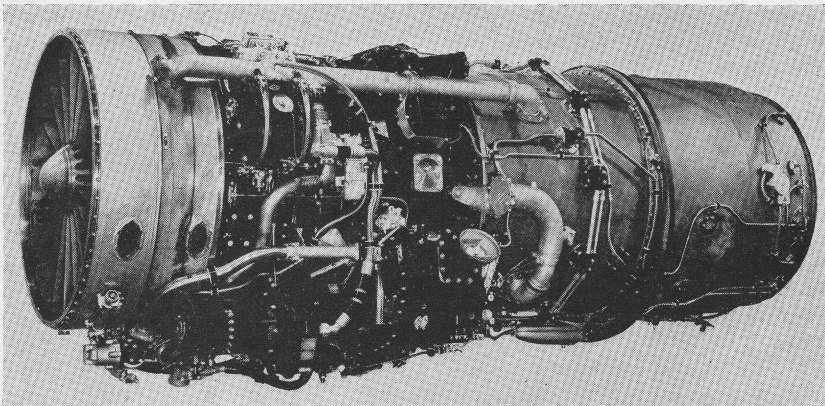
The Tay was developed in the first instance by Rolls-Royce from the basic Nene design. Two units of the type were test-flown in a special Vickers Viscount. It has been further improved by the Pratt and Whitney and HispanoSuiza concerns, which, respectively, hold the American and French licences.
By 1948, Rolls-Royce had designed the Tay turbojet, also a centrifugal-flow design. However, as Rolls-Royce was then developing an improved design with an axial compressor, which would become the Avon, the development and production of the Tay turbojet was left to Pratt & Whitney. However, Rolls-Royce retained the rights to the Tay outside of the United States.
A total of 4,108 were built.
The Tay/J48 was a thirty percent enlargement of the preceding Nene/J42, and was produced both with and without afterburning.
Pratt & Whitney J48
Hispano-Suiza Tays have been installed in Dassault Mystere II, III and IV fighters, and the Tay 250 is for the Mystere IVA. A development of the Tay by the French company is called the Verdon (following the “River” nomenclature) and has a modified compressor with new guide-vanes, revised flame-tubes and combustion chambers, and new turbine-blades and disc. A special afterburner has been developed for this engine, which is to replace the Tay in the Mystere IVA.
Hispano-Suiza Verdon
The new J48 in 1950 powering the North American YF-93A developed 6250 lb thrust, with another 1750 lb with afterburner. It was also planned to power the Navy’s new F9F-5 Panther.
1950 J-48
Variants:
RB.44 Tay Rolls-Royce development engines only, no production.
Hispano-Suiza Verdon The Tay built and developed under licence in France.
Pratt & Whitney J48 The Tay built and developed under licience in the United States. J48-P-1: 6,000 lbf (26.7 kN), 8,000 lbf (35.6 kN) thrust with afterburning J48-P-2: 6,250 lbf (27.8 kN), 7,000 lbf (31.1 kN) thrust with water injection J48-P-3: 6,000 lbf (26.7 kN), 8,000 lbf (35.6 kN) thrust with afterburning J48-P-5: 6,350 lbf (28.2 kN), 8,750 lbf (38.9 kN) thrust with afterburning J48-P-6: 6,250 lbf (27.8 kN), 7,000 lbf (31.1 kN) thrust with water injection J48-P-7: 6,350 lbf (28.2 kN), 8,750 lbf (38.9 kN) thrust with afterburning J48-P-8: 7,250 lbf (32.2 kN) thrust J48-P-8A: 7,250 lbf (32.2 kN) thrust
Applications:
Tay Vickers 663 Tay Viscount
Verdon Dassault Mystère IV
J48 Grumman F9F-5 Panther Grumman F9F-6/F9F-8 Cougar Lockheed F-94C Starfire North American YF-93
Specifications:
Hispano-Suiza Verdon 350 Type: Turbojet Length: 103.2 in (2,621 mm) Diameter: 50 in (1,270 mm) Dry weight: 2,061 lb (935 kg) Compressor: Double sided centrifugal compressor Combustors: Nine tubular combustion chambers Turbine: Single-stage turbine Fuel type: AVTUR / JET-A1 / F-34 etc. Oil system: Pressure spray lubricated with scavenging Maximum thrust: 7,710 lbf (34 kN) at 11,000 rpm Overall pressure ratio: 4.9 Specific fuel consumption: 1.1 lb/lb/hr Thrust-to-weight ratio: 3.74
Pratt & Whitney J48-P-8A Type: Turbojet Length: 202 in (513 cm) Diameter: 50 in (127 cm) Dry weight: 2,101 lb (953 kg) Compressor: Centrifugal compressor Maximum thrust: 7,250 lbf (32.2 kN) thrust
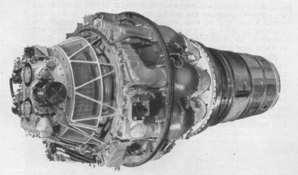
Designed to a Ministry of Aircraft Production specification of 1944, calling for a turbojet having a maximum diameter of 55in, and minimum static thrust of 4,000 lb and a weight not exceeding 2,200 lb, the Nene is the “big brother” of the later Derwents. Consideration was given in the early project stage to the scaling-up of a Derwent to meet the specification, but as this would have entailed increasing the diameter to nearly 60in a new design was put in hand and was completed in 5.5 months. In this the diameter was kept down to 49.5in and a thrust of 5,000 lb was attained.
Although based on the “straight-through” version of the basic Whittle-style layout, the Nene used a double-sided centrifugal compressor for improved pressure ratio and thus higher thrust. It was during the design of the Nene that Rolls decided to give their engines numbers as well as names, with the Welland and Derwent keeping their original Rover models, B/23 and B/26. It was later decided that these model numbers looked too much like those for bombers, and “R” was added to the front, the “R” signifying “Rolls” and the original Rover “B” signifying Barnoldswick. The Nene first ran on 27 October 1944.
The design of the nine combustion chambers follows Derwent practice. Each consists of a cast expansion charnber attached to an outer air-casing containing a flame tube. About 15 per cent of the air entering each chamber is directed by perforated baffles and swirl-vanes in the flame tube into the combustion zone around the burner head. In this zone, where the air is turbulent and moving slowly, the primary air flow, together with a small reverse flow round the flame tube, mixes with the fuel sprayed from the burners and burns at a flame temperature of 1,600-2,000 deg C. To prevent distortion of the flame tube due to local overheating caused by flames impinging on the walls, a thin layer of air is admitted round the inside periphery of the tube through a circular “window piece.” The remaining air flows between the flame tube and air casing, and communicates with the combustion zone through rows of holes in the flame tube. This diluting air is consequently expanded and accelerated rearwards, but it also cools the products of combustion to the temperature required at the turbine inlet.
Early airborne tests of the Nene were undertaken in an Avro Lancastrian operated by Rolls-Royce from their Hucknall airfield. The two outboard Rolls-Royce Merlins were replaced by the jet engine. The Nene’s first flight however was in a modified Lockheed XP-80 Shooting Star.
The Nene doubled the thrust of the earlier generation engines, with early versions providing about 5,000 lbf (22.2 kN), but remained generally similar in most ways. This should have suggested that it would be widely used in various designs, but the Gloster Meteor proved so successful with its Derwents that the Air Ministry felt there was no pressing need to improve upon it. Instead a series of much more capable designs using the Rolls-Royce Avon were studied, and the Nene generally languished.
Marks of Nene include the 3, with electric starter motor and two torch-igniter units (this powers the Supermarine Attacker F.1); the Mk 10, which is similar to the Mk 102 later mentioned but has a larger wheelcase of accessories (this is the engine of the Canadair Silver Star); the Mk 101, specially adapted for the Sea Hawk and having a horizontal gear-box drive, Plessey turbo-starter and divided jet-pipe; and the 102, which is interchangeable with the III but has various design changes, including two high-energy igniters. This last powers the Supermarine Attacker F.B.2. Nenes have also been installed in the Gloster E.1/44, an experimental Lockheed Shooting Star and the Dassault Ouragan.
The Nene was used to power the first civil jet aircraft, a modified Vickers Viking, which flew first on 6 April 1948. The design saw relatively little use in British aircraft designs, being passed over in favour of the axial-flow Avon that followed it. Its only widespread use in Great Britain was in the Hawker Sea Hawk and the Supermarine Attacker.
In 1947, at the behest of the United States Navy, Pratt & Whitney entered into an agreement to produce the Rolls-Royce Nene centrifugal-flow turbojet engine under license as the J42 (company designation JT6), for use in the Grumman F9F Panther fighter aircraft. Concerned that the Nene would not have the potential to cope with future weight growth in improved versions of the Panther, Luke Hobbs, vice president of engineering for P&W’s parent company, the United Aircraft Corporation, requested that Rolls-Royce design a more powerful engine based on the Nene, which Pratt & Whitney would also produce. That engine was the Tay.
Twenty-five were given to the Soviet Union as a gesture of goodwill – with reservation to not use for military purposes – with the agreement of Stafford Cripps. The Soviets reneged on the deal, and reverse engineered the Nene to develop the Klimov RD-45, and a larger version, the Klimov VK-1, which soon appeared in various Soviet fighters including Mikoyan-Gurevich MiG-15.
It was briefly made under licence in Australia for use in the RAAF de Havilland Vampire fighters. It was also built by Orenda in Canada for use in 656 Canadair CT-133 Silver Star aircraft.
Applications: Nene Armstrong Whitworth AW.52 Avro Ashton Avro Lancastrian (test-bed) Avro Tudor VIII Boulton Paul P.111 Boulton Paul P.120 Canadair CT-133 Silver Star Dassault Ouragan de Havilland Vampire FMA IAe 33 Pulqui II Handley Page HP.88 Hawker P.1052 Hawker P.1081 Hawker Sea Hawk Nord 2200 Rolls-Royce Thrust Measuring Rig SNCASO SO.4000 SNCASO SO.6000 Triton Sud-Est Grognard Sud-Ouest Bretagne Sud-Ouest Triton Supermarine Attacker Vickers Type 618 Nene-Viking
Pratt & Whitney J42 Grumman F9F Panther
Specifications: Nene Type: Centrifugal compressor turbojet Length: 96.8 in (2,458.7 mm) Diameter: 49.5 in (1,257.3 mm) Dry weight: 1,600 lb (725.7 kg) Compressor: 1-stage double-sided centrifugal compressor Combustors: 9 x can combustion chambers Turbine: Single-stage axial Fuel type: Kerosene (R.D.E.F./F/KER) Oil system: pressure feed, dry sump with scavenge, cooling and filtration, oil grade 70 S.U. secs (13 cs) (D.T.D 44D) at 38 °C (100 °F) Maximum thrust: 5,000 lbf (22.24 kN) at 12,300 rpm at sea level for take=off Specific fuel consumption: 1.06 lb/lbf/hr (108.04 kg/kN/hr) Thrust-to-weight ratio: 3.226 lbf/lb (0.0315 kN/kg) Military, static: 5,000 lbf (22.24 kN) at 12,300 rpm at sea level Max. cruising, static: 4,360 lbf (19.39 kN) at 12,000 rpm at sea level Cruising, static: 3,620 lbf (16.10 kN) at 11,500 rpm at sea level Idling, static: 120 lbf (0.53 kN) at 2,500 rpm at sea level
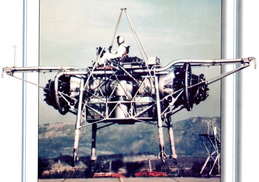
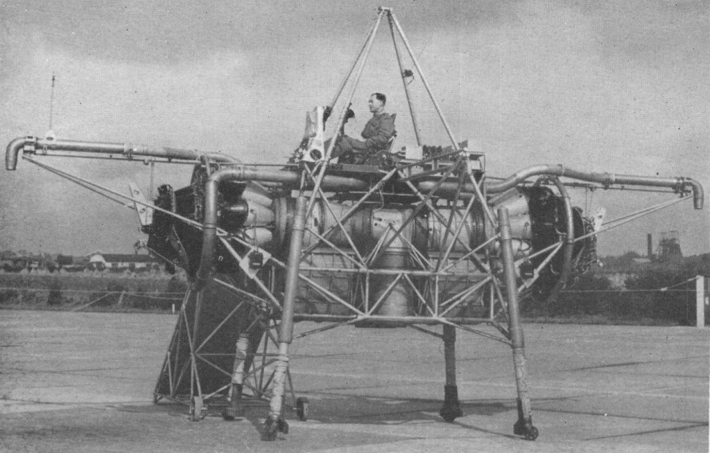
The Bedstead, officially called a Thrust Measuring Rig (TMR), was the brainchild of Doctor A.A.Griffith of Rolls Royce. It was a flat riser which hovered on the deflected exhaust gases of two Rolls Royce Nene jet engines. Compressed air nozzles provided directional control. The data gathered during the Bedsteads’ test programme in the mid 1950s led to the development of a special turbojet engine for jet lift, the RB108.
This was a radically new approach towards the development of vertical take off aircraft. Basically it consists of a tubular frame, said to measure about 20 ft. across, on which are mounted two Nene engines having a common, downward facing tail pipe. Space is also provided for fuel tankage and the pilot is seated in the normal attitude on the top.
The weight amounts to some 3.5 tons, and is a little less than the total maximum thrust from the 5,000 lb. thrust Nenes. The two engines are mounted horizontally, facing away from each other, the exhaust gases being turned through 90 degrees to enter a common downward directed tail pipe. The thrust so obtained provides for direct vertical jet lift of the rig.
Control in the pitch, roll and yaw planes is obtained by means of air jets bled from the Nene compressors. No aerodynamic control surfaces are used.
Capt. R.T. Shepherd, who was Rolls Royce’s chief test pilot until 1951, made the first fully free flight trials on August 3, 1954. During the previous 12 months or so, the ” jet lifter ” had undergone tethered flights, the amount of tethering being progressively relaxed as more experience was gained. The rig has since also been flown by Mr. H. Bailey, the company’s chief test pilot, and Sqn. Ldr. Harvey, of the R.A.E.
Flights have been made involving hovering and sideways and vertical movement. Landing is said to be very light and incurs no sudden drop. As with a helicopter, horizontal motion is produced by tilting the lift component, in this case from the propulsive jet, and a horizontal as well as a vertical thrust is obtained in this way.
Its pilot sat on a control station atop an entirely open-air framework of tubing, a calliope of ‘puff-pipes’ for attitude control arranged all around him. It was nicknamed the ‘Flying Bedstead’. NASA were interested in its reaction control system for their lunar lander simulator.
When Rover was selected for production of Whittle’s designs in 1941 they set up their main jet factory at Barnoldswick, staffed primarily by various Power Jets personnel. Rover felt their own engineers were better at everything, and also set up a parallel effort at Waterloo Mill, Clitheroe. Here Adrian Lombard developed the W.2 into a production quality design, angering Whittle who was left out of the team. Lombard went on to become the Chief Engineer of the Aero Engine Division of Rolls-Royce for years to come.
After a short period Lombard decided to dispense with Whittle’s “reverse flow” design, and instead lay out the engine in a “straight-through” flow with the hot gas exiting directly onto the turbine instead of being piped forward as in Whittle’s version. This layout made the engine somewhat longer and required a redesign of the nacelles on the Meteor, but also made the gas flow simpler and thereby improved reliability. While work at Barnoldswick continued on what was now known as the W.2B/23, Lombard’s new design became the W.2B/26 centrifugal compressor turbojet engine.
By 1941 it was obvious to all that the arrangement was not working; Whittle was constantly frustrated by what he was seeing as Rover’s inability to deliver production-quality parts for a test engine, and became increasingly vocal about his complaints. Likewise Rover was losing interest in the project after the delays and constant harassment from Power Jets in the critical testing process stage, where testing new designs and materials to breaking point is vital. Earlier, in 1940, Stanley Hooker of Rolls-Royce had met with Whittle, and later introduced him to Rolls’ CEO, Ernest Hives. Rolls had a fully developed supercharger division, directed by Hooker, which was naturally suited to jet engine work. Hives agreed to supply key parts to help the project along. Eventually Spencer Wilks of Rover met with Hives and Hooker, and decided to trade the jet factory at Barnoldswick for Rolls’ Meteor tank engine factory in Nottingham. A handshake sealed the deal, turning Rolls-Royce into the powerhouse it remains to this day. Subsequent Rolls-Royce jet engines would be designated in an “RB” series, standing for Rolls Barnoldswick, the /26 Derwent becoming the RB.26.
Problems were soon ironed out, and the original /23 design was ready for flight by late 1943. This gave the team some breathing room, so they redesigned the /26’s inlets for increased air flow, and thus thrust. Adding improved fuel and oil systems, the newly named Derwent Mk.I entered production, the second Rolls-Royce jet engine to enter production, with 2,000 lbf (8.9 kN) of thrust. Mk.II, III and IV’s followed, peaking at 2,400 lbf (10.7 kN) of thrust. The Derwent was the primary engine of all the early Meteors with the exception of the small number of Welland-equipped models which were quickly removed from service. The Mk.II was also modified with an extra turbine stage driving a gearbox and, eventually, a five-bladed propeller, forming the first production turboprop engine, the Rolls-Royce RB.50 Trent.
The project was to be of the same maximum diameter, in order that it might be installed in standard Meteor nacelles, but it was to develop 2,000 lb thrust. Drawings were started in April 1943 and by July the new unit was ready for test. In November of that year it passed its 100-hr type-test at the full 2,000 lb rating and in April the following year it went through its first flight tests in a Meteor, with a Service rating of 1,800 lb and a weight of 920 lb.
The Derwent II gave a thrust of 2,200 lb, and the III was a special unit to provide suction for boundary-layer removal; the Derwent IV was rated at 2,400 lb thrust. The Derwent 5 was an entirely new engine-still of 43in diameter, but developing twice the thrust of the original Derwent I. It was, in effect, a scaled-down version of the Nene, and its development was motivated by the promise shown by the Nene and the knowledge that the Meteor could utilize thrust greatly in excess of the original estimates.
The basic Derwent design was also used to produce a larger 5,000 lbf (22.2 kN) thrust engine known as the Rolls-Royce Nene. Development of the Nene continued in a scaled-down version specifically for use on the Meteor, and to avoid the stigma of the earlier design, this was named the Derwent Mk.V. Several Derwents and Nenes were sold to the Soviet Union by the then Labour government, causing a major political row, as it was the most powerful production-turbojet in the world at the time. The Soviets promptly reverse engineered the Derwent V and produced their own unlicensed version, the Klimov RD-500. The Nene was reverse-engineered to form the populsion unit for the famous MiG-15 jet fighter. The Derwent Mk.V was also used on the Canadian Avro Jetliner, but this was never put into production.
On 7 November 1945, a Meteor powered by the Derwent V set a world air speed record of 606 mph (975 km/h) TAS.
An unusual application of the Derwent V was to propel the former paddle steamer Lucy Ashton. The 1888 ship had her steam machinery removed and replaced by four Derwents in 1950–1951. The purpose of this was to conduct research on the friction and drag produced by a ship hull in real life conditions. Jets were preferable to marine propellers or paddles as these would have created a disturbance in the water, and the force exerted by them was harder to measure. The four engines could propel the Lucy Ashton at a speed in excess of 15 knots (28 km/h; 17 mph).
The Derwent 5 was superseded by the Derwent 8 and 9. The 8 incorporated two outlets to feed compressor-air through piping to heater muffs on the exhaust unit; tappings were taken from these muffs to heat the cabin and the guns and/or camera. The 9 used the same method of heating, but had in addition larger combustion chamber-inter-connectors and high-energy ignition to give more consistent relighting in flight as well as to increase the altitude at which relighting was possible.
Experimental Derwents included the RD.9, which had a 15 per cent increase in mass flow, and the RD.10-a scaled-up version utilizing the rotating parts of the Nene. The RD.11 was another scaled-up development.
The body of a typical Derwent is built up on the compressor rear casing which, though immensely strong, is very light and is considered by Rolls-Royce to be a fine example of their foundry technique. On the front face are the diffuser ring, the front casing and front air intake, and the wheelcase. To the rear the main structure comprises the rear air intake, the cooling-air casing and the centre and’rear bearing-housings, which successively lead to the nozzle-box assembly. This last takes the gas flow from the combustion chambers and distributes it to the annulus of stationary nozzle-guide vanes; it also carries the auxiliary coolingair ducts leading from the region of the turbine disc and rear bearing housing.
Centrally runs the main rotating assembly, and disposed round the engine, between the compressor casing outlet elbows and the nozzle-box, are the nine combustion chambers. So carefully balanced is the rotating assembly that as much as a minute and a half elapses before it comes to rest after the engine is shut down, At maximum static thrust the characteristic double-sided impeller deals with 62 lb of air per second, with an efficiency of 80 per cent and a compression ratio of 4 : 1. For this task it needs about 8,000 h.p., which is transmitted from the turbine through the coupling. The impeller is 24in in diameter and has 29 vanes on each side. Guide vanes convert axial to radial flow.
Variants: Derwent I – first production version. Straight-thru development of the trombone style W.2 configuration, with compressor and turbine upflowed by 25% to give 2000lbf (8.9 kN) static thrust Derwent II – thrust increased to 2,200 lbf (9.8 kN) Derwent III – experimental variant providing vacuum for wing boundary layer control Derwent IV – thrust increased to 2,400 lbf (10.7 kN) Derwent 5 – scaled-down version of the Rolls-Royce Nene developing 3,500 lbf (15.6 kN) of thrust Derwent 8 – developed version giving 3,600 lbf (16.0 kN) of thrust
In early jet engines the exhaust was much faster and hotter than it had to be (contrary to the ideal Froude efficiency) for efficient thrust; capturing some of that energy would improve the fuel economy of the engine. The turboprop is an obvious example, which uses a series of additional turbine stages to capture this energy to power a propeller. However there is a tradeoff in propeller efficiency compared to forward speed, so while the turboprops are efficient engines, they are only efficient at speeds of up to 500 mph (800 km/h; 430 kn). This meant there was a sweet spot between the high efficiencies of the turboprop at low speeds and the jet at high speeds that was not being directly addressed. This spot, between about 450 mph (720 km/h; 390 kn) and 700 mph (1,100 km/h; 610 kn), was precisely where the vast majority of commercial jet aircraft spent most of their time.
The basic concept of bypass had been studied from the earliest days of jet engine design. Alan Arnold Griffith had proposed a number of different bypass engine designs as early as the 1930s while he and Hayne Constant were trying to get their axial-flow jet engines working at the Royal Aircraft Establishment. Frank Whittle’s Power Jets also studied a number of bypass configurations. However, the need to get jet engines into service during the war meant this work had to be put aside in favour of simpler designs with shorter introduction times. The ending of the war changed priorities dramatically, and by 1946 Rolls-Royce agreed that existing engines like the Rolls-Royce Avon were advanced enough that it was time to start work on new concepts like bypass.
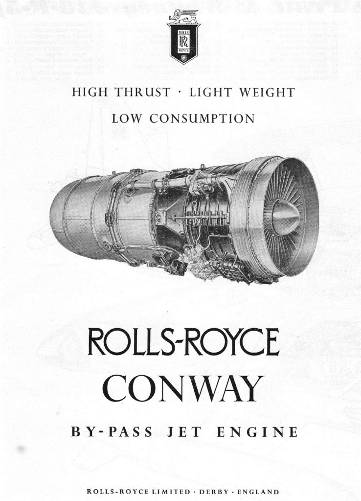
Griffith suggested building a purely experimental design using parts of the Avon and another experimental jet engine, the AJ.25 Tweed. In April 1947 a 5,000-pound-force (22,000 N) design was proposed, but over the next few months it was modified to evolve into a larger 9,250-pound-force (41,100 N) design in response to a need for a new engine to power the Mk.2 low-level version of the Vickers Valiant bomber. A go-ahead to start construction of this larger design was given in October, under the RB.80 name. The Rolls-Royce RB.80 Conway was the first by-pass engine (or turbofan) in the world to enter service. The name “Conway” is an Anglo-Saxon permutation of River Conwy, in Wales, in keeping with Rolls’ use of river names for jet engines.
During development it was decided to further improve the basic design by adding another feature then becoming common, a “two spool” compressor arrangement. Earlier engines generally consisted of a series of compressor stages connected via a shaft to one or more turbine stages, with the burners between them arranged around the shaft. Although this arrangement is mechanically simple, it has the disadvantage of lowering the efficiency of the compressor. Compressor stages run at their maximum efficiency when spinning at a specific speed for any given input air pressure – in a perfect compressor each stage would run at a separate speed. The multi-spool design, first used on the Bristol Olympus turbojet, is a compromise, the compressor is separated into “spools” designed to operate closer to most efficient speed, driven by separate turbines via concentric shafts. Two and three-spool designs are common, beyond that the mechanical complexity is too great.
The new version had a four stage low-pressure compressor driven by a two-stage turbine, and an eight stage high-pressure compressor driven by another two-stage turbine. Now known by the Ministry of Supply designation as the RCo.2, design work was completed in January 1950 and the first example ran for the first time in July 1952 at 10,000 pounds-force (44,000 N) thrust. By this time the low-level Valiant Pathfinder had been abandoned, and so the first example was also destined to be the last. Nevertheless it proved the basic concept sound, and “ran perfectly for the whole of its 133 hours life.”
Conway RC012
The work on the RCo.2 was soon put to good use. In October 1952 the Royal Air Force awarded a contract for the Vickers V-1000, a large jet-powered strategic transport that was intended to allow the V bomber force to be supported in the field through air supply only. Vickers also planned on developing a passenger version of the same basic design as the VC-7. The V-1000 design looked like an enlarged de Havilland Comet, but from the Valiant it took the wing layout and added a compound sweep (a passing vogue in UK design). It also featured the Comet’s wing-embedded engines, demanding an engine with a small cross-section, which limited the amount of bypass the engine could use. It nevertheless required higher power to support a 230,000 pounds (100,000 kg) gross weight, so Rolls responded with the larger RCo.5.
The new engine was similar to the RCo.2 in most ways, differing in details. The low-pressure compressor now had six stages, and the high-pressure nine, driven by two and one stage turbines respectively. The first RCo.5 ran in July 1953, and passed an official type rating in August 1955 at 13,000 pounds-force (58,000 N). Construction of the prototype V-1000 was well underway at Vickers Armstrongs’ Wisley works in the summer of 1955 when the entire project was cancelled. Having second thoughts about the concept of basing the V-bombers away from the UK, the need for the V-1000 became questionable and it became an easy decision to drop the project.
The Conway was saved once again when it was selected to power the Handley Page Victor B.2 variant, replacing the Armstrong Siddeley Sapphire of earlier models. For this role Rolls designed an even larger model, the RCo.8 of 14,500 pounds-force (64,000 N), which ran for the first time in January 1956. However the RCo.8 was skipped over after receiving a request from Trans-Canada Airlines (TCA) to explore a Conway powered Boeing 707 or Douglas DC-8, having interested both companies in the idea. Rolls responded by designing an even larger model of the Conway, the 16,500 pounds-force (73,000 N) RCo.10, and offering the similar military-rated RCo.11 for the Victor. The new engine differed from the RCo.8 in having a new “zeroth stage” at the front of the low-pressure compressor, further increasing cold airflow around the engine. The RCo.10 first flew in an Avro Vulcan on 9 August 1957, followed by the RCo.11 in the Victor on 20 February 1959.
1956
Boeing had calculated that the Conway, even though it had limited bypass in keeping with its original in-wing mounting, would increase the range of the 707-420 by 8% compared to the otherwise identical 707-320 powered by the non-bypass Pratt & Whitney JT4A (J75). In May 1956 TCA ordered Conway-powered DC-8s, followed by additional orders from Alitalia and Canadian Pacific Air Lines, while the Conway powered 707 was ordered by BOAC, Lufthansa, Varig and Air India. RCo.10’s development was so smooth that after delivering a small number for testing, further deliveries switched to the 17,150-pound-force (76,300 N) RCo.12, which was designed, built and tested before the airframes had finished their testing. These models also featured a distinctive scalloped silencer, and a thrust reverser that could provide up to 50% reverse thrust.
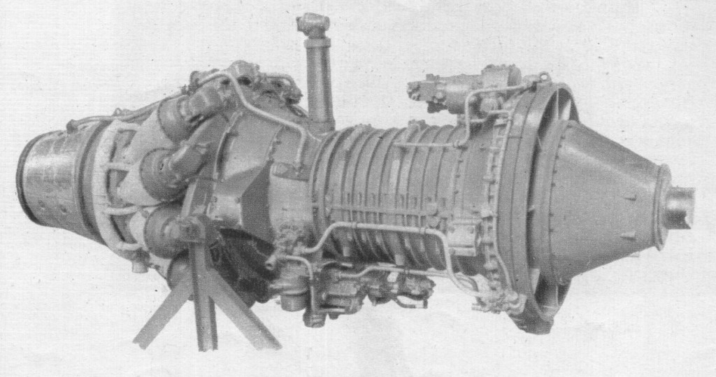
The RCo.12 Conway was an axial-flow turbofan with a low bypass ratio of about 25%. It had a seven-stage low-pressure compressor, the first six stages made of aluminium and the last of titanium. Behind this was the nine-stage high-pressure compressor, the first seven stages of titanium and the last two of steel. The bypass housing duct was also made of titanium. The combustion area consisted of ten cannular flame cans. The high-pressure compressor was driven by a single-stage turbine using hollow air-cooled blades, which was followed by the two-stage turbine powering the low-pressure compressor. Accessories were arranged around the front of the engine, leading to a minimum of increased diameter. The engine produced 17,150 pounds-force (76,300 N) for takeoff, weighed 4,500 pounds (2,000 kg) and had a specific fuel consumption of 0.712 at take-off thrust and 0.87 for cruise.
Although successful in this role, only sixty-nine 707’s and DC-8s were built with the Conway, due largely to the delivery of the first US-built bypass engines, particularly the Pratt & Whitney JT3D. Nevertheless the Conway was successful on these designs, and was the first commercial aero engine to be awarded clearance to operate for periods up to 10,000 hours between major overhaul.
Rolls continued working on the Conway, delivering the RCo.15. This was similar to the earlier RCo.12, but had a larger zeroth-stage along with a larger engine housing to fit it. This improved cruise fuel consumption by 3% while at the same time increasing take-off thrust to 18,500 pounds-force (82,000 N). The designs were otherwise similar, and RCo.12’s could be re-built into RCo.15’s during overhauls.
The final development of the Conway series was the RCo.42, designed specifically for the Vickers VC10. As the need for wing-embedded engines was long abandoned by this point, Rolls dramatically increased the zeroth-stage diameter to increase the bypass from about 25% to 60%, and further increasing thrust to 20,250 pounds-force (90,100 N). First run in March 1961, it would be the most successful of all the Conways, powering all of the VC10 fleet, later models with the RCo.43.
By 1968 a Hyfil carbon-fibre fan assembly was in service on Conways of the VC10s operated by BOAC.
The RB.39 Clyde was Rolls-Royce’s first purpose-designed turboprop engine, first run on 5 August 1945.
The Clyde used a two-spool design, with an axial compressor for the low-pressure section, and a single-sided centrifugal compressor as the high-pressure stage, running on concentric shafts. It had a nine-stage axial compressor and a single-stage centrifugal compressor, in addition to two turbines. The forward (high-pressure) turbine drove the centrifugal blower, and the rear (low-pressure) turbine the axial compressor and contra-rotating airscrews.
The Clyde was the first turboprop to pass its full civil and military type-tests. Its first tests were run at 2,500 s.h.p. and this was later increased to 3,020 s.h.p. Subsequent ratings were 3,500 e.h.p., 4,200 s.h.p. and 4,500 e.h.p.; these last proved that the reduction gear was capable of standing greatly increased overloads.
The Clyde was a long engine with the axial LP compressor in front of what was, in effect, a scaled down Derwent engine. Accessories were grouped around the axial compressor which conveniently narrowed towards the rear. Cooling for turbines and turbine bearings came from a small diffuser on the main shaft as well as tappings from the axial and centrifugal compressors. Testing of the development engines exceeded expectations with the engine soon being rated at 4,030 eshp. One problem un-earthed during testing was that damaging resonances emanated from the straight-cut spur gears in the reduction gearbox.
The 4,030 eshp versions were selected as the main engine of the Westland Wyvern TF Mk.2 strike aircraft.
Despite the promising performance of the test engines Ernest Hives felt that pure-jets were the future and the Clyde programme was terminated with only 9 built, forcing Westlands to use the less than satisfactory Armstrong Siddeley Python on the production Wyverns.
Clyde Type: Twin-spool turboprop Length: 10.1 ft (3.08 m) Diameter: 3.9 ft (1.19 m) Dry weight: 2,800 lb (1,300 kg) Compressor: LP – 9 stage axial, HP – Single centrifugal stage Combustors: Eleven can-type combustion chambers Turbine: HP – single stage axial, LP – single stage axial Fuel type: Kerosene (jet fuel grade) Oil system: Pressure spray scavenge system Maximum thrust: 1,225 lbf (5.45 kN) Overall pressure ratio: 6:1 Specific fuel consumption: 0.71 lb/hp/hr (0.24 kg/kW/hr) Power-to-weight ratio: 1.43 hp/lb (2.08 kW/kg)