Avro Canada CF-100

Avro Canada CF-100 Mk4

The Royal Canadian Air Force, needed an all weather fighter to defend the vast dominion and after talking with the American and British air staffs decided to write its own specification, issued in October 1946. It called for a fighter having a crew of two, advanced radar, all weather and night equipment, heavy gun armament, the ability, to operate from advanced air¬bases with austere ground equipment and runways only 4,000ft long. Plus a combination of speed, rate of climb and range never before attained in any combat aircraft.

Avro Canada CF-100 Article

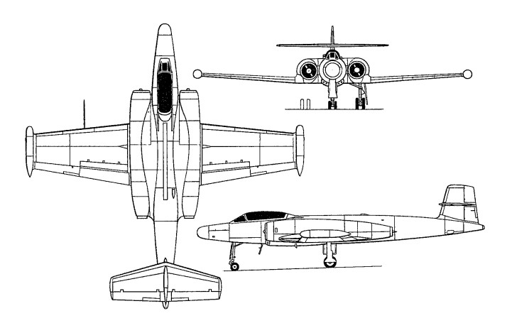
Design of the two-seat all-weather long-range fighter was initiated in October 1946, the Avro Canada team under E. H. Atkin, chief engineer, settled for a long slim fuselage, low unswept wing of quite high aspect ratio, and twin engines on the sides of the fuselage above the wing.
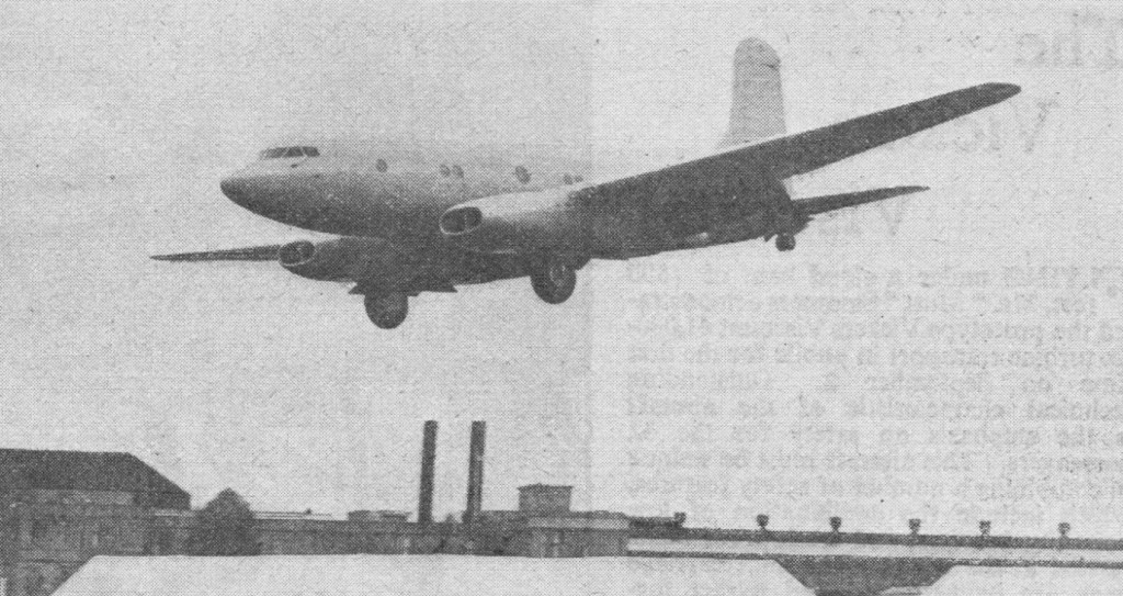
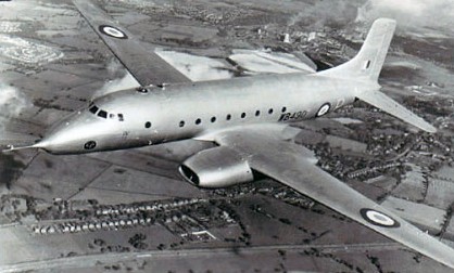
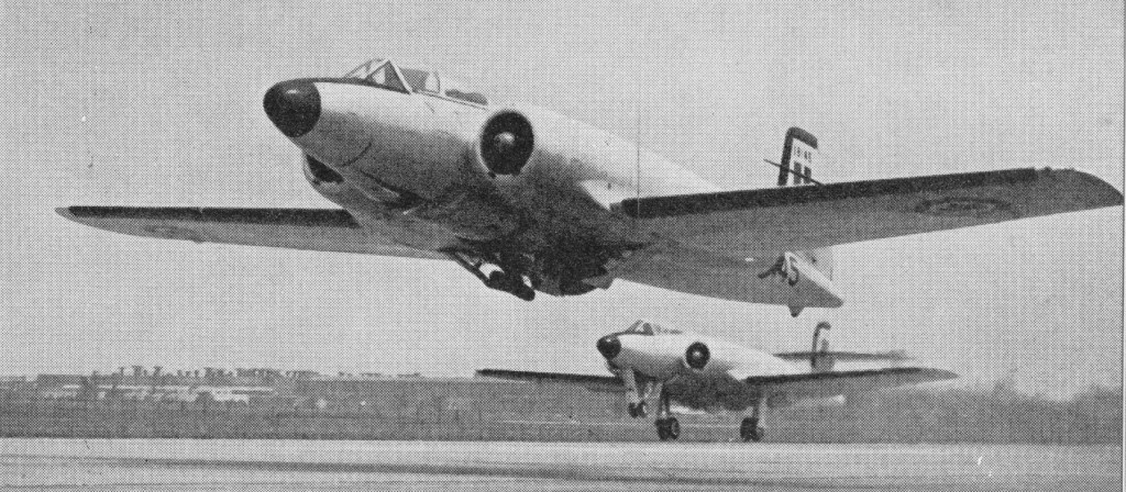
The Avro scheme made the engines higher off the ground, but still easy to service and not difficult to change. The steerable nose gear and main legs all had twin wheels. The first of two prototype CF-100 Mk Is (No 18101, FB-D) was flown on 19 January 1950, both of these aircraft being powered by Rolls-Royce Avon RA 3 turbojets, each of 2948kg thrust. Although not designed for speeds over Mach 0.85, it was taken supersonic during a dive by test pilot Janus Żurakowski in December 1952.

It was a low-wing cantilever monoplane of all metal construction, the tail unit incorporating a tailplane and elevators mounted mid-way up the fin. The retractable tricycle landing gear had twin wheels on each unit, and accommodation for two, in tandem, was in a pressurised cockpit. All control surfaces were fully powered. Large airbrakes were fitted above and below the wing ahead of the flaps. Pilot and navigator sat in tandem Martin Baker seats.

CF-100 Mk.1

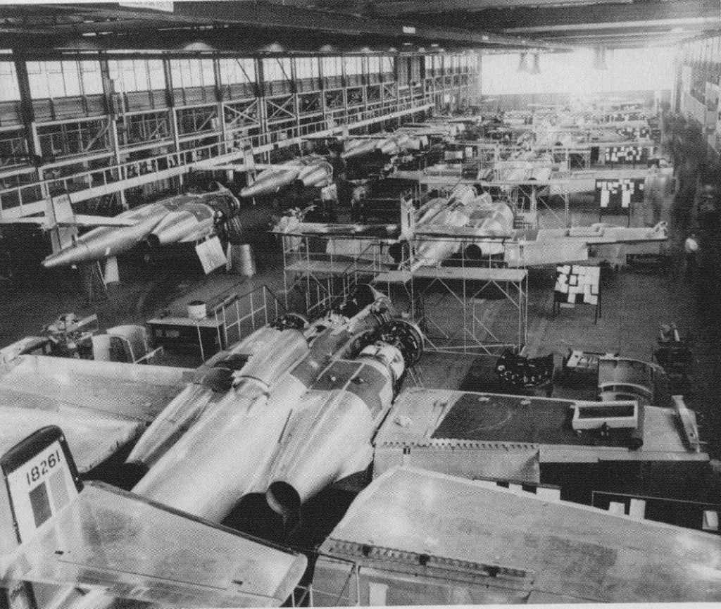
Successful testing of the prototypes led to an order for 10 unarmed pre-production CF-100 Mk 2s, these being the first examples to be powered by 2722kg / 6,000 lb thrust Orenda 2 turbojets, built by the engine division of Avro Canada. When the first of these CF-100 Mk 2s made its maiden flight, on 20 June 1951, it was the first aircraft that had been completely designed and built in Canada. One of this pre-production batch was equipped as a dual-control trainer, becoming designated CF-100 Mk 2T, and another example from this batch was the first to enter service with the RCAF, on 17 October 1951.

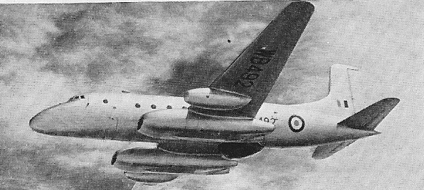
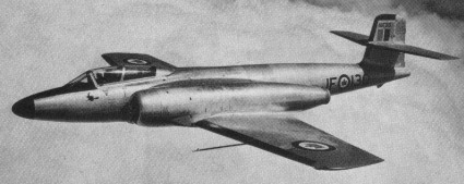
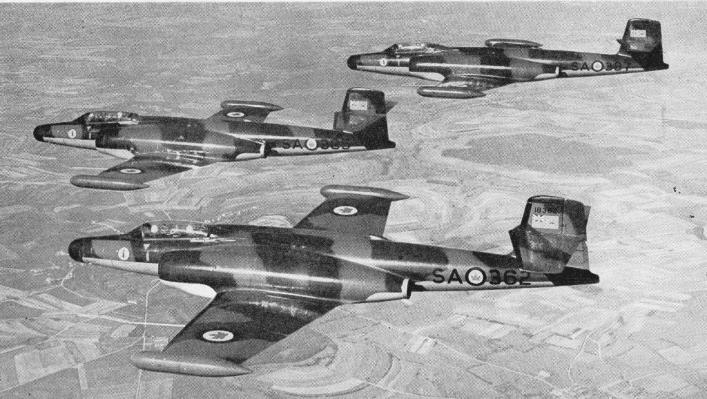
Orders followed for 124 production aircraft designated CF-100 Mk 3 in September 1950, named Canuck by the RCAF, and the first of these entered service soon after a first flight in early September 1952. They differed by having Orenda 8 turbojets of 6,000 lb thrust (of similar output to the Orenda 2s), carried eight 12.7mm Colt-Browning machine-guns in a ventral pack, which could be winched in or out of the fighter as a unit, and were equipped with nose-mounted AN/APC -33 radar. The Mk 3 entered service with No 445 Squadron at North Bay, Ontario, in 1953. A total of 70 of this version was built before production switched to the definitive CF-100 Mk 4, and once the Mk 4 became available in 1954, most of the remaining Mk 3’s were either used at the Operational Training Units or converted to dual control trainers. 50 were converted to CF-100 Mks 3CT and 3DT trainers.

CF-100 Mk.3A

In 1951, in partnership with Hughes Aircraft, Avro Canada completely replanned the CF 100 with the new armament. The tenth CF 100 Mk 2 was chosen as the aircraft to develop the new system, making its maiden flight as the prototype Mk 4 on October 11, 1952, the same day as the first production Mk 3. The nose was longer and fatter, and instead of the APG 33 gunsight radar of the Mk 3 there was a radome for the MG 2 (E4) fire-control radar. The standard Mk 4 retained the gun pack but added wing tip pods each housing either 29 or 30 Mighty Mouse rockets, the same FFAR (folding fin aircraft rocket) of 2.75in calibre as standard on the, USAF interceptors. The Mk 4 had collision course fire control, the new interception method in which the radar and autopilot interlinked to steer the aircraft automatically to launch the rockets in a salvo to pass through a “box” of sky at the same time as the hostile aircraft. It freed interceptors from the need to attack from behind, and in a side on interception gave a much better reflective target for the radar.

The last 54 aircraft were cut from the Mk 3 order, holding production of this model to 70, while orders for the Mk 4 were repeated until they reached the total of 510. It was the RCAFs standard all weather fighter in 1953 59 and continued to serve, into the 1960s after modification to Mk 5 standard. Early Mk 4s were styled Mk.4A and fitted with the Orenda 9 rated at 6,500 lb, and visually distinguished by the free spinning two-blade windmill on the inlet bullet from which alcohol anti icing fluid could be sprayed. The Mk 4B was fitted with the Orenda II of 7,275 lb thrust, and most 4Bs were also fitted with all-rocket armament, the gunpack being replaced by a retractable box containing a further 48 FFARs launched in salvo by hydraulically extending the box briefly into the airstream. A further modification in most 4As and all 4Bs was that the large canopy was blown from a single sheet of Plexiglas.

CF-100 Mk.4B No.445 Sqn RCAF, Marville, France 1957

The first production Mk 4 flew on October 24, 1953. The Mk.4 version was redesignated CF-100 Mk 4A after the introduction of a generally similar CF-100 Mk 4B that differed primarily by having more powerful Orenda 11 turbojets, each of 3300kg thrust.

Unofficially known as the Canuck, the CF-100 Mk 4A was the first CF-l00 to be fitted with AN/APC-40 radar and was powered by the 2948-kg (6,500-lb) thrust Orenda 9 turbojet engine, which was replaced by the slightly more powerful Orenda 11 on the CF-100 Mk 4B model. Armament in both cases took the form of eight 12.7-mm (0.5-in) machine-guns backed-up by 104 70-mm (2.75-in) rockets carried in the distinctive wing-tip pods.
Production of CF-100 Mks 4A and 4B totalled 134 and 144 respectively, being followed by the CF-100 Mk 5 production version.

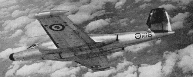
The CF-100 Mk 5, which featured an extended wing span and updated equipment, was lighter for it lack-ed the machine-guns of earlier variants, relying solely on rockets for interception. Aimed entirely at increasing high altitude manoeuvrability, the Mk 5, the first of which flew on October 12, 1955, had just over 3.5ft added on the end of each wing, the new sections having constant chord. Tailplane area was also slightly increased, and among less basic changes was the introduction of a larger wingtip pod housing 52 FFARs, making (with the centreline pack) a maximum of 152. No Mk 5s were built new, the 100 aircraft for inventory being converted while the final 4Bs were still on the assembly line, 53 of which were supplied to Belgium, based at Beauvechain, these being the only CF-100s to be exported.

The first production example flew on 12 October 1955.

CF-100 Mk.5

In addition, a substantial number of CF-100 Mk 4s were up-dated to the later configuration for service with squadrons of the then Royal Canadian Air Force in both Canada and Europe. The CF-100’s operational career as an interceptor came to an end in the early 1960s, but a few aircraft were further modified to act as electronic aggressors in evaluating the performance of Canada’s defences. Known as CF-100 Mk 5C and CF-100 Mk 5D aircraft, these were finally retired by No. 414 Squadron in late 1981.

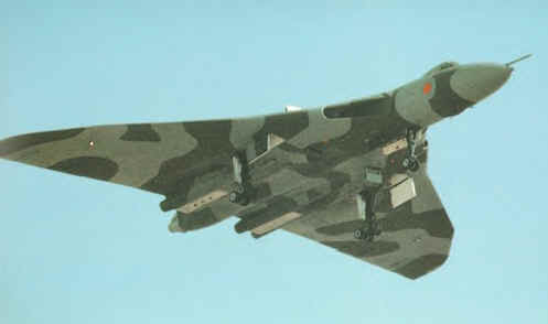
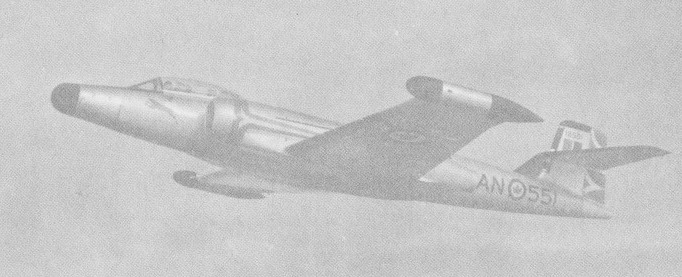
On November 4, 1956, No 445 Squadron brought its Mk 4Bs to Europe to add all¬-weather defence to AAME (Allied Air Forces Central Europe), and until 1962 four RCAF squadrons of 4Bs and 5s operated from the Gros Tenquin/ Marville, / Zweibrücken / Baden Söllin¬gen complex as the all weather com¬ponent of the 1st Air Division. So reliable were the Canadian fighters¬ ¬that the Belgian Air Force purchased 53 ex RCAF Mk 5s and took delivery from December 1957. By this time all CF 100s in front line service had green/grey camouflage, the Belgians merely changing the national markings. Though the added wing sections caused structural problems at high indicated airspeeds the Mk 5 remained an adequate all weather platform well into the 1960s.

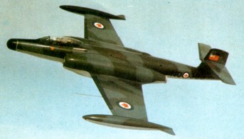
The Avro CF-100 “Canuck” was the RCAF’s second operational jet fighter replacing the de Havilland Vampire. They patrolled the skies over North America and Western Europe from 1953-1981. The aircraft last served with No. 414 “Black Knight” squadron (electronic warfare unit) at North Bay, as a Mark 5D ECM (electronic counter measures aircraft).

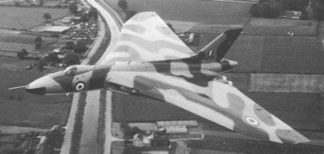
A total of 692 aircraft were produced in the different variants, and the CF-100 was world’s first straight-wing combat aircraft to exceed Mach 1 (in a dive, 18 December 1952). Many innovations in radar and quick-change weapons were developed on the CF-100, and some of its design features were incorporated in the Avro Arrow.

Gallery

A. V. Roe Canada CF-100 Mk.1
All-weather fighter
Engines: 2 x 6,500 lb. thrust Avro Orenda 9 turbojets.
Wingspan: 58 ft 5 in
Length: 54 ft. 4 in
Loaded weight: 34,000 lb.
Max. speed: over 650 m.p.h.
Max. range: 2,000 miles.
Armament: 132x.2.75 in. rockets. In retractable pack under fuselage and wing-tip containers.
Crew: 2

CF-100 Mk 3D dual trainer
Engines: Two Orenda 8, 6000 lb thrust axial flow gas turbine
Maximum speed: Mach .85
Empty weight: 23,000 lb (10 432 kg)
Maximum weight: 34,000 lb (15,436 kg)
Span: 57 ft 6 in (17.5 m) over tip tanks
Length: 52 ft 3 in (15.9 m)
Height: 14 ft 6 in (4.4 m)

CF-100 Mk 4
Engines: 2 x 2948kg thrust Orenda 9

CF-100 Mk 5
Engines: 2 x turbo-jet Orenda 11 or 14, 32.3kN, 3300-kg (7, 275-lb)
Max take-off weight: 16330 kg (36,000 lb)
Empty weight: 10478 kg / 23100 lb
Wingspan: 18.54 m (60 ft 10 in)
Length: 16.48 m / 54 ft 1 in
Height: 4.74 m / 16 ft 7 in
Wing area: 54.9 sq.m / 590.94 sq ft
Wheel track: 10 ft 2 in
Wheelbase: 18 ft 1 in
Maximum speed 1046 km/h (650 mph) at 3050 m (10,000 ft)
Initial climb rate 2591 m (8,500 ft) per minute
Service ceiling: 16460 m / 54000 ft
Range w/max.fuel: 3220 km / 2001 miles
Range w/max.payload: 2072 km / 1288 miles
Combat radius 1046 km (650 miles)
Armament: 29 x 70mm missiles in each of wing containers
Crew: 2

Avro Canada C-102

The design for a 50-seat medium-range civil transport began in 1946 initially proposed with two Rolls-Royce Avon turbojets but by autumn 1947 it was apparent these were not available. The design was modified to take four 3600 Rolls-Royce Derwent 5s.

Avro Canada C-102 Article

With tricycle landing gear, and four turbojets, the prototype was first flown on 10 August 1949, but only six days later was badly damaged through a landing gear failure. It was repaired and flying again within a few weeks, and its four Derwent 5 engines were replaced by two Derwent 8s (starboard outer, port inner) and two Derwent 9s for evaluation. Construction of a second C-102 prototype began, but was not completed.

The C-102 integral fuel tanks have 1375 Imp.Gal inboard and 1025 Imp.Gal outboard giving a total capacity of 2400 Imp.Gal.

Despite an aggressive marketing campaign directed at U.S. airlines and the USAF, the sales prospects of the Jetliner floundered after the launch customer, Trans-Canada Airlines, reneged on a letter of intent in 1948. The company was still attempting to get the CF-100 into production at the time and, consequently, the Canadian government cancelled any further work on the C102 due to Korean War priorities: C. D. Howe demanded the project be stopped to increase production of the CF-100, so the second C102 prototype was scrapped in the plant in 1951, with the first relegated to photographic duties in the Flight Test Department. After a lengthy career as a camera platform and company “hack,” CF-EJD-X was flown for the last time on 23 November 1956 and broken up in 1956, having flown about 425 hours. The nose section now resides in the Canada Aviation Museum in Ottawa.

C-102
Engines: 4 x Rolls-Royce Derwent 5, 1633kg / 3600 lb
Wingspan: 29.90 m / 98 ft 1 in
Wing area: 107.49 sq.m / 1157.01 sq ft
Length: 25.12 m / 82 ft 5 in
Height: 8.06 m / 26 ft 5 in
Take-off weight: 29480 kg / 64993 lb
Empty weight: 16740 kg / 36906 lb
Max. speed: 735 km/h / 457 mph
Cruise speed: 650 km/h / 404 mph
ROC: 1595 fpm
Ceiling: 12285 m / 40300 ft
Range: 2000 km / 1243 miles

Avro Canada VZ-9V Avrocar

The Avrocar was the brainchild of John Frost, an aeronautical engineer at the Malton-Toronto plant of Avro Canada, who conducted studies in the early 1950s on extremely unorthodox vertical-take-off aircraft, beginning with one design that looked like a shovel blade named the “Avro Ace” or “Project Y-1”. and then moving on to saucer-shaped aircraft, originally designated “Project Y-2”. Frost felt that such vehicles could offer vertical take-off capability as well as high-speed forward flight.

The US military became interested, leading to the award of a US Air Force contract in 1955 for experimental development that evolved through various designations such as “Project Silver Bug”, “Weapons System 606A (WS-606A)”, “Research Project 1194”, and so on. The whole project was originally kept a deep secret since it was felt to be a major potential breakthrough. After considering and eliminating a number of different configurations, the effort focused on development of a proof of concept vehicle named the “VZ-9-AV Avrocar” which was funded by both the US Army and US Air Force. It looked very much like an ordinary but greatly scaled-up modern “Frisbee” toy, 5.5 meters in diameter and 1.1 meters thick at the center (18 by 3.5 feet).

There was a fan 1.5 meters (5 feet) in diameter built into a duct in the center, and two little single-seat cockpits with individual clamshell bubble canopies, and powered by three Continental J69 jet engines, which were arranged in the fuselage in a triangle around the central fan. The exhausts of the jet engines drove the fan and were also ducted around the around the edge of the Avrocar to provide lift at low speed. Engine thrust could be redirected to provide forward thrust, with the saucer-shaped airframe acting as a “lifting body”. Differential thrust could be applied at the sides of the VZ 9 for control purposes.

Frost was extremely enthusiastic about the possibilities of his flying-saucer concept, envisioning an “Avrowagon” for family use, an “Avropelican” for naval use, a scaled-up transport version, and a Mach-2 fighter-interceptor version.

A wind-tunnel test model and a flying prototype were built. The test model was sent to the NASA Ames Center in California for wind-tunnel tests. First tethered flight of the flying prototype (58 7055) was at Malton on 29 September 1959, followed by the first untethered flight on 5 December 1959. After some changes to the control system, some forward flights were made just above the runway at Avro’s Malton factory, starting on May 17th, 1961.

The Avrocar was sup¬posed to fly at speeds of over 483 kph (300 mph) at altitude and have a range of 1600 km (1000 miles), but the little saucer never exceeded 30.5 m (100 ft) during trials.

Although Frost and his staff recognized that the Avrocar was inherently unstable and had incorporated an electromechanical stabilization system, it wasn’t up to the job, and once the Avrocar picked itself up to above chest height and got out of ground effect, it bobbled around drunkenly. An improved stabilization system was considered, but Avro was in chaos due to the cancellation of the “CF-105 Arrow” interceptor program. The chaos filtered down to the Avrocar program, and the US backers of the program lost interest. The program was axed in December 1961.

The flight prototype ended up on display at the US Army Transportation Museum. The wind-tunnel test model in the possession of the Smithsonian Air & Space Museum. It remains in storage at the museum’s Garber Restoration & Storage Facility in Maryland.

Avro 707

707C

The initial Air Ministry Vulcan contract called for several forms to be built including two prototypes. Along with this commitment included the construction and delivery of several flight demonstrators. The demonstrators, designated as Type 707, proved an important part of early development of the Vulcan and were produced in five examples – Type 707, Type 707A (2), Type 707B and Type 707C.

Avro 707 Article

The first aircraft made its maiden flight at Boscombe Down on 4 September 1949, but was destroyed later in an accident 26 days later. The accident revealed that the airbrake system had not closed, leading the system to enter a stall and eventually crash – and as no ejection seat system was offered to the test pilot, both man and system were lost in the event.

A new revised design appeared in the Type 707B and flew a year later, this time with an ejection system in a lengthened nose assembly for low-speed research. The Type 707A was used as a high-speed test platform and completed as two examples while a Type 707C existed as well, this becoming a test platform and featuring side-by-side seating, a single vertical tail fin and a straight-wing delta arrangement. The two seat 707C tested power control systems and electronics.

Avro 707C WZ744

In all, testing revealed the aircraft to be extremely agile considering the type and size of the aircraft, no doubt due to the large area delta-wing design choice. These development models eventually gave rise to the Type 698 prototype.

Avro 707
Engine: 1 x Rolls Royce Dervent 5, 1630kg
Take-off weight: 4303 kg / 9487 lb
Wingspan: 10.4 m / 34 ft 1 in
Length: 12.9 m / 42 ft 4 in
Height: 3.53 m / 12 ft 7 in
Crew: 1

707A

707B

707C
Engine: Derwent, 2600 lb
Wingspan: 34 ft 2 in
Length: 42 ft 4 in
Height: 11 ft 7 in
Weight: approx. 10,000 lb
Seats: 2.

Avro 706 Ashton / Tudor 8

Originally titled Tudor 8, modifications to the Tudor airframe needed to produce the test beds were considerable enough to warrant a new name.

The Tudor 8 was first flown on 6 September 1948 when it flew from Woodford to Boscombe Down. The Tudor 8 was demonstrated at Farnborough on 7 September 1948 with four Roll-Royce Nenes of 5000 lb thrust.

Tudor 8 – 7 September 1948

Six Ashtons on order in 1950, which were built for the Ministry of Supply to act as test-beds for research into jet operations.

The first Ashton made its maiden flight on 1 September 1950.

Avro Ashton Article

Powered by four 2270kg Rolls-Royce Nene 5 and 6 engines, the Ashton featured a nosewheel undercarriage which retracted forwards.

Avro 711 Ashton

Four marks of Ashton were built.

Mk.1
High altitude turbojet research
Engines: 4 x Rolls-Royce Nene 5 and 6, 5000 lb
Wingspan: 120 ft
Length: 89 ft 6.5 in
Height: 31 ft 3 in
Loaded weight: 72,000 lb
Max speed: 439 mph
Cruise: 406 mph

Mk.2
High altitude air conditioning tests

Mk.3
Ventral radome and bomb containers outboard of engine nacelles
Bomb sight development
One Mk.3 used as Bristol Olympus testbed

Mk.4
Instrument development

Engines: 4 x 2270kg Rolls-Royce Nene 5 and 6
Take-off weight: 32688 kg / 72065 lb
Wingspan: 36.58 m / 120 ft 0 in
Length: 27.28 m / 90 ft 6 in
Height: 9.53 m / 31 ft 3 in
Wing area: 132.02 sq.m / 1421.05 sq ft
Max. speed: 707 km/h / 439 mph
Cruise speed: 654 km/h / 406 mph

Avro 698 Vulcan

The original Avro 698 Vulcan B1 prototype was developed to Air Ministry Specification B.35/46, issued on 1 January 1947 for Britain to have nuclear bombing capability. The initial design was laid down in 1948 by Roy Chadwick, the technical director of Avro (A.V. Roe and Co. Ltd), and was preceded by the 707 series.

This design featured vertical tail surfaces at the extreme wingtips as opposed to a traditional tail section, offering up a great deal of surface area for improved payload, fuel load and maneuverability. The lack of a true tail section meant that, in some ways, the design was in fact a flying wing. The cockpit was positioned well forward on the fuselage, ahead of the wings and engines, and featured four engines in a staggered internal placement- two engines to a wing. The engines were to be fed by a single large rounded intake. The massive expanse of the wings would have also provided maximum space for internal armament in the form of bomb bays mounted outboard of the dual engine arrangements. Avro designated the new design Type 698 and received the British Air Ministry contract in December of 1947. Along with the Avro design, approval of the Valiant and Victor were also granted, essentially beginning the formation of the V-bomber triangle.

The initial Air Ministry contract called for several forms to be built including two prototypes. Along with this commitment included the construction and delivery of several flight demonstrators. The demonstrators, designated as Type 707, proved an important part of early development of the Vulcan. These development models eventually gave rise to the Type 698 prototype.

Avro Vulcan Article

Flying for the first time on 30 August 1952, the Avro 698 prototype, VX770, had 6,500 lb.s.t. RA3 Avons, subsequent power-plants included the 8,000 lb.s.t. Sapphire, the 10,000 lb.s.t. Olympus 101s and the 20,000 lb.s.t. Olympus 301s. All four engines could be started, flight instruments aligned and powered flying controls run-up within 20 seconds. It had main qears with a total of 16 tyres, and a five seat crew compartment. A single large weapon bay was provided. The first prototype was later lost in a fatal air show accident in September of 1958.

A second prototype powered by four 10,000lb Bristol Siddeley Olympus 101 – with a slightly longer fuselage to eliminate the need for shortening the nose-wheel leg during retraction – made its first flight on 3 September 1953. Both prototypes featured a delta wing with 52 degree sweepback. The second prototype was later fitted with a “kinked” wing design that showcased differing degrees of sweepback separated into different sections of the wing leading edge. The second was later fitted with wings having a redesigned leading edge with compound sweepback and it made its first flight in this form on 5 October 1955.

Wellington, New Zealand 1959

The fuselage itself was streamlined highly, with the cockpit mounted behind a nose cone assembly and just before the wing root intakes and fuselage extending well forward of the wing roots and some distance aft of the wing trailing edge. Fuel was split between either wing and a central fuselage location, all monitored in-flight by a fuel management system. The bomb bay was centrally held in the fuselage and could be fitted with additional fuel for increased range.

The undercarriage consisted of two main landing gears (retracting forward outboard of the engines) and a nose gear positioned behind and underneath the wingroot intakes. Each main gear was fitted with an eight-wheel bogie and retracted forwards while the nose gear and its two wheels retracted backwards. The empennage featured a single large dorsal fin extending from about the midway portion of the fuselage, with the base of the fin extending vertically out from about the extreme end point of the engines. The tail cone housed a drag chute to improve the aircraft’s landing distance.

The Avro Vulcan provided accommodation for five standard crew personnel consisting of the pilot and copilot, a systems operator, a navigator and a radar operator along with additional seating for two more. The pilot and copilot had a view out of the front of the cockpit through a five panel windscreen with framing as well as circular windows to the sides allowing for viewing to the left and right. Ejection seats were afforded to the pilot and co-pilot only – not the entire crew – they would have to bail out.

All production Vulcans were fitted with wings having the revised leading-edge configuration and the first production version was the Vulcan B.1, which entered RAF service in Febru¬ary 1957, powered by Olympus Mk 101 or Olympus Mk 102 engines of 4990 kg (11,000 lb) thrust each. All of these engines were converted later to Olympus Mk 104 standard, up¬rated in stages to 6078 kg (13,400 lb) thrust.

Twenty-five such machines were ordered in 1952 and the first Vulcan squadron became operational in 1957 (this delay in years was caused by yet another fatal accident). B.Mk 1’s were similar to the two prototypes. Early production models were finished the straight delta wings but these were later revised to the kinked wing design. The Mk.1s equipped Nos 83, 101 and 617 Sqn by early 1960. Nos 83 and 101 Sqns were re-equipped with Vulcan 2sband their Mk.1s were taken over by 44 and 61 Sqns.

Farnborough Air Show – September 1958 – 83 Sqn RAF Vulcan B.1

Production models were fitted with an Olympus 101 series engine of 11,000lb thrust (each). This rating was progressively uprated until reaching the Olympus 104 series with 13,500lb thrust. A total of 45 Vulcan B.Mk 1 models were eventually delivered. Re-equipment of three Bomber Command squadrons of the RAF with this version was completed in 1960.

In the late 1950’s, the Vulcan B.Mk 1 had her countermeasures suite revised, becoming the Vulcan B.Mk 1A. Soviet defense technology advanced to the point that operation of the Vulcans in their originally intended mode was now in danger. As such, the aircraft was fitted with chaff dispensers, a tail warning radar (“Red Steer”), a radar warning receiver, and jammers. Twenty-eight B.Mk 1s were converted in this fashion with conversions taking place from 1959 into 1963. B.Mk1A’s and the future B.Mk 2 models were clearly discernable thanks to the addition of the ECM gear in the tail cone.

The Vulcan B.Mk 1 was followed by the Vulcan B.Mk 2 with development beginning in 1955. The system featured a revised and lengthened wing (increased from 99 feet to 111 feet), new Bristol Siddeley Olympus 201 series engines of 17,000lb thrust engines (later production models would feature the Olympus 301 at 22,000lb thrust), updated electrical system, in-flight refueling probe, a reinforced undercarriage (necessitated by the addition of the new engines), the countermeasures suite in the B.Mk 1A upgrade above and overall improvements to the aircrafts performance. First flight of the B.Mk 2 prototype occurred on August 19th, 1958 with deliveries beginning two years later and making up 89 total production examples. The increased performance offered by the Vulcan B2 made it ideal for modification to carry the Blue Steel nuclear stand-off bomb. This weapon allowed the aircraft to launch its attack from outside the immediate missile defences of a target and thereby extended the effectiveness of the Royal Air Force’s airborne deterrent.

This mark entered service in July 1960, and at first remained a high-altitude bomber. By 1961, Vulcan Mk.2s were in service with No.27, 83 and 10 Squadrons. By 1966 these had been withdrawn as the entire force had by that time switched to low level operations using conventional bombs, with a TFR (terrain following radar) on the nose.

Avro Vulcan B.2 Article

Eight B.Mk 2 models were converted to Maritime Radar Reconnaissance platforms (B.Mk 2MRR)) and 6 more were modified as in-flight refueling tankers (K.Mk 2)).

Four Vulcan SR.Mk. 2 reconnaissance aircraft served with No.27 Sqn, and the force was being run down when in April 1982 Argentine forces invaded the Falklands. Several aircraft were converted as tankers in a crash programme by British Aerospace, while others were urgently equipped with bombs, new navigation systems, flight refuelling probes, and underwing pylons for ALQ 101 ECM pods and Shrike anti radar missiles. They bombed Stanley airfield in round trips exceeding 12870km (8000 miles).
The 1964 edition did Jane’s revealed that the Vulcan B2 could cruise at Mach 0.94 at 55,000 feet. Range hi/lo was 2,300 and 1,725 miles respectively.
Vulcans served as engine test-beds for TSR-2 and Concorde.
Production was completed in 1964 and a total of 134 were built at Avro’s Woodford, Cheshire plant, along with the two Type 698 prototypes.
The Vulcan series of bombers saw limited use in combat aggression. Vulcan B.Mk 1 model bombers were sent as an intimidation factor during the Malayan Insurgency. Beyond that, they were used to showcase the types reach to the Soviet Union by conducting regular global flights to and fro. Operations with American forces and other NATO allies were a common occurrence. The only true combat actions including the Vulcan came in the 1982 Falklands War between invader Argentina and responder Britain. Vulcan B.Mk 2 bombers were used in small numbers during the conflict and succeeded in providing Britain with an intimidating force – though actual damage caused to enemy ground forces from Vulcans were minimal. Regardless, the presence of the Vulcan was no doubt on the minds of Argentine ground forces. After the war of 1982, the Vulcan’s career as a dedicated bomber was all but over. Several were converted as an interim measure to fulfill a tanker role gap while the Vickers VC10 airframes were being modified for the job. Six such Vulcan B.Mk 2 models were converted for the role and became the Vulcan K.Mk 2. These Vulcans lasted until 1984 as the VC10s came online.

The last Vulcan squadron was disbanded in March 1984.

On 18 October 2007 Vulcan B.2 XH558 flew from Bruntingthorpe in Leicestershire after a decade long restoration.

Gallery

698 Vulcan Prototype
Engines: 4 x Rolls-Royce RA3 Avon, 6,500 lb.s.t.

Avro Vulcan B Mk.I
Engine: 4 x Bristol Olympus 101, 48952 N / 4990 kg / 11,000 lb
Length: 97.113 ft / 29.6 m
Height: 26.083 ft / 7.95 m
Wingspan: 99.016 ft / 30.18 m
Wing area: 330 sq.m (3,554¬sq ft)
Max take off weight: 170032.0 lb / 77112.0 kg
Max. speed: 556 kts / 1030 km/h
Service ceiling: 55003 ft / 16765 m
Range: 2608 nm / 4830 km
Crew: 5
Armament: 9525 kg Bomb.

Vulcan B.2
Engines: 4 x Bristol Olympus, 17,000 lb.
Wing span: 99 ft 0 in (30.15 m).
Length: 97 ft 1 in (29.61 m).
Height: 26 ft 1 in (7.93 m).
Max level speed: M0.94.

Vulcan B.Mk 2
Engines: 4 x Bristol Siddeley Olympus 301 turbojet, 20,000lbs thrust
Length: 99.90ft (30.45m)
Width: 110.99ft (33.83m)
Height: 27.17ft (8.28m)
Maximum Speed: 646mph (1,040kmh; 562kts)
Maximum Range: 4,598miles (7,400km)
Service Ceiling: 55,003ft (16,765m)
Armament:
21,000 lbs internal
Accommodation: 5
Hardpoints: 0
Empty Weight: 106,000lbs (48,081kg)
Maximum Take-Off Weight: 249,122lbs (113,000kg)

Vulcan B.Mk.2A
Engines: 4 x 9072 kg (20,000 lb) thrust Bristol Siddeley Olympus 301 turbojets.
Max speed: 1043 krn/h (648 mph) at 12190 m (40,000 ft).
Service ceiling: 18290 m (60,000 ft).
Range w/max.fuel: 6400 km / 3977 miles
Empty wt: 45360 kg (100,000 lb).
MTOW: 113400 kg (250,000 lb).
Wing span: 33.83 m (111 ft 11 in).
Length (with probe): 32.16 m (105 ft 6 in).
Height: 8,28 m (27 ft 2 in).
Wing area: 368.27 sq.m (3,964,0 sq.ft).
Crew: 5
Armament: up to 21 454 kg (1,000 lb) bombs; no defensive weapons.

Vulcan B.1

Aviation Industries of Iran Qaher 313

Unveiled on Feb. 2, 2013, the Qaher 313 was no more than a mock-up that will never fly unless it is almost completely redesigned. Iran insists its new home-made stealth fighter aircraft is “not a paper model” but an “aircraft designed by the Islamic Republic for anti-choppers missions.” Furthermore the F-313’s mission would be “protecting security in the Persian Gulf.” This is what a senior Iranian defense ministry official said on Apr. 16.

Addressing a group of Iranian soldiers, Deputy Defense Minister General Majid Bokayee explained that the Qaher 313, designed and developed at a cost of 2 to 3 million USD, has a “unique” structure, will be armed with home-made weapons and equipment and it will feature capabilities that will stun enemies on the battlefield.
According to the Iranian Defense Minister Brigadier General Ahmad Vahidi, the Qaher 313 is an advanced aircraft with a very small Radar Cross Section, capable of taking off from short runways and flying at low altitude like no other most advanced western plane.

The prototype of the Q-313 (or F-313 according to the stencils applied to the aircraft), was presented to President Mahmoud Ahmadinejad and publicly displayed as part of the Ten-Day Dawn ceremonies held in Iran to celebrate the 1979’s victory of the Islamic Revolution.

In the previous days, the Iranian Defense Minister Brigadier General Ahmad Vahidi had said, “The aircraft will be different from the other fighter jets Iran has already made.”

The Q-313 has large, seemingly fixed canards, and little wings whose external section is canted downward.
The canopy material looks like plexiglass or something like that. The cockpit seems to be basic (note the lack of wirings behind the front panel and the presence of few instruments, some of those similar to those equipping small private planes…).

The nose section is so small almost no radar could fit in it. The air intakes are extremely small whereas the engine section lacks any kind of nozzle: engine afterburners could melt the entire jet. The aircraft is way too small, look at the image showing an Iranian officer sitting on the ejection seat in the cockpit.

There is a video allegedly showing the Q-313 in the air. Here it is.

Gallery

Avicopter AC313 / Changhe AC313

The 13.8t AC313 an updated design based on the earlier Harbin Z-8, itself a development of the Aérospatiale Super Frelon. The general designer of AC313 is Mr. Xu Chaoliang (徐朝梁), and the deputy general designer of AC313 is Mr. Li Jiayun (李家云). It is designed to carry 27 passengers, has a reported maximum range of 900 kilometres, and a maximum payload of 13.8 tonnes.

The rotorcraft has already been redesigned once to conform to updated certification standards—the CAAC refused the manufacturer’s application to certify the Z-8 for civil use in 2004. The CAAC determined then that an aircraft certified to military standards in China in the 1970s was not a candidate for civil use now. That appears to have sent the design authority, the China Helicopter Research and Development Institute, back to the drawing board to develop the considerably revised AC313.

The aircraft has new main and tail rotors, and a fuselage using composite material. With three Pratt & Whitney Canada PT6B-67A engines, the AC313 is a single-rotor helicopter with tail rotors, tandem pilot seating, and a non-retractable landing gear. Although based on a 1960s design, the AC313 has been developed to use composite materials for the rotor blade and titanium main rotor. Composite materials are used on 50% of the helicopter and titanium is used for the remainder. The interior comes equipped with a modern integrated digital avionics system and has a cabin height of 1.83 m and 23.5 cu.m in space. In terms of cargo, it can carry up to 4 tonne internally or 5 tonnes on a sling. AC313 is equipped with electronic flight instrument system.

The prototype first flew at Jingdezhen, Jiangxi on 18 March 2010 and made it first public demonstration flight at the Zhuhai Air Show in November 2010.

Built by Avicopter (AVIC Helicopter Company), the AC313 is only the second helicopter to be able to operate in the Qinghai-Tibet Plateau, first being Sikorsky S-70C Black Hawk. The flight testing period for the 13-tonne AC313 was conducted in Hulunbuir City, Inner Mongolia, starting in January 2011 where it was tested to operate in extremely low temperatures as low as minus 46degC marking the scope of Asia’s largest tonnage helicopter meeting the mission requirements of the cold climate and the Earth’s polar regions. The helicopter also set its speed record of 336 km per hour during the testing period. The AC313 became the first China-made aircraft authorized by China’s civil aviation authority in January to fly in high-altitude regions of over 4,500 meters above the sea level.

AC313 has received a Type Certificate issued by the Civil Aviation Administration of China (CAAC).

Following Chinese certification, the first 5 AC313 were to be delivered to Flying Dragon Special Aviation, in 2011. Avicopter has plans to certify the AC313 for sales in Europe and the United States. Xu Chaoliang, the chief designer of the helicopter, said the company has so far received 32 orders from national and international customers.

Like other Chinese aircraft, it has high-altitude operations as a key objective, so that it can fly from bases on the Tibet-Qinghai plateau. The CAAC has certified it to operate from fields as high as 4,500 meters (14,800 ft.).

Equipped with advanced instrument landing system, the helicopter can be used in blizzard weather in plateau regions. It can seat up to 27 passengers and two crew, has a maximum range of 900km (485nm) and is designed for transport, cargo, search and rescue, fire-fighting, offshore exploration and medical evacuation missions, Avicopter says.

CAIH, a wholly owned subsidiary of the China Aviation Industry Corp, was expected to produce 300 helicopters annually by 2015.

Gallery

Avicopter AC301 / AC311 / Changhe AC311

In conjunction with the June certification of the AC311, Avicopter announced orders for 62 of the single-engine, 2.2-ton aircraft from state enterprises, some linked with the manufacturer. The order figure is large for the local market, but it is unclear whether the contracts are binding, since “orders” announced by Chinese manufacturers sometimes do not represent binding contracts, especially when the customer is a state firm.

The AC311 can carry six people and has a 900-kg (2,000-lb.) maximum load capacity, 620-km (385-mi.) range, 4-hr. endurance and 242-kph (150-mph.) maximum cruise speed. “The tips of the main rotor blades are elliptical, improving aerodynamic efficiency and reducing aerodynamic noise,” the manufacturer says.

The rotorcraft is similar to and follows the configuration of the Eurocopter AS350 Squirrel, an unauthorized copy of which Avicopter builds as the AC301. The Chinese company says it has independently developed the AC311 using three-dimensional digital techniques and that it has been designed in accordance with international airworthiness standards. Industry officials say Eurocopter did not help. Honeywell has supplied its LTS101-700D-2 engine for the program, but Turbomeca signed an agreement with Avic unit China South Aviation Industry to cooperate on the Arriel 2B1A for the AC311. Avicopter says the AC311’s dynamic components are designed to be long-lasting, but it gives no figures.

Preliminary design was completed in 2009 and detail design and engineering development in March 2010. First flight occurred the following November. In 2011, the company said it would be certified by the end of that year.

Atlas Aviation Beta XTP-1 / XDM / CSH-2 Rooivalk / Red Hawk / Red Kestrel

Born out of the South African Air Force’s need for an escort and close air support helicopter, the Rooivalk programme was initiated in the early 1980s by Atlas Aviation. The Alpha XH-1 was purely a test-bed for weapon and cockpit systems. It was fitted with a GA-1 Rattler 20mm cannon in a steerable turret, linked to a Kukri helmet-mounted sight. Following on from the Alpha XH-1 research, Denel comimssioned two Puma helicopters to develop the systems required for the Rooivalk. During 1987, the first of two XTP-1 Puma-based test-beds were built and used to evaluate engines, avionics, optronics, weapons and associated control systems for the larger airframe. These test-beds also included the use of locally-produced composite materials used in both airframe and rotor systems.
Puma J1 first flew in 1986 and was the primary avionics, weapons and flight control systems’ test bed.

A highly modified version of the Aérospatiale SA.330 Puma, the XTP-1 has been under development since 1981, and a prototype was revealed in May 1987. Principal upgrades include the installation of an under-fuselage GA-1 20mm cannon turret with a helmet-mounted sight for the gunner and internal ammunition storage, two large stub wings with a total of four pylons for rocket pods, and a redesigned tail unit with a ventral fin and modified horizontal stabiliser.

Puma J2 flew shortly afterwards, its primary task being to develop the weapons systems and integrate them with the aircraft and the other on hoard systems. Concurrently two missile tests were conducted: the first studied the effect of missile blast on the tail boom and the other studied the accuracy of the weapons and associated systems.

The first Rooivalk prototype was unveiled in January 1990 and the second prototype, or advanced design model, flew for the first time in May 1992. It differed from the original experimental design model in having the production 1553B databus and full anti-armour mission equipment fitted. It was also armed with the 20mm cannon fitted in a TC-20 chin turret.

From the J model Pumas the Rooivalk started to take shape in the form of the initial experimental development model (XDM). XDM first flew on 11 February 1990 and began testing aircraft dynamics before progressing on to validate mechanical, aerodynamic and structural design, moving through to expand the flight envelope. It is fitted with an articulated rotor head which allows it to loop, giving it that per¬formance edge over an adversary. Denel also claims that the maximum speed was taken out of the design envelope allowing 196kt in forward flight.

The Rooivalk’s fuselage is mostly metal but with some composites. It has stepped tandem cockpits, with the pilot in the rear and the co-pilot/gunner in the front. The cockpit canopies are formed from flat plate on single curvature sheets to minimise glint from the sun. The twin Topaz turboshaft engines are uprated versions of the Turbomeca Turmo IV and the main rotor is similar to that fitted to the Aerospatiale Puma. An automatic flight control system is fitted, with auto-hover and auto-land. The Rooivalk is designed to operate at low level (under 15m) and at high speeds.

This tandem-seat helicopter is based around a Puma transmission and dynamics and has been built using composite materials. Powered by two Turbomeca Makila turboshafts developing 1175kW it has an all-up-weight of 3245kg. The helicopter can be armed with an assortment of weapons and is capable of operating day or night. Weapons include: 20mm cannon fitted in a TC-20 chin turret or larger DEFA 30mm cannon in a TC-30 chin turret, 2 x 18-tube rocket pods, 2 box launchers for 4 laser beam-riding ZT-35 anti-tank guided missiles, 2 Kukri or Darter Infra-Red homing air-to-air missiles.

The South African Air Force purchased four Rooivalk CHS-2s in 1993 and intend to eventually operate a Squadron of at least 16 Rooivalks. The Rooivalk entered service in late 1996.The Rooivalk was also offered to the British Army to fulfil their Attack Helicopter requirement.

By 1999 was called the Red Hawk.

CSH-2
Engine: 2 x Turbomeca Makila 1A2, 1470kW.
Instant pwr: 1492 kW.
Rotor dia: 15.58 m.
Length with rotors turning: 18.73m
Fuselage length: 16.4m
Height: 4.59m
Empty weight: 5910kg
MTOW: 8750 kg.
Payload: 2030 kg.
Max speed: 167 kt / 309km/h
Max cruise: 150 kt / 278km/h
Max range (internal fuel): 700 km.
Range with max fuel: 705km
Range MTOW with external fuel: 1260km
Service ceiling: 6100m
HIGE: 18,200 ft.
HOGE: 16,500 ft / 5545m
Crew: 2

Engine: 2 x Topaz (Turboméca Makila 1K2), 1794 shp
Rotor diameter: 51.115 ft / 15.58 m
Length: 54.626 ft / 16.65 m
Height: 17.028 ft / 5.19 m
Max take off weight: 19293.8 lb / 8750.0 kg
Weight empty: 13031.6 lb / 5910.0 kg
Max. speed: 167 kt / 309 km/h
Cruising speed: 150 kt / 278 km/h
Initial climb rate: 2198.82 ft/min / 11.17 m/s
Service ceiling: 16503 ft / 5030 m
Maximum range: 680 nm / 1260 km
Range: 378 nm / 700 km
Endurance: 4 h
Crew: 2
Armament: 1x MG 20mm, 8-16 Miss. ext., 4x A/A Miss. V3B Kukri, max. 2030kg