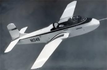
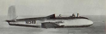
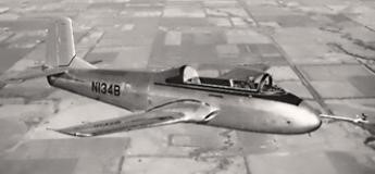
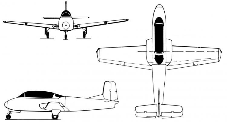
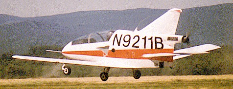
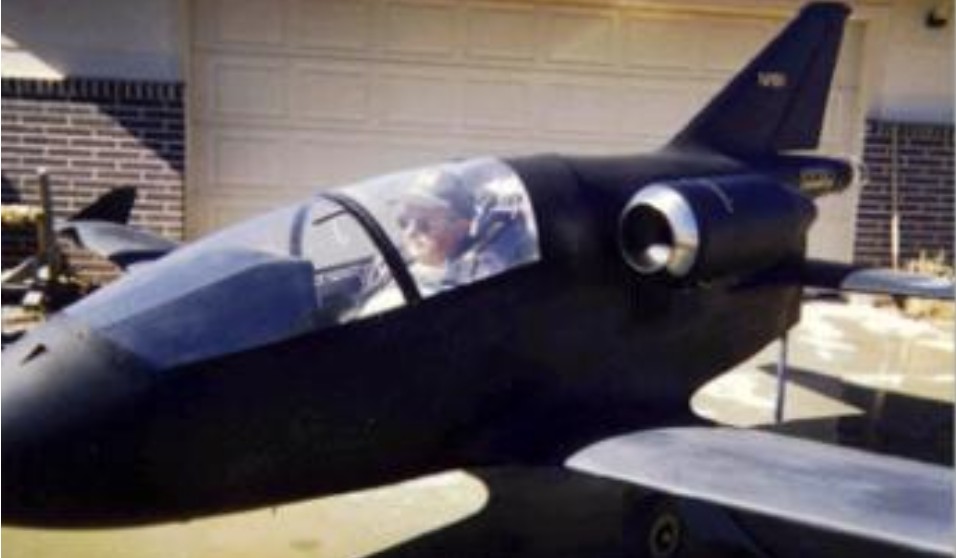
The Model 73 private initiative was inspired by the T34 Mentor and used T-34 parts in the construction of this two-seater jet.
The major differences are a new design of the rear fuselage and the elevation of the stabilizer to clear the engine nozzle. The engine selected was a Continental YT69 T-9 (Marbore II built under license) of 417 Kp thrust.
On December 18, 1955, Beechcraft test pilot Tom Gillespie made the first flight of the Jet Mentor.
The Model 73 was studied by military programs at the time, but never receive any official order. The choice of the U.S. Navy for the Temco TT1 Pinto and the U.S. Air Force in the Cessna T37 meant the final abandonment of the project.
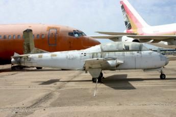
Beech retained the one prototype built during which the test flights continued. Then the plane was stored outside behind a shed.
In the 1960s it was given to a local technical school where it remained for the next 40 years.
Recovered by the Wichita Kansas Aviation Museum, it is stored for many years on an outside car park.
Engine: 1 x Continental YT69 T-9, 417 Kp Wingspan: 9.98 m Length: 9.14 m Height: 2.98 m Wing area: 16.50 m² Empty weight: 1295 kg Loaded weight: 2018 kg / 4521 lb Maximum speed: 463 kph / 253 kt / 295 mph at 15,000 ft Stall: 60 kt Cruise: 395 Km / h Range: 805 km ROC: 1400 fpm
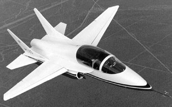
After the BD-5 the Federal Trade Commission banned Bede from accepting aircraft kit investments for a period of 10 years. Shortly after the FTC Consent Decree expired in 1989, Bede revealed plans for a homebuilt tandem-seat supersonic jet, the Bede BD-10. The initial specs for the BD-10 were using a single General Electric J85 engine, the same model as used on the Learjet Model 23, Bede promised customers climb rates of over 12,000 feet per minute, a range of 2,000 miles at 590 mph and max ceiling of around 45,000 feet. Most of all, the BD-10 adverts promised supersonic speeds up to Mach 1.4.
When the BD-10 was announced, it was billed as the world’s first and only supersonic jet kit aircraft. Designed and promoted by Jim Bede, the BD-10 was touted as an everyman’s personal supersonic fighter that could fill the “need for speed” at a relatively low cost.
Construction of the BD-10 is made largely of state-of-the-art honeycomb sandwich aluminum and is designed with all the seriousness of today’s frontline fighter aircraft. The aircraft is complex in structure but not beyond the means of competent builders exhibiting the proper building skills. Build time is around 6,000 hours, and it does take a large amount of change, but in the grand scheme it is a lot less expensive to build and operate than most military surplus jets available to the serious GA pilot.
The prototype was completed in 1992 and began flight-testing. The enthusiasm for the project was huge, but flaws manifested themselves from the BD-10’s very first flight. This didn’t dampen the enthusiasm of aviation publications, and big-name aviation legends such as Bob Hoover and Gene Cernan were hired by the company to pitch the aircraft. But actual performance never matched the optimistic specs. As aircraft weight increased with each design change, range decreased. Even at full thrust, the aircraft couldn’t achieve a speed greater than Mach 0.83.
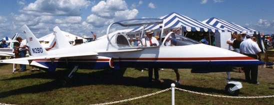
Bede became disenchanted with the project by 1993 as performance of the aircraft continued to disappoint. Mike Van Wagenen, a Vietnam-era fighter pilot and Bede’s primary business partner and inspiration for the BD-10, took the reins of the entire project and pressed ahead. Peregrine Flight International purchased the rights to BD-10 jet from Bede Jet Corporation in 1995, with the redesignated factory-production BD-10 used as the PJ-1 prototype.
The biggest red flag for the project was when wrinkling appeared on the aircraft’s vertical tail after performing demo flights at the 1994 Reno Air Races. The tail was beefed up, and the next prototype, dubbed the PJ-1, was quickly built based on the redesign, and Van Wagenen’s new company, Peregrine Flight International, was born. Rights to the BD-10 jet were purchased from the Bede Jet Corporation in 1995, with redesignated factory-production BD-10 used as PJ-1 prototype (first flown November 1994) and PJ-2 version for certification flying June 1995 with GE J85 as a home-builder kit.
The redesign wasn’t enough. While doing envelope expansion fight testing, on Dec. 30, 1994 (three months after the Reno structural damage), the PJ-1 experienced tail flutter and broke up in flight, killing Van Wagenen. Eight months later, his successor, Joseph Henderson, was killed in the second prototype in Minden, Nevada, when one flap failed to retract on an attempted go-around. After this crash, Peregrine ceased operations. In 1996, Bede sold BD-10 military rights to Monitor Jet in Canada, but the company test pilot refused to fly it, and the aircraft ended up in a museum and was never flown again.
Acquired by Fox Aircraft of Minden, but its president, too, was killed in a crash. In 1996 Monitor Jet Corp of Canada took over but, despite claim of 12 standing orders, no production was forthcoming.
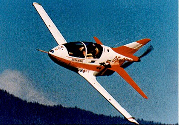
The last kit-built variant of the BD-10 flew in 2003 but suffered an inflight breakup, killing its pilot, Frank Everett, off the coast of Southern California.
In all, five BD-10 variants were built, three crashed, killing each pilot, and two were relegated to static displays.
Later developed into the Vortex Aircraft Company Llc Phoenix Jet-TJ tandem two-seat military primary jet and electronic warfare trainer.
Engine: GE CJ610, 2950 lb thrust. Speed max: 926 mph. Cruise: 620 mph Range: 1840 sm. Stall: 85 mph ROC: 30,000 fpm. Take-off dist: 600 ft Landing dist: 1500 ft. Service ceiling: 45,000 ft Fuel cap: 263 USG. Weight empty: 1580 lbs Gross: 4140 lbs. Height: 8 ft Length: 28.9 ft. Wing span: 21.5 ft Wing area: 98 sq.ft. Seats: 2 Landing gear: retractable nose wheel.
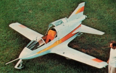
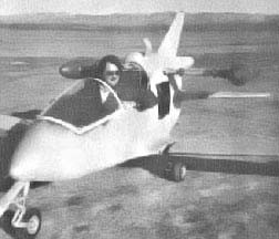
The BD-5 is a high performance single-place, low-wing, pusher-configuration sport plane. Design features include all-metal construction, mechanical retractable landing gear among the industry finest, detachable wings, and wrist action side stick control as in modern day fighter aircraft. Originally developed in the early 1970’s the aircraft was designed to day VFR requirements for use in sport and recreational flying, including limited aerobatic capability. Originally it was powered by a 40-hp Hirth snowmobile engine and was fitted with a wingspan of 14 feet. More recently the wingspan was stretched to 17 feet and the more powerful Xenoah three-cylinder two-stroke engine was installed. The pilot is seated under a transport canopy forward of the engine in a heated cockpit. The landing gear is fully retractable, and the entire fuselage/wing structure is constructed of light alloy materials.
Oshkosh 1973 was the year the BD.5 appeared and it provided a spectacular show in the hands of Les Bervan, Bede’s test pilot. It performed both in long and short winged versions and with a retracting gear. The jet powered BD-5J also made its first public appearance.
BD-5J
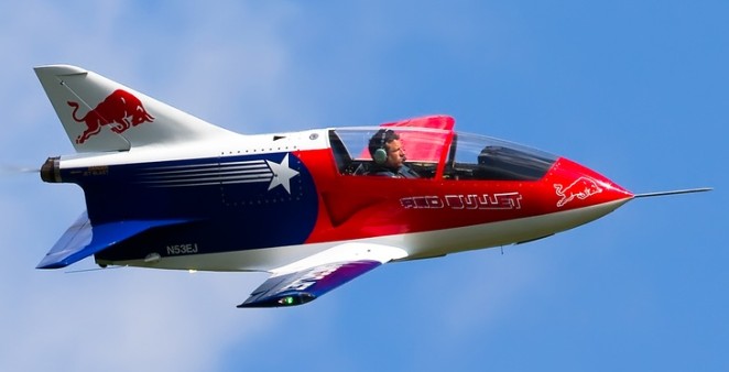
The BD 5J was powered by a 100 kg (202 lb) thrust Microturbo jet engine, spans 5.18 m (17 ft), and is fully aerobatic. After the collapse of Bede, the BD-5 became available as modified conversions such as the Alturair BD-5. BD-Micro Technologies, in late 1995, offered enhanced BD-5 kits. Enhanced BD-5 Kits are designed to be assembled in the shortest time with the least hassle. Components (Wings, Flaps, Ailerons, Vertical Stabilizer, Horizontal Stabilator, Rudder, Fuselage, Landing Gear, and Nose Gear Box) come predrilled on factory jigs. Machined, welded, and difficult to form parts are supplied. The .032” thickness wing skins with modified leading edge improves stall and slow flight control.
Flightline BD-5T Turboprop
The BD-5T Turboprop kit features everything except paint & avionics. With the standard components (Wings, Flaps, Ailerons, Vertical Stabilizer, Horizontal Stabilizers, Rudder, Fuselage and Landing Gear) pre-drilled on factory jigs, and machined, welded, and difficult to form parts are supplied. The BD-5T features a fuselage superstretch of 13.4 in and supplementary wingspar system, detachable wings and control system (20 minutes for assembly or removal), and detachable horizontal stabilizer. Power is from a Quantum H-95 turboshaft engine and Quantum III Propeller. The propeller is developed specifically for turbine engines, weighs 11 lbs including hub and 3 blades. The Quantum turboprop powerplant system (engine & propeller) was designed for the BD-5T. It is a constant speed, torque variable turboshaft engine based on Solar T-62 series components. Flightline Series® BD-5B kit features a complete airframe package- less engine, engine systems, paint & avionics. With the standard Wings, Flaps, Ailerons, Vertical Stabilizer, Horizontal Stabilizers, Rudder, Fuselage and Landing Gear) pre-drilled on factory jigs, and machined, welded, and difficult to form parts supplied, construction time is around 900-1000 hours. Assembled quickly and easily with common skills. Engines can be in the Hirth 2706, Xenoah range.
In 1992, Ed (“Skeeter”) and Richard Karnes started BD Micro Technologies Inc. (BMT), beginning a long journey to update the BD-5 with modern technology while using current building techniques. After many years of research and development, BMT has successfully incorporated many improved design features in an aircraft lineup called the “Flight Line Series” or “FLS” kits.
FLS safety advances include improved stall characteristics, increased pitch stability, reduced airframe fatigue, and modern technology integration focused on increasing systems reliability while reducing pilot workload. Lewis, who formed Lewis & Clark Performance LLC, collaborated with BMT to build the first complete FLS Microjet.
The Flightline Series BD-5J Microjet airframe kit features a complete airframe package requiring 600 to 800 hour construction time. Components (Wings, Flaps, Ailerons, Vertical Stabilizer, Horizontal Stabilizers, Rudder, Fuselage and Landing Gear) are pre-drilled on factory jigs and the fuselage preassembled to “On the Gear” stage. Machined, welded, and difficult to form parts are supplied. Parts are manufactured to aircraft industry standards. The Flightline Series BD-5J Microjet has FLS turbine structural airframe enhancements and a fuselage stretch, 5.2 in. (optional 13.5 in superstretch). The BD-5J has fuel quick disconnects, NACA jet engine intake scoops, Super Spar (supplementary wing spar system), Microjet disc brakes, a Hartwell canopy latch system, and a 5-point safety harness system. With adjustable seating and side stick control, the retractable landing gear cycles in one second. Detachable wings and control system takes 20 minutes for assembly or removal. The horizontal stabilizer is also detachable. The engine is also equipped with an attenuator designed to cut thrust.
BD-5J
Alturair produced a modification of the standard Bede BD-5 to accept an alternative engine.
William ‘Wild Bill’ Brooks Cornville (Arizona) BD-5J Trijet
Bill Brooks flew a BD-5B with a Solar T62, then modified it with 3 HJFS-100 55 Kp units (pod 2 and 1 in the fuselage) and a canard in the front. It is more than probable that he never flew in this configuration.
It was bought by Dave Dearing in 2004 who changed it to standard 5J (the wing is still that of a 5B). Engine side, Dave acquired a Christmas Penny NPT301.
EMG G8-2-130 powered BD-5
Leolan McRorey was the first owner of BD-5 to have equipped it with two Gluhareff EMG G8-2-130 pulse jets. These jets are mounted on a steel rod to each side of the rear fuselage. This configuration was chosen to create a separation between the motors and to avoid the propagation of sound waves.
The small size of the BD-5 managed to board 50 liters of propane in two tanks, a 20 and 30 liter.
Instead of installing a dual throttle, he decided to change the position of the two engines, close to the fuselage.
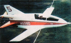
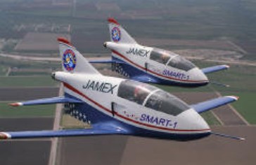
The Freedom Jet, now known as SMART-1, was available only for military shows in conjunction with test and evaluation activities. These aircraft are experimental — research and development category, and were not available for sale to the general public. Renamed as the Small Manned Aerial Radar Target, Model 1 (SMART-1), the tiny jet aircraft that have been performing air shows for the last quarter century have been “drafted” by the military. Its small size, maneuverability, and manned features, plus dependability and economy make the aircraft a threat representative and support system for new system research, design and development. The aircraft is equipped with long range fuel tank, UHF data transmission antenna, TSPI data transmission and recording, and is transportable by road or air cargo.
Thrust – 300 lbs. Wing Span – 17 feet Length – 12 feet Empty Weight – 465 lbs. Gross Weight – 1,150 lbs. Maximum Speed (Sea Level) – 250 knots T.A.S. Minimum (Stall) Speed at Full Gross Weight – 72 knots T.O. Distance – 2,500 feet (S.L.) Maximum Range – 325 n.m. (160 knot economy cruise) Dash Range – 240 n.m. (250 knots) Maximum Operating Altitude – 24,000 feet
Paul Baumgarti was an Austrian who had worked on three helicopter designs during the war years before emigrating to Brazil. He experimented with a number of light helicopters in the 1950s and 1960s including the PB-64 which was an ultra-light single-seater with a minimal tubular fuselage structure.
The PB-64 had a pulse-jet propulsion arrangement with the two 13-kg ITA jets fitted to a transverse stabilising beam set at right angles to the rotor. The aircraft had no tail rotor but was fitted with a small, stainless steel, rudder. The blades have no taper or twist.
No production of any of these designs was undertaken.
Power: 2 x ITA pulse jet, 30 lb thrust Rotor dia: 21 ft 0 in Blade section: NACA 23012 Blade chord: 6.5 in Length: 15 ft 0 in Height: 7 ft 6 in Empty weight: 240 lb MAUW: 700 lb Max speed: 80 mph
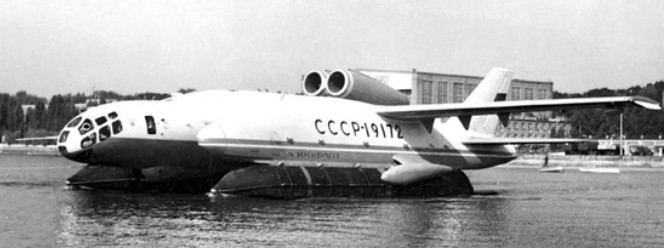
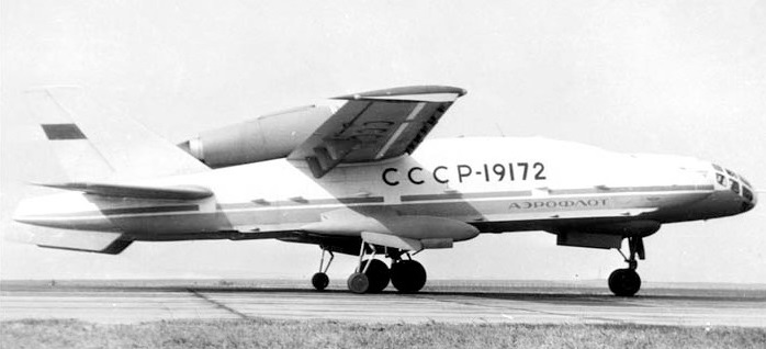
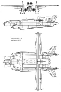
A team led by Roberto Oros di Bartini, a communist who had left fascist Italy for the USSR, presented in 1955 the project of a supersonic flying A-55 medium-range bomber boat. After the comprehensive development and improvement of this project, Bartini approached the creation of an amphibian vertical take-off and landing (SVVP in its Russian acronym).
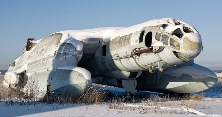
The experimental vertical take-off and landing amphibian VVA-14 (In Russian: ВВА-14) was characterized by the originality of its design and both its size and its take-off weight surpassed all VTOL aircraft built or projected at the time.
The VVA-14 antisubmarine amphibian began to be developed by government resolution in November 1965 at the UVZ helicopter factory (УВЗ – Ухтомскый Вертолетный Завод) and later transferred to Beriev’s OKB in Taganrog which was later would become the Taganrog Aviation Scientific-Technical Complex (TANTK).
In the process of development of the VVA-14 in the UVZ, together with Bartini participated the helicopter manufacturer VI Biriulin and the later general constructor MP Símonov. In the TANTK NA Pogorielov and GS Panatov were added, who would also later become general constructor. The main objective of the project was to develop new aerial means to combat missile-armed submarines, so it was decided, based on the experimental results, to create an amphibious anti-submarine device capable of detecting, tracking and destroying submarines, both on the surface and while submerged. This requirement demanded an autonomy of 4 hours of flight over an area located 500 km from the base. The development of search and rescue missions was established as a secondary objective.
After the analysis, a conceptual scheme based on the SVVP-2500 design was decided. It was a catamaran-like structure with a rectangular centroplane and a central fuselage in which 12 turbojets were located designed to achieve lift force in vertical take-off. Above the centerplane were two two-stage turbojets for horizontal flight. So-called PVPUs (пневматическое взлетно-посадочное устройство – pneumatic equipment for take-off and landing) were used for landing and take-off operations on water. This unusual composition and the great technical difficulties that arose made it necessary to incorporate researchers and engineers from TsAGI into the development., LII, TsIAM, VIAM and NIAT.
It was decided to develop two prototypes: the VVA-14-1M destined to carry out the functional tests of the selected composition in the different operating regimes and the VVA-14-2M to carry out the vertical take-off and landing tests and the processes transition to horizontal flight.
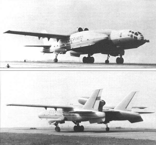
In the late 50s – early 60s, he created the SVVP-2500 vehicle with a take-off weight of 2500 tons in the form of a flying wing with a square center-section and consoles and a power plant made from lifting and cruising engines. In June 1972, the construction of the VVA-14-1M was completed, which did not include the vertical thrust engines and the floats. In July at the TANTK aerodrome, test runs of the prototype began, which was equipped with wheeled landing gear and on September 4 the first flight with pilot Yu took place. M. Kuprianov at the controls and LF Kusnietsov as a navigator. The flight tests that were carried out until June 1975 with a total of 107 flights with a total duration of 103 hours, reaching a maximum speed of 260 km / h.
The VVA-14 was built as a cantilever high wing structure with a supporting centerplane and consoles to which the tailplanes and vertical fins were attached. These cigar-shaped gondolas were designed to contain the PVPU floats. The construction was made fundamentally of aluminum alloys and cadmium steel with anticorrosive coating in attention to the marine operation.
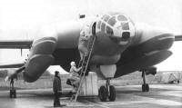
The fuselage was of semi-monocoque construction and was fused with the centroplane to achieve a supporting fuselage. In the bow was located the cockpit for a crew of three. This cabin could be detached from the fuselage in an emergency and ensured the life of the crew without the need for ejection seats.
Behind the cockpit was located the lift engine module consisting of 12 Kolosov RD-36-35PR (РД-36-35PR) turbojets and the weapons bay.
The wing was composed of the rectangular-shaped centroplane and the outer sections called OChK of trapezoidal shape with a positive dihedral of 2º. These sections featured flaps along the entire trailing edge, ailerons and flaps.
The tail planes were of the cantilever type with a sag of 40º at the leading edge and a surface area of 21.8 m². The elevator had an area of 6.33 m². The two vertical surfaces had a total area of 22.75 m² with a sag of 54º. The area of the rudders was 6.75 m².
The PVPUs (Pneumatic Takeoff and Landing Equipment) were made up of floats 14 meters long, 2.5 meters in diameter and a volume of 50 m3 made up of 12 sections. For its extension and retraction, a complex mechanical-hydro-pneumatic-electric system was used with 12 cylindrical injectors (one for each section). The air for filling was supplied by the compressors of the driving engines. A retractable tricycle landing gear was designed to transport the aircraft over land, with the front landing gear fixed to the fuselage and the main landing gear located on the inner surface of the nacelles. Each undercarriage mounted two wheels.
The combined powerplant consisted of two Soloviov D-30M double-contour turbojets with a thrust of 6800 kg for horizontal flight, located next to each other on separate consoles on the rear of the centerplane and 12 Kolosov RD-36 ascending turbojets. 35PR of 4400 kg each located in pairs with a certain forward inclination in the space of the fuselage behind the cockpit. At the top, an upward opening hatch for each pair of engines covered the air intakes. At the bottom were the nozzles with an adjustable angle of incidence. The use of an auxiliary turbocharged engine was assessed during the project.
The fuel system consisted of 14 tanks for a total capacity of 15,500 liters. A refuelling system at sea was devised.
The steering system of the aerodynamic surfaces was conventional, but in the case of vertical operations and the regime of transition to horizontal flight, 12 additional levers operated in pairs were conceived that allowed the control of the compressed air of the lift engines. The autopilot system allowed course control in all flight regimes.
The flight surfaces had a hot air anti-freeze system and the engines had a fire protection system.
The crew cabin had an oxygen and air conditioning system. An automatic stabilization system was designed to be used during vertical take-off and landing operations and horizontal flight in adverse weather conditions. In the search and rescue version, the VVA-14 was also designed with radio marking systems. The antisubmarine version had to use a Burevietnik search system capable of locating enemy submarines and coordinating the data necessary for their destruction. To detect the submarines, it was planned to equip the VVA-14 with 144 RGB-1U hydroacoustic buoys (РГБ-1У) and up to 100 noise generators, in addition to a Bor-1 magnetic anomaly detector. (Бор-1).
The armament for the antisubmarine version would be located in a hold in the fuselage with a capacity for 2000 kg, being able to incorporate two naval torpedoes or eight IGMD-500 aviation mines (ИГМД-500) or 16 PLAB-250 aviation bombs (ПЛАБ-250). The use of a survival system equipped with active and passive interference launchers was also designed.
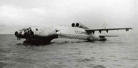
In 1974 they settled the VVA-14-1M the PVPU developed at the Bureau of Construction Aggregates of Dolgoprudniencsky and produced in Yaroslavsk, with two large inflatable floats deployed at the bottom of the gondolas. The tests began on June 11, 1975 and included the inflation and collection of the PVPU, which showed that the operation was quite complex and the solution still had to be worked on.
Between 1974 and 1975, 106 cycles of expansion and collection of the PVPU were carried out of which 11 were carried out in flight, both from the water and from the ground.
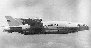
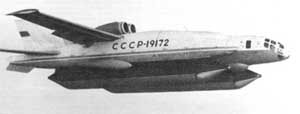
VVA-14 in flight with floats
Flight tests confirmed the calculations and showed that at the bottom of the 10.75-meter chord centroplane an effective air cushion was formed at 10 – 12 meters high during landing and at 8 meters the cushion was so dense that test pilot Yu. M. Kuprianov on more than one occasion asked to be allowed to release the controls so that the machine would settle on its own.
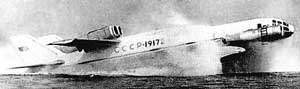
VVA-14 in flight with the floats extended.
The VVA-14 never made the vertical take-off and landing. The engines for this purpose were never ready. The VVA-14-1M was modified with the installation in the bow of two Soloviov D-30M engines destined to blow and create the air cushion under the centerplane, using the aircraft as an ekranoplane. Among the main modifications made, the inflatable floats were replaced by metallic ones. This model received the designation 14M-1P and was successfully tested in 1976 on the Taganrog peninsula in the Sea of Azov.
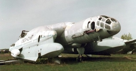
Today the remains of this project are preserved in the VVS Museum of Mónino.
VVA-14 Powerplant: two Soloviov D-30M double-contour turbojets, 6,800 kg and 12 Kolosov RD-36-35PR, 4,400 kg Wingspan: 30.00 m Wing area: 21.77 m² Length: 25.97 m Height: 6.79 m Empty weight: 35356 kg Maximum takeoff weight: 52,000 kg Fuel weight: 14000 kg Normal military load: 2000 kg Maximum military load: 4000 kg Maximum speed: 760km / h Cruising speed: 640 km / h Patrol speed: 360 km / h Practical range: 2450 km Practical ceiling: 8000-10000 m Armament: 2 x naval torpedoes / 8 x IGMD-500 aviation mines (ИГМД-500) or 16 PLAB-250 bombs (ПЛАБ-250) Accommodation: 3 crew
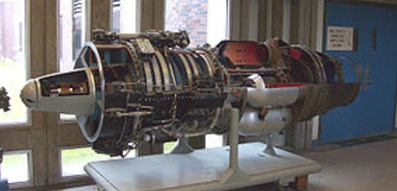
The Avro Canada TR.5 Orenda was the first production jet engine from Avro Canada’s Gas Turbine Division. Similar to other early jet engines in design, the Orenda outperformed its rivals in most ways, and the Orenda-powered Canadair Sabres were among the fastest of all first-generation jet fighters. Over 4,000 Orendas of various marks were delivered during the 1950s, Avro’s greatest engine success.
The Orenda design started in the summer of 1946 when the Royal Canadian Air Force (RCAF) placed an order with Avro Canada for a new night/all-weather fighter. To power the design, Avro decided to build their own engines. Avro had recently purchased Turbo Research, a former crown corporation set up in Leaside, Toronto, to develop jet engines.
Turbo Research was in the midst of designing their first engine, the 3,000 lbf (13 kN) TR.4 Chinook, which could easily be scaled up for the new fighter design. It was decided to continue working on the Chinook to gain experience even though they had no intention of producing it.
As work on the Chinook continued, Avro’s newly christened Gas Turbine Division started work on the larger 6,000 lbf (27 kN) thrust design needed for the RCAF contract. Winnett Boyd started detailed design in autumn 1946, and a formal contract was received in April 1947. The only major change was the addition of a tenth compressor stage of stainless steel, and changing the third stage from aluminum to steel as well. The design work was completed on 15 January 1948, just prior to the first run of the Chinook on 17 March 1948. During the design Joseph Lucas of the UK was contracted to help with the combustion design, which led to a slight delay as they recommended using a longer combustion chamber than originally designed. The resulting TR-5 was named “Orenda”, an Iroquois word meaning “Tribal Soul on the Right Path”.
Given the experience of the Chinook, and the fact that the two designs were similar in many ways, progress on the Orenda was rapid. Parts started arriving in 1948, and the first engine was completed and run for the first time on 8 February 1949. Avro was so confident of the design that they invited high-ranking officials from the RCAF and Canadian government to witness this very first test, which went off without a hitch after fixing a minor electrical problem. Within two months the engine had already passed 100 hours of running time, and on 10 May had reached its design thrust of 6,000 lbf (27 kN). At the time, it was the most powerful jet engine in the world, although it held this record only briefly until the Rolls Royce Avon RA.3 was introduced the next year.
By 1 July it had passed 500 hours, and had run for 477 of these before requiring a rebuild. In September it was on its way to 1,000 hours when a technician’s lab coat was sucked into the engine, complete with a set of razor blades in his pocket. From then on testing was carried out with a set of metal rings in the intake to avoid ingesting foreign objects. After repairing the damage the engine returned to testing, now joined by two further examples of the Orenda 1. Together they passed a total of 2,000 hours by 10 February 1950. By this point a problem with fatigue cracks in the seventh and eighth stages had become apparent, which required them to be redesigned and made much thicker. This solved the problem, and by July they had passed 3,000 hours.
Flight testing started with a converted Avro Lancaster, FM209, one of the many Mk.10’s built at the Victory Aircraft plants during the war. The two outboard Merlin engines were replaced with the Orendas, and the new aircraft took to the sky on 10 July. Avro test pilots had much fun flying the aircraft across Lake Ontario to the Buffalo, New York area, where they were able to easily outperform the P-47 Thunderbolt’s of the Air National Guard that were sent to investigate. In one incident at an airshow, all four engines were turned off by mistake, but the Orenda’s quick start time allowed them to recover. The aircraft ran up 500 hours by July 1954, when this portion of flight testing ended; it was destroyed in a hangar fire on 24 July 1956.
The Orenda 2 was the first production model, passing its qualification tests in February 1952. This version showed additional cracking in the ninth stage, and had to be strengthened like the earlier model. Even before being qualified, the engine had been fitted to the Avro CF-100 and flown on 20 June 1952, with a squadron of pre-production Mk.2 aircraft entering RCAF service on 17 October. The Orenda 3 was similar, but had a number of modifications to allow it to be mounted in the Sabre in place of the J47. One example was produced and sent to North American Aviation.
The first real production model was the Orenda 8, which was the powerplant of the CF-100 Mk.3. This model was first flown in September 1952 and entered service in 1953. This was soon followed by the Orenda 9 powered Mk.4 that flew on 11 October 1952, and then by the rocket-armed Mk.4A with the 7,400 lbf (33 kN) Orenda 11. The Orenda 11 demanded higher airflow through the engine, and featured a second turbine stage to power the more powerful compressor. The 11 would be the primary production version for the CF-100, powering the Mk.4A and all future versions, with over 1,000 engines produced.
While work on the CF-100 continued the RCAF also started looking at a new day fighter, eventually selecting the Sabre. A single Sabre 3 was built with the Orenda 4 engine, with performance similar to the US models. Production then turned to the Sabre 5 with the Orenda 18, and then to the Sabre 6 with the Orenda 11-derived 7,275 lbf (32,360 N) thrust Orenda 14. The resulting Sabre was both lighter and more powerful than its J47 powered counterparts, and went on to set a number of air speed records. Most notable among these was Jacqueline Cochran’s supersonic flight in the sole Sabre 3, which Canadair lent to her for the effort. Canadair built 1,815 Sabres in total, 937 of these equipped with Orendas. Several examples, notably one at Boeing, serving into the 1970s.
The engine was so successful that the Gas Turbine Division was renamed Orenda Engines when Hawker Siddeley reorganized their Canadian operations in 1955.
The Orenda was fairly conventional in layout, built in three main parts; compressor, combustion area, and turbine/exhaust.
At the front was the compressor section, containing the ten-stage compressor housed in a tapering magnesium alloy shell. The shell was machined with grooves that held the stators. At the front of the compressor was an intake fairing with a prominent “nose cone” containing the front main bearing. Four guide vanes held the cone in place, with a power takeoff shaft running inside one of them to power the top-mounted accessories section. The nose cone also held the electric starter motor, which acted as a generator once the engine was up and running. The engines used on the CF-100 also contained a uniquely Canadian invention, two prominent winglettes at the very front that sprayed alcohol into the intake as a de-icing system. The CF-100 versions also mounted the debris cage, mentioned earlier.
The compressor had ten axial stages of mixed steel and aluminum construction. In the original Orenda 8, 9 and 10’s this operated at a 5.5:1 compression ratio, compared to about 3.5 for wartime designs. The hub consisted of three aluminum disks carrying the first nine stages, and a steel disk bolted onto the end carrying the tenth. The central casing held the power shaft and was made from magnesium alloy. Around it were the six flame cans. The turbine was made of solid Inconel blades attached to an austenitic steel hub. The blades were air cooled by bleeding off compressed air from the fifth compressor stage and piping it to the turbine face, the six pipes lying between the flame cans. The exhaust section consisted of welded steel sheeting.
Variants: Orenda 1 – original prototype models, 6,000 lbf (27 kN) Orenda 2 – first production model Orenda 8 – improved reliability, 6,000 lbf (27 kN) Orenda 9 – improved thrust, 6,500 lbf (29 kN), required some changes to the nacelles Orenda 10 – Orenda 9 adapted for the Sabre Orenda 11 – main production version for the CF-100, 7,400 lbf (33 kN) Orenda 14 – similar to the 11, 7,275 lbf (32.36 kN), used on both the CF-100 and Sabre Orenda 17 – combined the compressor from the 9 with the turbine of the 11, along with an afterburner 8,490 lbf (37.8 kN) wet
Specifications:
Orenda 9 Type: Turbojet Length: 10 ft 1 in (3.07 m) Diameter: 3 ft 6 in (1.07 m) Dry weight: 2,650 lb (1,200 kg) Compressor: 10-stage axial flow Combustors: can type, 6 Fuel type: Kerosene Maximum thrust: 6,500 lbf (29,000 N) at 7,800 rpm
The Avro Canada TR.4 Chinook was Canada’s first turbojet engine, designed by Turbo Research and manufactured by A.V. Roe Canada Ltd. Named for the warm Chinook wind that blows in the Rocky Mountains, only three Chinooks were built and none were used operationally. The Chinook was a successful design in terms of introducing new concepts and materials, and after being scaled up from 2,600 lbf (12 kN) to 6,500 lbf (29 kN), would go on to become the Orenda.
In late 1942 the National Research Council of Canada (NRC) sent Dr. J.J. Greene and Malcolm Kuhring to England to report on the various advanced research projects and to see if Canada could play a role in them. One of the team’s many topics in the resulting report was an introduction to the work on jet engines being carried out by Frank Whittle at Power Jets. The Department of Munitions and Supply (DMS) thought this was a wonderful opportunity to get in at the “ground floor” of a newly developing field, one that the country could enter with relative ease and thereby reduce their dependence on foreign suppliers for aircraft engines.
In early 1943 a new mission, including Dr. Ken Tupper and Paul Dilworth from the NRC and C.A. Banks of the DMS, left for England specifically to study the jet engine and report on ways that Canada could contribute to the jet effort. The resulting report, known today as the Banks Report, suggested two lines of research. One led from the realization that no one in the nascent industry really understood the effects of real-world weather on the operations of jet engines, especially in icing conditions. The report suggested forming a research center specifically to study this problem. The report went on to suggest the formation of a private jet engine company.
Almost immediately after they returned to Canada, Dilworth started work on what became the Cold Weather Testing Station in Winnipeg. They were supplied with an original Whittle W.1, and later a captured Junkers Jumo 004. Their research demonstrated that water ingestion reduced power by about 20%, not entirely unexpected, but at the same time doubled fuel use, which was a surprise. Further work on the problem led to a number of design elements that would be used on future Canadian jet designs.
While the CWTS was being set up, the government also worked on the second part of the Banks Report, and on 1 July 1944 formally incorporated Turbo Research in Leaside, Toronto. Dilworth returned from CWTS to lead a series of design studies based on the Whittle-style centrifugal compressor design, known as TR-1, TR-2 and TR-3. However, these designs were abandoned in favor of a new axial compressor-based design, the TR.4, likely due to their exposure to the Jumo 004. Over the next year the team was built out as more engineers joined the effort, including Winnett Boyd, Joe Purvis, Burt Avery and Harry Keast from Power Jets. Detailed design was completed in early 1947, and the engine first ran on 17 March 1948.
At the time the Chinook was being designed, Avro had little production capacity and no engine fabrication experience. They farmed out parts manufacture to 1,200 different companies, providing everything from gears and ball bearings, to the compressor and turbine blades. Many of the techniques for fabrication had never been needed in Canada before, and led to a small industrial revolution as they were developed for the project. Among the many advances brought to Canadian industry as part of the Chinook program, Light Alloys Ltd. invested in their first aluminum casting, while Shawinigan Chemicals did the same for stainless steels.
Although the team had already turned to the design of the Chinook’s successor, the Orenda, work on the engines continued in order to gain experience in construction and operation. Frank Whittle personally viewed the engine in 1948. Only six sets of engine parts were made, from these three complete engines and one compressor section were completed. By October 1949 the engines had run over 1,000 hours and had improved to over 3,000 lbf (1,360 kg) thrust.
Designing on the basis of a theoretical twin-engine fighter aircraft, seemingly similar to the Messerschmitt Me 262, the TR-4 design was in many ways an analog of the Jumo 004. The primary difference in design was the use of six separate flame cans instead of the singular annular combustor of the Jumo. Compared to the Jumo the Chinook was smaller and lighter; it was about the same diameter, 20 inches shorter, and over 300 lb (140 kg) lighter. In spite of this it produced almost double the thrust, largely due to the improved materials, especially in the turbine, which allowed for higher operating temperatures.
The Chinook’s compressor consisted of nine axial stages. The first two were made of stainless steel to help with debris but the remaining seven stages were made of aluminum alloy. These were attached to hubs that were also primarily made of aluminum, except the ninth disk, which was steel. Behind the compressor were the six straight-through flame cans, exiting onto a single-stage steel turbine. The final exhaust gas temperature was 650 degrees Celsius. Air cooling for the turbine was provided by a series of six tubes running from the middle of the compressor to the turbine, lying between the flame cans, which exited in front of the turbine face. An accessories section was powered off a shaft at the front of the engine at the main bearing. The front main bearing was located under a prominent nose cone that extended well out in front of the engine. An oil tank was “wrapped” around the engine at about the 4 o’clock position, as viewed from the front.
Specifications Type: Turbojet Length: 10 ft 10.5 in (3.3 m) Diameter: 2 ft 8 in (81 cm) Dry weight: 1,250 lb (570 kg) Compressor: Axial flow
The first stages of development of a new two-seat all-weather long-range interceptor for the RCAF began in early 1953, at the time when the RCAF was busy forming its first CF-100 squadron. By April 1954 Avro’s design team was involved in the manufacture of the first five Arrow 1 prototypes.
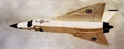
The CF-105 featured a true delta-wing design fitted with twin turbojet engines. The aircraft would be piloted by a crew of two, made up of a pilot and his radar operator. Avro made the decision to design the CF-105 as a pure delta wing platform. The aircraft’s single-minded interceptor purpose was to travel in straight lines, finding the fastest way to get to its target in the shortest amount of time. The increase in drag was offset by the added fuel that could be stored in the wings as the CF-105 system would be expected to feed two thirsty turbojet engines, each with afterburner capability. The Orenda Iroquois – a highly advanced engine for its time – was selected as the powerplant that would propel the CF-105 Arrow for decades to come. This had a needle-nose, widening just aft of the cockpit, where intakes on each side of the fuselage fed air to two turbojet engines mounted side by side within the fuselage. The Arrow 1s were powered by two Pratt & Whitney J75s, but it was intended that the following Arrow 2s would have engines of indigenous design and manufacture, in the form of PS-13 Iroquois turbojets, developed by Avro’s Orenda engine division, each of which promised a thrust of 12700kg with maximum reheat.
The two-man cockpit was held well-forward in the design, protruding between the two rectangular intakes to either side. The intakes ran the length of the fuselage and the delta wings extended from the installations as high shoulder-mounted assemblies. The aircraft’s layout ended with the twin engine outtakes at rear capped by a single vertical tail fin set between the two engine compartments. The main landing gear extended from the wings (another benefit of the delta wing concept) as opposed to the fuselage body with two wheels to a gear (in single file arrangement). The nose landing gear leg retracted into the fuselage just behind and below the cockpit.
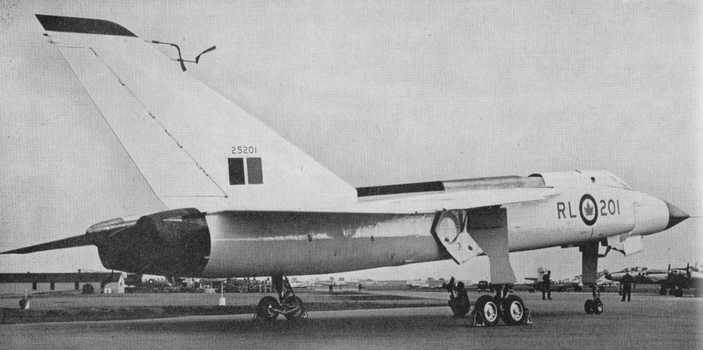
The Arrow appeared in its first form as the Mark 1 with production approved by 1955. The first Arrow completed October 1957, became model RL-201 and this aircraft was fitted with lower-powered Pratt & Whitney J75 series engines while the Orenda brand series were completing development. The unveiling was intended to be a huge affair but the successful launch of the Soviet satellite Sputnik destroyed any hope of that and in many ways forecasted the future of the CF-105 program itself. Several other delays of the internal systems added to the already bumpy curtain-raising event.
The Royal Canadian Mounted Police were monitoring an illegal agent working for the Russians on the Avro Arrow project.
The first was first flown by Jan Zurakowski on 25 March 1958, this Mach 2 all weather fighter had a continental radius of action and could operate up to 70,000ft. It achieved 1,000 mph on its seventh flight. The two underfuselage speed brakes could be held open during Mach 1 flights. Four more Mark 1 soon followed. Over the months of testing, a major issue arose with the complex main landing gear arrangement. The design relied upon the two main single-file landing gear wheels to fit into the wing. This necessitated that the gear rotate before settling fully into the thin delta wing design. After addressing several of these key issues, the five CF-105’s were moved out of the A.V. Roe internal company test program and forwarded to official military trials beginning 1959.
By this time, the future of the CF-105 was already highly in doubt. 1957 saw a political turn in Canada which the new conservative-leaning party began targeting the spending projects of the former liberal party. The CF-105 was not immune to the discourse and when the Americans came calling with their NORAD (NORth American Air Defense) initiative and its thousands of available aircraft for use across Canadian air defense. It was seen fit to cancel the CF-105 Arrow project altogether on 20 February 1959 by John Diefenbaker, a Prime Minister of Canada, after expenditure of about $400 million. It is estimated that an astounding 50,000 jobs were lost with the cancellation of the program – or about 80% of Avro Canada altogether – permanently damaging the Canadian aerospace industry.
The prototype and six more airframes were sliced up, crushed and burned. Three years later Canada had to buy McDonnell F-101 Voodoo fighters from the USA.
Engines: 2 x Pratt & Whitney J75-P-3, 47,000lbs thrust. Wingspan: 15.24 m / 50 ft 0 in Length: 23.72 m / 78 ft 10 in Height: 6.48 m / 21 ft 3 in Wing area: 113.8 sq.m / 1224.93 sq ft Empty Weight: 49,042lbs (22,245kg) Maximum Take-Off Weight: 68,608lbs (31,120kg) Maximum Speed: 1,307mph (2,104kmh; 1,136kts; M 2.3) Maximum Range: 410miles (660km) Service Ceiling: 58,563ft (17,850m) Crew: 2 Armament: 1 internal weapons bay Hardpoints: 8