Bell D-2127 / X-22

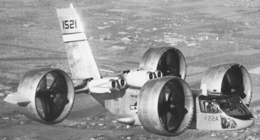
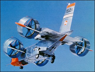
The X-22A was designed for evaluation of the tilting-duct concept in an airframe that might form the basis of a light V/STOL transport. It was also designed to provide a versatile platform capable of general research on V/STOL handling qualities using a variable stability control system.
The Tri-Service V/STOL Transport Program addressed needs of the Army, Navy, and Air Force, to develop a small number of prototype V/STOL transport aircraft that used different concepts and to perform operational evaluations of their usefulness.
The Navy studies showed that a duel tandem ducted fan configuration permitted a shorter wing span for a given weight, allowing a stubbier design that could fit on existing carrier elevators and would eliminate the need for complex wing folding mechanisms. The duct around each of the four props also would improve propeller efficiency and provide a safety benefit to personnel working on a ship’s flight deck.
The Navy awarded a $27.5 million contract for the design and development of two identical X-22s to Bell Helicopter of Niagara Falls, NY, in November 1962. Bell’s internal designation was the Model D2127. Bell had already Bell built and flew the Air Test Vehicle and X-14 VTOL research aircraft. Representative of a possible small V/STOL transport, the X-22 could carry a 540kg payload and could carry up to six passengers. Its length and wingspan were each a little over 11.9m, and maximum gross weight was 7530kg.

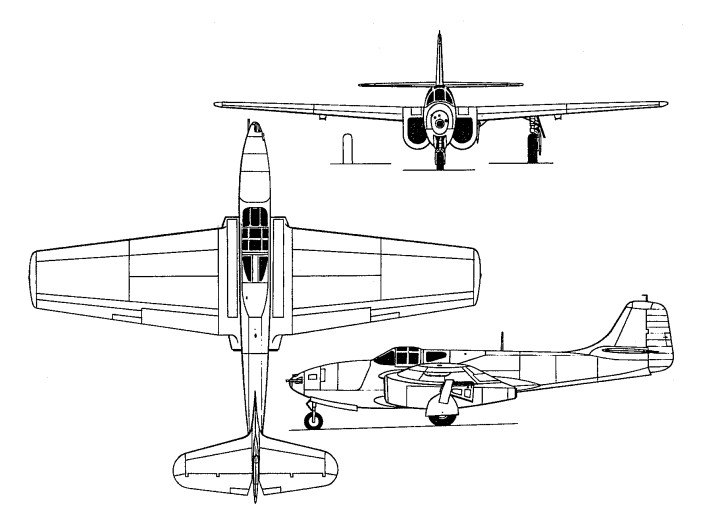
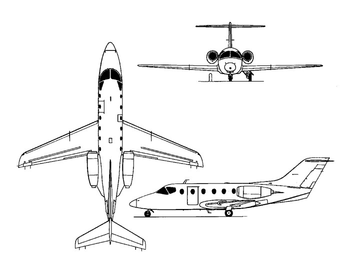
The rectangular fuselage accommodated at its rear a wide-chord wing fitted on its leading edges with two groups of two 1250-shp (932-kW) General Electric YT58-GE-8B/D turboshafts to drive four propellers (or fans) located inside annular ducts. These last were located at the tips of the wings and the short span foreplane and could be turned between the vertical (for vertical take-off and landing) and the horizontal (for forward flight). Change in the propeller pitch produced the thrust modulation for control, and was supplemented by movement of aileron in the slipstream of each duct. The “B” and “D” designations on the engines referred to two engine configurations that differed only by their fuel controllers. They powered a common drive shaft that turned all four props. These engines had both controllers and switched between them automatically based on whether the X-22 was operating in hover mode or cruise mode. 465 gallons of useable fuel was carried in fuselage tanks.
The power transmission system consisted of a total of ten gearboxes. It reduced the engine’s nominal 19,500 revolutions per minute speed down to the propellers’ nominal 2,600 revolutions per minute. This arrangement also allowed all four props to continue operating with any number of engines failed or intentionally shut down.
The four Hamilton Standard propellers, 2.1m diameter, 3-bladed props were fabricated of fiberglass bonded to a steel core, making them 25 percent lighter than metal props yet giving them three times the fatigue strength. A nickel sheath was mounted over the leading edge. Very high prop efficiency was achieved by placing the props inside of the ducts, so much so that the X-22 could still take off on three engines, fly on two, and make a conventional landing with only one. The two forward ducts were mounted to small pylons on the forward fuselage, and the two rear ducts were mounted to stubby, dihedralless wings on the aft fuselage. Hydraulic actuators rotated each of the four ducts, but mechanical and electrical interconnections insured that all rotated together.
Thrust control could be obtained by varying the blade angle. Four elevens, one placed at the rear of each ducted fan assembly, were the only control surfaces. Placing the elevons in the prop slipstream made them very effective, even at low airspeeds. Despite the significant looking vertical stabilizer, there was no rudder. Movement of the elevons and changes to the prop pitch achieved all flight control.
Flight control in horizontal flight was achieved using a conventional looking control stick for pitch and roll. Moving the stick caused the elevons to move, either differentially between the front and rear for pitch, or differentially on left and right sides for roll. Yaw was achieved by moving the rudder pedals, which changed the propeller blade angles to produce differential thrust. There were also throttles for each engine and a lever to control the angle of the ducts. In forward flight, the front ducts were rotated to 3 degrees up from horizontal and the rear ducts rotated to 2 degrees below horizontal. This gave an optimum incidence of 5 degrees between the two pairs.
The cockpit arrangement included two zero-zero ejection seats set side-by-side, full conventional instrument displays (plus a master tachometer for propeller revolutions and a duct angle indicator) duplicated for each pilot. Engine controls were gathered on the central console.
While hovering, the pilot used the same control stick to control pitch and bank motions. Stick inputs caused the flight control computer to command minute changes to the prop blade angles to vary the thrust, causing the X-22 to tip forward, aft, or sideways. Yaw was controlled by moving the rudder pedals, by differential movements of the elevons between the left and right sides. The pilot also could rotate the ducts to assist the fore/aft motion during hover.
During transition, with the ducts at some intermediate angle, the pilot’s control inputs produced mixed propeller pitch and elevon deflections. The ratio of mixing between the props and elevons was a function of the duct angle. The ducts rotated at 5 degrees per second.
The X-22’s flight controls also included a variable stability system. This was another flight control computer that modified the basic airplane responses so that the characteristics of other aircraft, either real or imagined, could be produced. The variable stability system followed algorithms that were developed specially for each test and programmed into the computer. They produced extra control surface motions that caused the X-22’s flight characteristics to be varied, thus producing motions that are not characteristic to the X-22 airframe, but rather to the aircraft being simulated. This gave the X-22 the capability to perform research that would be applicable to a broad range of other aircraft, not just the unique characteristics of the X-22 itself. The Cornell Aeronautical Laboratory designed the variable stability system.
The first X-22, US Navy Bureau Number 151520, rolled out on May 25, 1965, and was followed by fifty hours of propulsion tests in a test stand. The flight test program was undertaken by Calspan Corporation, in Buffalo, New York, under the auspices of the U.S. Navy. The first flight in hovering mode was not made until March 17, 1966. On this 10-minute flight, four vertical take-offs and landings and a 180 degree turn were made. It then performed a series of STOL take-off and landing tests with the ducts tilted at 30 degrees. The first X-22 was damaged beyond repair on its fifteenth flight on August 8, 1966. It had flown only 3.2 hours, but suffered a dual hydraulic failure about four miles from its base at Niagara Falls Airport. The first transition from wing-borne flight to vertical flight was made under the stress of an emergency landing. The fuselage broke in half, with the rear section coming to rest inverted. While the aircraft was lost, neither pilot was injured. Swivel fittings were used in the ducts to provide hydraulic fluid to the elevon actuators. Both failed due to excess vibration. The fix included replacing the swivel fittings with loops of flexible tubing, replacing the aluminum hydraulic lines with ones made of stainless steel, and placing additional clamps on the hydraulic lines to minimize vibration.
The first was damaged beyond economical repair and it was cannibalized to keep the second aircraft flying, although the fuselage was retained for use as a ground simulator at Calspan.
The second X-22, BuNo 151521, rolled out took place on 30 October, 1965 and flew on 26 January, 1967, with Stanley Kakol and Richard Carlin in the cockpit, for a first 10-minute hover flight. Bell test pilots Stanley Kakol and Paul Miller were at the controls. The first transition being successfully made on 3 March.
With pilots from Bell, the Army, Navy, and Air Force, the X-22 flew frequently over the next several years. At the completion of the Tri-Service testing in January of 1971, the X-22s completed 228 flights, 125 flight hours, performed over 400 vertical take-offs and landings, over 200 short take-offs and landings, and made over 250 transitions. It also hovered at 2440m of altitude and achieved forward speeds of 507km/h. These flights demonstrated that the X-22 had good basic stability and that vertical take-offs and landings could be performed easily. Operation in ground effect was a little less stable, but still positive. Hovering was easier than in most helicopters. In horizontal flight, all responses to pilot control inputs were excellent. Transitions were accomplished with minimum pilot workload. Landing position could be controlled precisely. The aircraft was still controllable without augmentation, but required a significant increase in pilot workload. This system provided rate damping in pitch, roll, and yaw only during hover and low speed flight.
With the Navy satisfied with the basic operation, they awarded a contract to Cornell in July 1970 to operate and perform flight research using the X-22, with particular emphasis on operating in the variable stability mode.

Over the next ten years, Calspan flew five test programs:

  • August 1971 – February 1972: evaluation of steep STOL approach paths of 6-10 degree glide slopes, at airspeeds of 120-150km/h, with a variety of oscillatory characteristics in the pitch mode.
    June 1972-February 1973: continuation of previous effort, but with variation of roll and yaw oscillatory characteristics.
  • October 1973 – April 1975: evaluation of control, display, and guidance requirements for STOL instrument approaches. Determined desirable control system requirements and information displays for pilot use to permit transition from forward flight to a decelerating steep approach and then to a hover at 30m, followed by a touchdown, all under instrument conditions.
  • February 1977 – March 1978: expanded the previous experiment by evaluating the usefulness of a head-up display for STOL instrument approaches. Used precision radar distance measuring equipment to establish the aircraft’s position within 7.62mm. Evaluated a variety of display formats that presented data to the pilot, such as attitude, airspeed, altitude, horizontal location, and range to touchdown. Also, simulated the AV-8B, a specific aircraft, rather than a generic set of aircraft characteristics.
  • November 1978 – May 1980: generated flying quality and flight control design requirement data for V/STOL aircraft performing shipboard landings. In performing this task, typical shipboard pitching and rocking motions had to be added to the guidance beam, then various compensation schemes were programmed into the flight computer on the X-22. Hover, and then simulated touchdowns at 30m were performed.

Numerous problems were discovered and fixed during testing. While all were fixed, they were not necessarily fixed in an optimum manner, as would be done for a production aircraft. Further development may have provided an optimal solution. But, being a research aircraft, a fix that worked for the intended mission was good enough. Some of them included the following:

  • Failure of the linkage synchronizing the front and rear duct angles, resulting in the front ducts rotating to 30 degrees while the rear ducts remained vertical. Fortunately, this happened on the ground. The aluminum shaft that transmitted the proper duct angle was replaced with one made of stainless steel.
  • In forward flight with the ducts near the stall angle of attack, the airflow from the lower lip separated from the duct surface as it entered the duct, causing a very loud buzzing as the turbulent flow hit the prop. Installing a number of vortex generators on the bottom inner-lip of each duct reduced this problem significantly.
  • A number of fatigue cracks developed on the inside of the duct skin and ribs. Apparently this was caused by a wake of very low pressure being pulled behind each prop blade. Thus, for each revolution of the prop, the surface was hit with three pulsations of high, then low pressure. This was corrected by replacing the ribs with slimmer ones, then building up an eighteen-inch wide ring of fiberglass inside each duct, maintaining the 0.95cm clearance between the prop tip and the wall.
    The program office within the Navy that oversaw the X-22’s testing was disbanded. Calspan sought added research programs, but the most they could accomplish was to get the Naval Test Pilot School to use the aircraft for some V/STOL demonstration flights for their students during 1981 and 1982. The aircraft made its last flight in October 1984. Ownership was transferred to the Naval Aviation Museum at Pensacola, Florida, but the museum never had any desire to display unique aircraft that were not typical of Naval aviation use. The X-22 remained in storage at Calspan’s facility at Buffalo Airport in hopes that further projects would return this unique test vehicle to service, or at least be acquired by an aviation museum.
    No further work ever arose, and many efforts to transfer the X-22 to an appropriate museum in the western New York area fell through. In 1995, Calspan moved it outdoors because they needed the hangar space. To protect it from the elements, the Buffalo & Erie County Historical Society paid to cover the X-22 in a plastic wrapping. In 1998, the newly formed Niagara Aerospace Museum at Niagara Falls, NY, acquired the X-22 and placed it on display.

For two full years, the X-22A was involved in a flight-test programme with Bell and the NASA. During this period some 220 flights and 110 flying hours were logged. This phase was followed, in January 1968, by a first military preliminary evaluation during which the X-22A was examined by pilots and engineers of the three Services and accomplished fourteen flights. A second military evaluation took place at the beginning of the following April. During this period, the X-22A demonstrated. good performance such as a sustained hover at an altitude of 2400m. On 19 May, 1968, the X-22A was officially taken on charge by the US Navy which turned it over almost immediately to Calspan Corp responsible for the test programme on behalf of the Navy. The prototype had been equipped with an automatic flight control system known as LORAS (Linear Omnidirectional Resolving Airspeed System). This programme, which was broken down into several tasks, totalled 273 flights, 279.9 flying hours, 130 VTOL take-offs and 236 VTOL landings. The aircraft was flown until the autumn of 1984 when flight testing was considered terminated. The X-22A made its last flight in 1988.

Engines: 4 x General Electric YT58-GE-8B/D turboshaft, 932kW / 1250hp
Wingspan: 11.96m / 39 ft 3 in
Length: 12.06m / 39 ft 7 in
Height: 6.3m
Take-off weight: 8172kg
Empty weight: 4302kg
Max speed: 370 km/h
Cruising speed: 343km/h
Range: 716km
Ceiling: 15,000 ft.
Fastest Flight: 255 mph
Total Flights: 500+
Highest Flight: 27,800 feet (approx)

Bell X-14

The Bell X-14 was produced as a vertical take-off prototype and achieved its first hovering flight on 17 February l957. The X-14 was originally created to explore the feasibility of operating a VTOL aircraft from a normal pilot station using standard flight instruments and references. Of equal importance, the X-14 was to demonstrate various VTOL systems and engine technologies—the aircraft was the first to demonstrate the concept of using vectored jet thrust as the only power system.
The airframe was as simple and light as possible, and was characterized by an open cockpit and fixed tailwheel landing gear. In its original form the aeroplane was powered by a pair of Bristol Siddeley Viper turbojets located side-by-side in the extreme nose of the aeroplane exhausting via nozzles on the sides of the aeroplane on the centre of gravity. For vertical take-off the nozzles were vectored directly downward, and for transition into forward flight were vectored gradually aft. The first successful transition was accomplished in May 1958, and the aeroplane was later re-engined with General Electric J85 turbojets. The X-14 made its last flight on 29 May 1981.
The X-14 successfully demonstrated that the concept of vectored jet thrust was viable, as subsequently used on the BAe/McDonnell Douglas Harrier. Flight tests using the X-14’s variable stability control system resulted in major contributions to the understanding of V/STOL handling characteristics. The X-14 also proved useful as a testbed for various unique V/STOL concepts, such as NASA’s direct side-force maneuvering system.
Over 25 pilots from around the world “previewed” V/STOL handling qualities in the X-14 prior to making test flights in other V/STOL designs. The single X-14 continued flying for nearly a quarter century before being retired to the Army Aviation Museum at Fort Rucker, Alabama. It is currently in storage at a private collection in Indiana.

Fastest Flight: 172 mph
Highest Flight: 18,000 feet (approx)

Bell X-5

The Bell X-5 was produced to investigate the aerodynamic consequences of altering the wing geometry in flight, and first flew on 20 June 1951. Work on the two X-5s began in 1948, the basis of the design being the Messerschmitt P.1101 prototype that had almost been completed by the Germans at the end of World War II. Two X-5s were manufactured by Bell, differing from their German ancestor primarily in being able to adjust their wing sweep angle in flight. The variable sweep wing could be adjusted to 20, 40 or 60 degrees the hydraulic operating mechanism automatically compensating for the inevitable shift in the position of the design’s centre of gravity.

Powered by a 4900-lb (2222-kg) thrust Allison J35-A-1; turbojet located in the lower fuselage and exhausting under the tail boom. Special fairings were also fitted to ensure that the leading and trailing edges of the wing roots presented smooth aerofoil surfaces at all times.

Bell X-5 Article

The first prototype (50-1838) was completed on February 15th, 1951 and first flown on June 20th, 1951. A second prototype (50-1839) followed into the air on December 10th, 1951. Both airframes accounted for some 200 total flights with the first prototype netting 133 flights alone. All three wing sweep positions were trialed on the first prototype’s ninth flight with success.

The Bell X-5 was produced to investigate the aerodynamic consequences of altering the wing geometry in flight, and first flew on 20 June 1951. Work on the two X-5s began in 1948, the basis of the design being the Messerschmitt P.1101 prototype that had almost been completed by the Germans at the end of World War II. Two X-5s were manufactured by Bell, differing from their German ancestor primarily in being able to adjust their wing sweep angle in flight. The variable sweep wing could be adjusted to 20, 40 or 60 degrees the hydraulic operating mechanism automatically compensating for the inevitable shift in the position of the design’s centre of gravity.

Powered by a 4900-lb (2222-kg) thrust Allison J35-A-1; turbojet located in the lower fuselage and exhausting under the tail boom. Special fairings were also fitted to ensure that the leading and trailing edges of the wing roots presented smooth aerofoil surfaces at all times.

The first prototype (50-1838) was completed on February 15th, 1951 and first flown on June 20th, 1951. A second prototype (50-1839) followed into the air on December 10th, 1951. Both airframes accounted for some 200 total flights with the first prototype netting 133 flights alone. All three wing sweep positions were trialed on the first prototype’s ninth flight with success.

In practice, it was found that the X-5 inherited some particularly vicious stall-spin instability characteristics. The cause was believed to be the positioning of the tail section within the design and compounded by the position of the vertical tail fin itself. As the wing sweep changed, essentially the entire aerodynamic qualities of the aircraft changed with it. The resulting action could lead the aircraft into an irrecoverable spin – this eventually occurring on October 14th, 1953 – the second prototype was lost to such a spin while running its wing sweep at 60-degrees, killing Air Force test pilot Captain Ray Popson.

The program was shelved and ultimately cancelled by the USAF. Testing did continue on with the first prototype into 1955 after which the aircraft served out the rest of her term as a chase plane until early 1958.

During Neil Armstrong’s first (and only) flight in the Bell X-5 in October 1955, the landing gear door fell off. Armstrong recalled;
“My checkout pilot was Jack McKay, and he explained that they often had trouble getting the nose gear tucked up. So, after take off, when retracting the gear, you were advised to nose over and go for about half a G. That would help get the nose gear in place, due to less download on the gear. So I attempted to do it, but it didn’t seem to be locking up. In thee meantime, I was nosing over, getting into a nose down position and, of course, the aircraft was speeding up, and I suspect that I actually ‘oversped’ the gear-limit speed, knocking the fairing door off. I never got the indication that the gear was completely retracted, so I put it back down and wasn’t able to conduct my flight plan. I never got a chance to fly the airplane again. They decided it was at the end of its research lifetime”.

The remaining Bell X-5 was handed over to the National Museum of the United States Air Force in Dayton, Ohio, in March of 1958 where it resides even today as part of the Research & Development Gallery at Wright-Patterson Air Force Base.

Engine: 1 x Allison J35-A-17 tubojet, 2223kg
Take-off weight: 4536 kg / 10000 lb
Wingspan: 5.66-9.39 m / 18 ft 7 in-30 ft 10 in
Length: 10.16 m / 33 ft 4 in
Height: 3.66 m / 12 ft 0 in
Max. speed: 1046 km/h / 650 mph

Bell 65 VTOL

The Bell 65 VTOL was built to test the practicability of rotatable turbojets providing thrust for both lift and forward propulsion. Two turbojets, which raised it off the ground for take-off, could be turned 90 degrees in the air to provide forward thrust, leaving the fixed wing to provide lift.

Bell 65 VTOL Article

Constructed largely from existing parts, power was provided by two 1000 lb thrust Fairchild J44 turbojets and one Continental-Turbomeca Palouste compressor.

Control at low-speed being obtained from compressed-air jets at the tail and wingtips fed by the Palouste.

Engines: two x 1000 lb thrust Fairchild J44 turbojet
Wingspan: 26 ft
Wing area: 130 sq.ft approx.
Length: 21 ft
Loaded weight: 2200 lb approx.

Bell XP-83

Bell’s last fighter, designed to replace the P-51, was the long range single seat XP-83.
On 24 March 1944 the USAAF tasked Bell to build a larger, longer-range jet fighter to superceed the P-51 Mustang. Bell assigned engineer Charles Rhodes to develop the XP-83, powered by two 1633kg thrust General Electric 1-40 (later J33-GE-5) turbojets, and to be armed with six 12.7mm Browning nose machine-guns.
First flown on 25 February 1945, the first XP-83 proved underpowered and unstable. The close proximity of the two low-slung powerplants caused hot exhaust gases to buckle the tail-plane unless, during run-ups, fire trucks were used to play streams of water over the rear fuselage.

The second XP-83 was completed with a slightly different bubble canopy and extended nose to accommodate six 15.2mm guns, the increase in barrel diameter being based on anticipated firepower needs for the planned amphibious invasion of Japan. This airframe was used in gunnery tests at Wright Field, Ohio.
Modified tailpipes, angled outwards, resolved the heat/buckling problem. Wind tunnel tests showed than a 45.7mm extension of the vertical tail would assure stability, though it is not clear whether this modification was actually made.
Except range, which was 3540km with underwing drop-tanks, the Bell XP-83 offered no improvement over the Lockheed F-80 Shooting Star then in production. For the post-war fighter-escort role, the newly independent USAF turned to the North American F-82 Twin Mustang. The redesignated XF-83 operated as a flying testbed for new technology.
The first XP-83 was assigned to a ramjet engine test programme. A hatch was cut in the belly to provide entry into the aft fuselage and an engineer’s station with a small port-side window, was created behind the pilot. Experimental ramjets were slung under the wings. The intent was for the XF-83 to serve as a proving vehicle for ramjet power, once aloft flying with the ramjets alone.
On 4 September 1947, just as this test programme had begun, a ramjet caught fire and flames spread to the wing. Pilot Chalmers ‘Slick’ Goodlin and engineer Charles Fay, without benefit of ejection seats, bailed out safely and the XF-83 was destroyed.

XF-83
Engines: 2 x General Electric J33-GE-5, 1814kg
Max take-off weight: 10927 kg / 24090 lb
Empty weight: 6398 kg / 14105 lb
Wingspan: 16.15 m / 52 ft 12 in
Length: 13.66 m / 44 ft 10 in
Height: 4.65 m / 15 ft 3 in
Wing area: 40.04 sq.m / 430.99 sq ft
Max. speed: 840 km/h / 522 mph
Ceiling: 13715 m / 45000 ft
Range w/max.fuel: 2784 km / 1730 miles
Crew: 1
Armament: 6 x 12.7mm machine-guns

Bell P-59 Airacomet

The XP59 Airacomet project was launched by USAF Major General Henry (Hap), Arnold on the 5th September 1941 began when he approached Bell Aircraft and asked them to build a new fighter based around the GE-1, a license made Whittle W2/B engine. The contract was signed on the 30th September with a deadline of eight months to produce the first of three prototypes designated XP-59A’s.

The Bell designers adopted a conventional approach which resulted in a preliminary design in just two months. This was approved and construction of the first prototype started which was shipped to Muroc Dry Lake (Now Edwards Air Force base) on the 12th September 1942 for ground tests. The engines called GE-1’s were built at the same time by General Electric and had an initial thrust of 1,250 lbs. This meant that two engines were required and in the Airacomet these were mounted side by side in the fuselage.

Bell P-59 Article

XP-59A Airacomet

After being trucked out to Muroc Dry Lake, California, draped in tarpaulin with a fake propeller attached, the
Airacomet was first flown on the 1st October 1942 by Robert M. Stanley, chief test pilot for Bell aircraft, although the official first flight was recorded as the 2nd of October.

The Airacomet was kept secret and it was only announced to the public in 1943.

XP-59

Named Airacomet, 13 development YP-59A aircraft followed during 1943-4 with the more powerful General Electric 1-16 (131) turbojet, and these were used primarily to provide basic flight data on turbojets. Production orders for 20 P-59A aircraft with J31-GE-3 engines and 80 P-59B aircralt with J31-GE-5 engines were awarded but, as a result of successful development of the Lockheed P-80 Shooting Star the last 50 of the latter were cancelled as superfluous, All production had been completed by the end of the war and many of the aircraft were issued to a special USAAF unit, the 412th Fighter Group, for use as drones or drone controllers, some aircraft having a second open cockpit in the nose for an observer. No P-59 ever achieved operational status, being found to lack adequate performance.

One XP-59A, a trade for a Gloster Meteor flown by the USAAF, was evaluated briefly by the RAF at Farnborough and wore British markings. Three more were flown by the US Navy under the designation XF2L-1.

Gallery

Bell XP-59 Airacomet
Span: 45ft 6in (13.87m)
Length: 38ft 2in (11.63 m)
Height: 12ft 4in (3.76 m)
Powerplant: Two General Electric I-A’s (each 1,250lb (567kg) thrust)
Maximum speed: 404 mph
Weight: Empty 7,320lb (3,320 kg), Loaded 12,562lb (5,698 kg)
Armament: 2x 37mm cannons
Range: 400 miles

Bell P-59A Airacomet
Engines: 2 x General Electric I-A turbojet engines generating 2,800lbs of thrust each.
Length: 38.16ft (11.63m)
Width: 45.51ft (13.87m)
Height: 12.34ft (3.76m)
Maximum Speed: 413mph (664kmh; 359kts)
Maximum Range: 240miles (386km)
Rate-of-Climb: 3,200ft/min (975m/min)
Service Ceiling: 46,194ft (14,080m)
Armament: 1 x 37mm cannon, 3 x 12.7mm machine guns
Bombload: 2,000lbs.
Accommodation: 1
Hardpoints: 2
Empty Weight: 7,937lbs (3,600kg)
Maximum Take-Off Weight: 12,699lbs (5,760kg)

P-59B Airacomet
Type: single-seat interceptor fighter
Powerplant: two 907-kg (2,000-1b) thrust General Electric J31-GE-5 turbojets
Span 13.87 m (45 ft 6 in)
Length 11.62 m (38 ft 1.5 in)
Height 3.66 m (12 ft 0 in)
Wing area 35.84 sq.m (385.8 sq ft)
Maximum speed 658 km/h (409 mph) at 10670 m (35,000 ft)
Cruise speed: 560 km/h / 348 mph
Climb to 3050 m (10,000 ft) in 3 minutes 20 seconds
Service ceiling 14040 m (46,200 ft)
Range 644 km (400 miles)
Empty weight 3704 kg (8,165 lb)
Maximum take-off 6214 kg (13.700 lb)
Crew: 1
Armament: one 20-mm M4 cannon and three 12.7-mrn (0.5-in) machine-guns in the nose

Beechcraft Premier 1 / Raython Premier 1

Raytheon developed the composite Premier I entry-level jet with a composite fuselage, empennage and control surfaces built of graphite and epoxy laminates with honeycomb construction, totaling more than a million miles of carbon-fiber filaments. The wings are aluminum.

Beechcraft Premier 1 Article

First flying in December 1998, the Premier offers typical jet speed and altitudes. The Premier I is also certified for single-pilot operation.

Gallery

Premier 1
Engines: two 2,300 lb Williams FJ44-2A
Seats: 2+6
Gross weight: 12,500 lb
Empty weight: 8,470 lb
Fuel capacity: 548 USgals
Max cruise: 451 kts
Range: 826-1,502 nm
Ceiling: 41,000 nm
Takeoff distance: 3,792 ft.
Landing distance: 3,170 ft.

Premier 1A
Engines: (2) Williams FJ44-2A
Max Cruise Speed: 451 kt @FL330
Max Range: 1460 nm
Max Certified Altitude: 41,000 ft
Takeoff Distance: 3792 ft
New Price 2009: US$6.4 million

Beechjet 400 / Hawker 400 / T-1A Jayhawk / Mitsubishi MU-300 Diamond / Raytheon Beechjet 400

Mitsubishi MU-300 Diamond

In 1977 Mitsubishi designed and built two prototypes of a twin-turbofan business aircraft designated the MU-300, the first flying on 29 August 1978; a one hour flight. A cantilever low-wing monoplane with a pressurised fuselage and retractable tricycle landing gear, the MU-300 was powered by two JT15D-4 turbofan engines, pod-mounted one on each side of the rear fuselage. Its twin turbofans are rated at 2,500 lbs. s.t. for takeoff and 2,375 lbs. s.t. for maximum continuous operation. Standard accommodation was provided for a crew of two and seven passengers. At the end of the development programme the prototypes were dismantled and shipped to the USA, where they were reassembled by the company’s US subsidiary Mitsubishi Aircraft International Inc. The two Diamond I prototypes underwent 350 hours of test flying in Japan before their arrival in the United States for FAA certification. Redesignated the Diamond I, the two aircraft were used in the US certification programme, which was granted on 6 November 1981. Initial customer deliveries began in July 1982 and 62 were built. The Diamond I wing design, with its advanced flight control system of full-span flaps, wing spoilers, and T-tail empennage, is built for optimum performance.

Beechjet 400 / Hawker 400 / Mitsubishi MU-300 Diamond Article

Mitsubishi developed an improved Model MU300-10 Diamond II, which was approved under FAA type certificate A14SW. Eleven examples were produced before the program was taken over by Beech and the aircraft re-certificated as the Beech Model 400 under new FAA type certificate A16SW. All the MU300-10 were subsequently converted to the Model 400 under Beech Service Bulletin Number 2140.

An improved version, the Diamond IA, fitted with uprated JT15D-4D engines giving overall performance increases, an EFIS cockpit and with maximum take-off weight increased to 7361kg, was announced in 1983 and the first of 27 built, distinguished by the extra port side window, was delivered in 1984. With an MTOW reduced to 7157kg, but with extra fuel, and more powerful JT15D-5 engines, a further eight aircraft were produced as the Diamond II.
Model 400 comprised serial numbers RJ-12 through RJ-65.

However, in December 1985, Mitsubishi sold the Diamond II design rights to Beech, together with components for 64 aircraft. These were assembled at Wichita and marketed as the Beechjet 400. Beech then initiated full manufacture of the type in 1989. The first Beech-assembled aircraft was rolled out on 19 May 1986 and deliveries began in June. By the beginning of 1989 46 Beechjets had been delivered. Beech is also providing support for previous Mitsubishi products, including the MU-2 and earlier Diamond versions.

The Beechjet 400A first flew on 22 September 1989.
The commercial Model 400A Beechjet was certificated on 20 June 1990, featuring increases in payload and ceiling, greater cabin volume, a rear lavatory and improved soundproofing. A Collins Pro Line 4 EFIS is fitted as standard. Deliveries of this version began in early 1990. By the beginning of 1991 beech had received orders for 113 slightly modified Model 400As In February 1990 the US Air Force chose the type as the airframe element of the Tanker/Transport Training System under the designation Beech 400T T-1A Jayhawk. Powerplants are 2,900 lb st (12.9 kN) P&W Canada JT15D-5 turbofans. The USAF requirement was for 211 aircraft and the first of these was delivered in July 1991 and entered service in March 1992, training KC-135, C-5, KC-10 and C-17 crews.
In 2003 its name changed once again to the Hawker 400XP (for ‘extended performance’) for a better fit into the Raytheon family of bizjets.

The Model 400A, serial number RK-1 and on, was a further development. The primary change was the introduction of the Rockwell Collins Proline IV EFIS system, plus other improvements including greater cabin volume, increased max takeoff weight and higher operating ceiling. (From 2003 and serial number RK-354 the aircraft was marketed as the Hawker 400XP.) Production ceased in 2010 with serial number RK-604.

Variation:
Nextant 400

Specifications:

MU-300 Diamond I
First built: 1981.
Engines: 2 x P&W JT15D-4, 2,500 lbs thrust.
Seats: 11.
Length: 48.3 ft.
Height: 13.8 ft.
Wingspan: 43.4 ft.
Wing area: 241 sq.ft.
Wing aspect ratio: 7.5.
Maximum ramp weight: 14,200 lbs.
Maximum takeoff weight: 14,100 lbs.
Standard empty weight: 8600 lbs.
Maximum useful load: 5200 lbs.
Zero-fuel weight: 10,800 lbs.
Maximum landing weight: 13,200 lbs.
Wing loading: 58.4 lbs/sq.ft.
Power loading: 2.8 lbs/lb.
Maximum usable fuel: 4200 lbs.
Best rate of climb: 3000 fpm.
Certificated ceiling: 41,000 ft.
Max pressurisation differential: 9 psi.
8000 ft cabin alt @: 41,000 ft.
Maximum single-engine rate of climb: 810 fpm.
Single-engine ceiling: 26,500 ft.
Maximum speed: 434 kts.
Normal cruise @ 37,000ft: 424 kts.
Fuel flow @ normal cruise: 1098 pph.
Stalling speed clean: 104 kts.
Stalling speed gear/flaps down: 91 kts.
Turbulent-air penetration speed: 208 kts.

Beechjet 400A
Engines: 2 x Pratt & Whitney Canada JT15D-5 turbofans, 1315kg / 2,900 lb st (s/n RK-1 through RK-507) / Pratt & Whitney Canada JT15D-5R (s/n RK-508 and after)
MCTOW: 16,100 lb / 16,300 lb. (serial number RK-347 and after, and aircraft with Kit
128-5202-0001 Increased Gross Takeoff Weight.)
Weight empty: 10116.5 lbs / 4588.0 kg
Wingspan: 13.25 m / 43 ft 6 in
Length: 14.75 m / 48 ft 5 in
Height: 4.19 m / 13 ft 9 in
Wing area: 22.43 sq.m / 241.43 sq ft
Wing load: 65.60 lbs/sq.ft / 320.0 kg/sq.m
Max. speed: 854 km/h / 531 mph
Cruise speed: 828 km/h / 515 mph
Landing speed: 87 kts / 161 km/h
Ceiling: 13715 m / 45000 ft
Service ceiling: 41011 ft / 12500 m
Initial climb rate: 4330.71 ft/min / 22.0 m/s
Range: 5375 km / 3340 miles
Noise Standard: FAR Part 36 Amendment 36-17
Max. No. of Seats: 11

Hawker 400XP
Engines two 2,965-lb. Pratt & Whitney JT15D-5 turbofans.
Seats 7-9.
Gross wt. 16,500 lb.
Empty wt. 10,550 lb
Fuel capacity 733 US gal.
Max cruise 450 kts.
Long range cruise 414 kts.
Range 874-1,687 nm.
Ceiling 45,000 ft
Takeoff distance 3,906 ft
Landing distance 3,514 ft

Beechcraft Fan Jet 400 / PD.290

The success of the Beech King Air 200 design prompted Beech to explore a jet-powered version. This was the PD.290 Fan Jet 400. The first prototype King Air 200 was re-engined with Pratt & Whitney Canada JT15D-4 turbofans in similar nacelles to the PT6A turboprops.

The aircraft was flown in this configuration for the first time on March 12, 1975. The jet-powered aircraft did not warrant production, and Beech later purchased the Mitsubishi Diamond design.

The last flight was made on September 30, 1977.