Boeing-Vertol 107 / CH-46 / Vertol YHC-1

In 1956, Vertol began preliminary design and engineering of a twin-turbine transport helicopter for commercial and military applications. The main objective was to take full advantage of the high power, small size and light weight of the shaft-turbine engines then becoming available. To achieve the best possible hovering performance, the traditional Vertol tandem-rotor layout was retained, and the turbines were mounted above the rear of the cabin, on each side of the aft rotor pylon. This results in maximum unobstructed cabin area and permits the use of a large rear ramp for straight-in loading of vehicles and bulky freight.

Boeing-Vertol 107 / CH-46 Article

Construction of a prototype, designated Model 107, was started in May 1957, and this aircraft flew for the first time on 22 April 1958, powered by two 641kW Lycoming T53 turboshaft engines. It was designed for water landing capability, without the addition of special flotation gear or boat hull design, and was intended to carry 23 to 25 passengers in normal airline standard accommodation.

Vertol 107 No.1

The new Model 107 prototype N74060 with two 877shp Lycoming T53 turbines flew on 12 August 1958.

In July 1958, the US Army ordered 10 Model 107s, designated YHC-1A; seven with the uprated 1065shp General Electric YT58 turbine and three with the Lycoming T53, and a rotor diameter increased by 0.6m.

YHC-1A

The first YHC-1A flew on 27 August 1959, but in the meantime, the US Army had ordered five YHC-1Bs (Model 114 later known as the CH-47 Chinook), a scaled-up variant which was better suited to meet its need for a tactical transport helicopter, and consequently the order for the Model 107 was reduced to only three machines (serials 58-5514 through -5516). These machines were used primarily to familiarize Army flight crews with the capabilities of turbine-powered helicopters, and all three were eventually returned to the manufacturer.

The third of these was later returned to the company which equipped it with 783kW General Electric T58-GE-6 turboshaft engines and rotors of increased diameter, and this derivative was fitted out with a commercial interior as the Model 107-II prototype. This first flew on 25 October 1960. By that time Vertol had become a division of The Boeing Company. The first production model of the airliner spec 107 II followed on 19 May 1961 and FAA certification was received on 26 January 1962, entering scheduled service with New York Airways 1 July that year. Eight helicopters were delivered and began scheduled services between mid town Manhatten and Kennedy and La Guardia aoirports. Following this initial order remaining commercial variants were built by Kawasaki.

When the US Navy set up a new design competition for a medium-lift transport helicopter in 1960, this was won by the Boeing-Vertol 107M, a modified version of the YHC-1A powered by T58-GE-8 engines in February 1961. A batch of 50 was initially ordered, the first of which was tested in October 1962. Ordered into production under the designation HRB-1 (changed to CH-46A Sea Knight in 1962), the 107M was used for troop transport. The first order for the CH-46A assault transport version for the US Marine Corps was placed in February 1991, with first flight on 16 October 1962. This basic model accommodates a typical total of 26 troops or 15 casualty litters.

In 1963 Sweden bought four more Boeing Vertol 107, bringing to 13 the total ordered for its Air Force and Navy, designated HKP-4.

Testing continued into late 1964, with the first US Marine squadrons taking these aircraft into service in early 1965.
Four squadrons were operating CH-46As by June 1965 and the type entered service in Vietnam in March 1966, replacing the Sikorsky H-34.During the V ietnam War the Marines also installed a 7.62mm machine gun, which was fired through the cabin door. A total of 498 have been ordered by the Marine Corps and 24 by the US Navy.
Several variants have been produced including the CH-46A for the Marines (160); the UH-46A Sea Knight for the US Navy (24) with first deliveries to Utility Helicopter Squadron 1 in July 1964) the CH-46D for the USMC, generally similar to the CH-46A, but with 1044kW T58-GE-10 turboshaft engines (266); the UH-46D for the US Navy (10); the UH-46B for evaluation by the USAF; the RH-46E minehunters for the US Navy, and the CH-46F for the Marines , generally similar to the CH-46D, but with additional avionics (174).
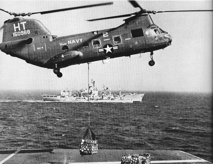
The US Navy UH 46 model accommodated a typical total of 26 troops or 15 casualty litters but also able to carry 3175 kg (7,000 lb) of cargo, including vehicles loaded through the full section rear ramp door, for use in the vertrep (vertical replenishment) of ships at sea. Both Sea Knight families can have rescue hoists and are equipped for limited amphibious operation, though they are not intended for sustained alighting on rough seas.
Some 669 Sea Knights were built; US Navy and Marine Corps models serving in Operation Desert Storm.
A total of 624 models were delivered by 1971, and most surviving examples have been subjected to major update programmes which include fitting glassfibre rotor blades. The best 273 Sea Knights in US Marine Corps service were progressively being rebuilt as CH 46E helicopters with the more powerful 1394kW General Electric T58-GE-16 turboshaft engines, replacing the 1,250 or 1,400 shp (932 or 1044 kW) T58 engines origi¬nally fitted, as well as numerous improvements to improve reliability, res¬cue capability and ability to survive a crash on land or on water. Since 1981, 368 kits were supplied to provide further modifications to im¬prove safety and reduce costs.
The CH/UH-46 carries a crew of three, 25 troops and troop commander. Door at front of troop compartment on starboard side. Door is split type; upper half rolls on tracks to stowed position in fuselage crown, lower half is hinged at the bottom and opens outward, with built-in steps. Loading ramp and hatch at rear of fuselage can be opened in flight or on the water. Floor has centre panel stressed for 1,464kg/sq.m. A row of rollers on each side for handling standard military pallets or wire baskets. Outer portion of floor is vehicle treadway stressed for 454kg rubber-tyred wheel loads. Cargo and personnel hoist system includes a variable-speed winch capable of 907kg cable pull at 9m/min for cargo loading or 272kg cable pull at 30m/min for personnel hoisting; it can be operated by one man. A 4,535kg capacity hook for external loads is installed in a cargo hatch in the floor.
The cabin is heated by a Janitrol combustion heater and hydraulic system provides 105kg/sq.cm pressure for flying control boost, 210kg/sq.cm for other services. Electrical system includes two 40kVA AC generators and a Leland 200A DC generator. Solar APU provides power for starting and systems check-out.
CH-46 has dual stability augmentation systems and automatic trim system.
Featuring two three-blade rotors in tandem, rotating in opposite directions. The CH/UH-46 has power-operated blade folding. Power is transmitted from each engine through individually overrunning clutches into the aft transmission, which combines the engine outputs, thereby providing a single power output to the interconnecting shaft which enables both rotors to be driven by either engine.
The structure is square-section stressed-skin semi-monocoque structure built primarily of high-strength bare and alclad aluminium alloy. Transverse bulkheads and built-up frames support transmission, power plant and landing gear. Loading ramp forms undersurface of upswept rear fuselage on utility and military models. Baggage container replaces ramp on airliner version. Fuselage is sealed to permit operation from water.
Non-retractable tricycle landing gear has twin-wheels on all three units. Oleo-pneumatic shock-absorbers manufactured by Loud (main gear) and Jarry (nose gear). Goodyear tubeless tyres size 8 x 5.5, pressure 10.55kg/sq.cm, on all wheels. Goodyear disc brakes.

Six utility models, almost identical to the CH-46A, were delivered to the RCAF in 1963-4 under the designation CH-113 Labrador, and 12 similar aircraft were built for the Canadian Army during 1964-5, these being designated CH-113A Voyageur. The CH 113 Labrador had a range of over 650 miles (1,050 km). Under a Canadian Armed Forces’ Search And Rescue Capability Upgrade Project (SARCUP), Boeing of Canada was contracted to modify six CH-113s and five CH-113As to an improved SAR standard by mid-1984, with extra fuel, weather radar, a water dam for use of the rear ramp at sea and an APU (auxiliary power unit).

CH-113 Labrador of 103rd Rescue Sqn, Gander

In 1962-3 Boeing Vertol supplied 14 Model 107-IIs to Sweden for service with the air force in the search and rescue role, and with the navy for ASW and minesweeping duties: both of these versions have the designation HKP-4. Sweden uses the Gnome engined HKP 7 version for ASW and mines¬weeping duties.

Kawasaki Heavy Industries obtained a licence in December 1965 to build the Model 107 in Japan in civil and military versions resulting in 12 new versions: the KV-107/11-2 commercial version for passenger transport adopted by Kawasaki, the Thai government and New York Airways; the KV-107/11-3 minehunters; the KV-107/11-4 for tactical transport, 59 of which have been built for the Japanese Ground Self-Defense Force; the KV-107/11-5 rescue version for the Japanese Air Self-Defense Force and the Swedish Navy (38 built); the KV-107/11-7 six-eleven-seat VIP transport version, only one of which has been built for the Thai government; and the KV-107/IIA version for hot climates and high altitudes.
Kawasaki obtained in 1965 exclusive rights to manufacture this tandem rotor helicopter and sell it worldwide. The first KV107II obtained Japanese and US type approval in Spring 1968. The 107 Model II standard accommodation is for two pilots, stewardess and 25 passengers in airliner. Seats in eight rows, in pairs on port side and single seats on starboard side (two pairs at rear of cabin) with central aisle. Airliner fitted with parcel rack and a roll-out baggage container, with capacity of approximately 680kg, located in underside of rear fuselage. Ramp of utility model is power-operated on the ground or in flight and can be removed or left open to permit carriage of extra long cargo.
The naval KV 107II 3 is a specialized MCM (mine countermeasures) helicopter, of which nine serve with the JMSDF’s 111th Air Wing. This version has up¬rated engines (1,400 shp/1044 kW) in¬stead of 1, 50 shp/932 kW) and com¬prehensive equipment for mine¬sweeping and retrieval, as well as long range tanks, cargo hook and towing gear.

Variants:

107 Model II: Standard commercial version, with two 932kW (1,250 shp) General Electric CT58 turboshaft. Available as an airliner with roll-out rear baggage container or utility model with rear-loading ramp.

CH-46A (formerly HRB-1) Sea Knight: US Marine Corps assault transport version of the 107 Model II powered by two 932kW General Electric T58-GE-8B turboshafts.

CH-46D Sea Knight: Generally similar to CH-46A, but with 1,044kW General Electric T58-GE-10 turboshaft and cambered rotor blades.

CH-46E Sea Knight: Upgraded CH-46A with 1,394kW General Electric T58-GE-16 turboshafts and other modifications including provision of crash attenuating seats for pilot and co-pilot, a crash and combat resistant fuel system and improved rescue system. Initial fleet modifications began in 1977, and the first CH-46E modified at Cherry Point NV, Naval Rework Facility was rolled out 3 August 1977.

CH-46F Sea Knight: Generally similar to CH-46D, with the same engines and rotor blades. Contains additional electronics equipment. All CH-46s delivered since July 1968 were of this version.

UH-46A Sea Knight: Similar to CH-46A. Ordered by US Navy for operation from AFS or AOE combat supply ships to transport supplies, ammunition and missiles as well as aviation spares to combatant vessels under way at sea. Secondary tasks include transfer of personnel and SAR. First deliveries in July 1964.

UH-46D Sea Knight: Generally similar to UH-46A, but with 1,044kW General Electric T58-GE-10 shaft turbine engines and cambered rotor blades. UH-46s delivered since September 1966 were of this version.

CH-113 Labrador: Six utility models delivered to RCAF in 1963-64 for SAR duties. Generally similar to CH-46A. Two 932kW General Electric T58-GE-8B turboshafts. Larger capacity fuel tanks (total 3,408 litres) giving a range of over 1,050km. All six upgraded under Search and Rescue Capability Upgrading Programme (SARCUP).

CH-113A Voyageur: Twelve aircraft in a similar configuration to that of CH-46A, delivered to Canadian Army in 1964-65 as troop and cargo carriers in logistical and tactical missions. Eight upgraded to SARCUP configuration.

Hkp 4C: Built for Royal Swedish Navy (45) and Air Force (10) in 1962-63, with Bristol Siddeley Gnome H.1200 turboshaft engines and fuel tanks of 3,786 litres capacity. Naval version has equipment for anti-submarine and mine countermeasures operations. Since upgraded with Gnome H.1400 turboshafts and new avionics.

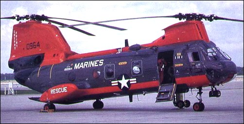
HH-46D: Rescue version in service with the US Navy.

UH-46D: Base utility and rescue helicopter. In service with the US Navy.

KV-107/II-2: airline version, with accommodation for two flight crew, a stewardess and 25 passengers; 11 built; improved KV-107/IIA-2 available

KV-107/11-3: mine counter-measures (MCM) version for JMSDF (two), plus seven of the uprated KV-107/11A-3 model

KV-107/II-4: tactical cargo/troop transport for JGSDF with strengthened cabin flooring; 42 supplied as such, with the last of 18 uprated KV-107/ IIA-4 versions delivered in late 1981

KV-107/II-5: designation of 13 long-range SAR helicopters for JASDF; 19 uprated, but otherwise similar aircraft, are designated KV-107/IIA-5, the last three being delivered during 1981; eight KV-107/II-5s supplied to Swedish navy without powerplant, these having Rolls-Royce Gnome H.1200 turboshafts installed in Sweden; Swedish navy designation HKP-4C

KV-107/II-7: designation of one six/eleven-seat VIP transport

KV-107/11A-17: designation of single long-range transport for Tokyo Metropolitan Police Department; has a forward passenger compartment and aft cargo hold

KV-107/II-SM-1: designation of four helicopters equipped as firefighters

KV-107/IIA-SM-2: aeromedical and rescue version

Gallery

Specifications:

YHC-1 Chinook
Engines: 2 x GE T58 gas turbines
Main rotor: 48’4″
Length: 52’8″
Speed: 155 mph

Model 107
Engines: 2 x Lycoming T53 turboshaft
Rotor diameter: 50 ft / 15.24 m
Fuselage length: 44 ft 7 in / 13.59 m
Overall length: 25.4o m / 83 ft 4 in
Height: 5.09 m / 16 ft 9 in
Cruise: 120 kt / 222 kph
Endurance: 2.2 hr
Passenger capacity: 25

Model 107
Engines: 2 x Lycoming T53 turboshaft, 641kW, 877shp
Rotor diameter : 60.007 ft / 18.29 m
Length : 99.016 ft / 30.18 m
Max take off weight : 50406.3 lb / 22860.0 kg
Max. speed : 161 kt / 298 km/h
Range : 100 nm / 185 km
Crew : 2+44

Model 107-II prototype
Engines: 2 x General Electric T58-GE-6 turboshaft, 783kW

107 Model II
Engines: 2 x General Electric CT58 turboshaft, 932kW (1,250 shp)

YHC-1A
Engines: 2 x General Electric YT58 turbine, 1065shp

107M / CH-46A / HRB-1 Sea Knight
Engines: 2 x General Electric T58-GE-8B turboshafts, 932kW
accommo¬dates 26 troops or 15 casualty litters.

CH-46D Sea Knight:
Engines: 2 x General Electric T58-GE-10 turboshaft, 1,044kW
External hook capacity: 4,535kg

CH-46E Sea Knight:
Engines: two 1,870 shp (1394 kW) General Electric T58 16 turboshafts.
Main rotor diameter: 15.24 m (50 ft 0 in)
Length overall: 25.70 m (84 ft 4 in)
Height: 5.09 m (16 ft 8.5 in)
Rotor disc. Area: 364.8 sq.m (3,927.0 sq ft)
Fuselage length: 44.82ft (13.66m)
Empty weights: 5240kg (11,5851b)
Maximum take off: 9706 kg (21,400 lb)
External hook capacity: 4,535kg
Maximum speed: 267 km/h (166 mph / 144kts)
Cruising speed: 193 km/h (120 mph)
Range (3000 kg/6,614 1b payload): 175 km (109 miles)
Maximum Range: 690miles (1,110km)
Rate-of-Climb: 1,715ft/min (523m/min)
Service Ceiling: 9,498ft (2,895m; 1.8miles)
Accommodation: 3 + 25

CH-46F Sea Knight
External hook capacity: 4,535kg

RH-46E

UH-46A Sea Knight
External hook capacity: 4,535kg

UH-46B
External hook capacity: 4,535kg

UH-46D Sea Knight:
Engines: 2 x General Electric T58-GE-10 turboshafts, 1,044kW
External hook capacity: 4,535kg

CH-113 Labrador
Engines: 2 x General Electric T58-GE-8B turboshafts, 932kW, 1250 shp
Rotor dia: 50 ft 0 in (15.24 m)
Length: 83 ft 4 in (25.4 m)
Height: 16 ft 8.5 in (5.09 m)
Max TO wt: 21,400 lb (9707 kg)
Max level speed: 157 mph (253 kph)
Fuel capacity: 3,408 lt
Range: 1,050+km

CH-113A Voyageur

Hkp 4C
Engines: 2 x Bristol Siddeley Gnome H.1200 turboshaft (upgraded with Gnome H.1400)
Fuel capacity: 3,786 lt

HH-46D

UH-46D

KV-107/II-2
Engines: 2 x 1,250 shp/932 kW
Crew: 2
Accommodation: 1 stewardess, 25 passengers

KV-107/IIA
Engines: 2 x Ishikawajima Harima CT58 IHI 140 1 turbo¬shaft, 1250 shp/932 kW

KV-107/IIA-2
Engine: 2 x General Electric CT58-140-1 turboshaft, 1044kW / 1,400 shp
Rotor diameter: 15.24m
Length with rotors turning: 25.4m
Height: 5.09m
Max take-off weight: 9707kg
Max speed: 254km/h
Cruising speed: 241km/h
Service ceiling: 5180m
Range with max fuel: 1097km
Accommodation: 1 stewardess, 25 passengers

KV-107/11-3
Engines: 2 x 1,400 shp/1044 kW

KV-107/IIA-3
Engine: 2 x 1,400 shp General Electric CT58 40 I, or 1,250 shp Ishikawajima Harima CT58 IHI 140 1 turbo¬shaft

KV-107/II-4
Engines: 2 x 1,250 shp/932 kW

KV-107/II-5
Engines: 2 x 1,250 shp/932 kW

KV-107/II-7
Engines: 2 x 1,250 shp/932 kW
Seats: six/eleven-seat VIP transport

KV-107/11A-17
Engine: 2 x 1,400 shp General Electric CT58 40 I, or 1,250 shp Ishikawajima Harima CT58 IHI 140 1 turbo¬shaft

KV-107/II-SM-1

KV-107/IIA-SM-2
Engine: 2 x 1,400 shp General Electric CT58 40 I, or 1,250 shp Ishikawajima Harima CT58 IHI 140 1 turbo¬shaft

H-46 / Lower side-view KV-107

Boeing T-X / T-7 Red Hawk

The USAF’s Air Education and Training Command (AETC) began developing the requirements for a replacement for the Northrop T-38 Talon as early as 2003. Originally, the replacement trainer was expected to enter service around 2020. A fatigue failure of a T-38C killed the two-person crew in 2008 and the USAF advanced the target date of initial operational capability (IOC) to 2017. In the Fiscal 2013 budget proposal, the USAF suggested delaying the initial operating capability to FY2020 with the contract award not expected before FY2016. Shrinking budgets and higher priority modernization projects pushed the IOC of the T-X program winner to “fiscal year 2023 or 2024”. Although the program was left out of the FY 2014 budget entirely, the service still viewed the trainer as a priority.

In cooperation with its Swedish aerospace partner, Saab, Boeing’s submission to the competition was the Boeing T-X, a single-engine advanced jet trainer with a twin tail, tandem seating, and retractable tricycle landing gear. The submitted aircraft and demonstration models featured a General Electric F404 afterburning turbofan engine.

The Boeing T-X jet fighter trainer was developed in partnership with Swedish defense contractor Saab. The partners’ strategy was demonstrating to the Air Force and the US Department of Defense the ability of the “blank sheet” aircraft to compete with off-the-shelf competitors for a contract in terms of quick delivery.

It has twin tails derived from Boeing’s F/A-18 for greater maneuverability and a high angle of attack, stadium seating, an advanced cockpit with embedded training, and the ability to blend with state-of-the-art ground-based training. In addition, it’s billed as being maintenance-friendly in anticipation of decades of service.

Boeing revealed its aircraft to the public on 13 September 2016. The first T-X aircraft flew on 20 December 2016, as BTX-1, on a 55-minute flight. Two protypes were built.

On 27 September 2018, Boeing’s design was officially announced as the USAF’s new advanced jet trainer to replace the T-38 Talon. A total of 351 aircraft and 46 simulators, maintenance training and support are to be supplied at a program cost of US$9.2 billion.

In May 2019, Saab announced that it would open a U.S. manufacturing facility for the T-X in Indiana in partnership with Purdue University.

On 16 September 2019, the USAF officially named the aircraft the “T-7A Red Hawk” as a tribute to the Tuskegee Airmen, who painted their airplanes’ tails red, and to the Curtiss P-40 Warhawk, one of the aircraft flown by the Tuskegee Airmen.

U.S. Air Force publicity photo of the T-7A Red Hawk showing Red Tail livery

Boeing intends to offer an armed version of the T-7 as replacement for aging Northrop F-5 and Dassault/Dornier Alpha Jet fleets around the world.

A second T-X was being ground tested in 2017.

The design officially entered production in February 2021 as T-7A for the U.S. Air Force.

Powerplant: 1 × General Electric F404-GE-103, 11,000 lbf (49 kN) thrust dry, 17,000 lbf (76 kN) with afterburner
Crew: 2

Boeing Bird of Prey

The Boeing Bird of Prey was a black project tested at the top secret Groom Lake facility. The Bird of Prey, named after the Klingon one in Star Trek, was a stealth technology demonstrator. Developed by the McDonnell Douglas Phantom Works (which later became part of Boeing), only one Bird of Prey technology demonstrator was built, taking to the air in the fall of 1996.

Funded entirely by the company, Bird of Prey was a relatively low cost programme at $67 million, utilising off-the-shelf components. To keep expenses down, the Aircraft used a Pratt & Whitney JT15D which is commonly found in Citation Jets and the Beechjet. It is speculated that the aircraft tested active camouflage, the ability to match the local environment, changing colour and luminosity. Cloaking! Another reason to reference Star Trek. Despite its radical appearance, the aircraft was aerodynamically stable enough to use manual hydraulic controls rather than fly-by-wire, reducing both development time and cost.

The aircraft made 39 flights before the programme’s conclusion in 1999, helping develop technologies since used on Boeing’s X-45 and X-47 unmanned combat air vehicles.

After the programme’s conclusion, Bird of Prey was stored in Dyson’s Dock for three years before being declassified in October 2002. In October 2002 Boeing revealed the existence of the Bird of Prey.

The sole Bird of Prey can be found at the Museum of the United States Air Force in Dayton Ohio.

Gallery

Boeing 520 / T60

The Model 520 (military designation Boeing T60) was a family of small turboshaft / turboprop engines produced by Boeing, based on Boeing’s earlier Model 500 gas generator and Model 502 turboshaft engines.

Variants:

YT60-BO-2A
Military turboshaft verion for testing.

520-2
(YT60-BO-2A) Free power turbine turboshaft rated at 475 hp (354.21 kW)

520-4
Turboprop rated at 475 hp (354.21 kW)

520-6
Direct drive turboshaft rated at 550 hp (410.13 kW) military power

520-8
Turboprop rated at 550 hp (410.13 kW)

Specifications:

520-6
Type: Turboshaft
Length: 54.1 in (1,374 mm)
Diameter: 25.14 in (639 mm) maximum height
Dry weight: 250 lb (113 kg)
Compressor: Single-stage centrifugal flow
Combustors: 2 reverse flow can combustors
Turbine: 1x radial gas generator power turbine stage
Fuel type: Aviation kerosene
Oil system: pressure spray/splash, oil specification: MIL-L-7808
Maximum power output: 550 hp (410.13 kW) military rating at 6,000 output shaft rpm
Overall pressure ratio: 6:1
Turbine inlet temperature: Jet pipe Temperature: 1,025 °F (552 °C)
Specific fuel consumption: 0.67 lb/hp-hr (0.41 kg/kW-hr)
Power-to-weight ratio: 2.2 hp/lb (3.616 kW/kg)

Boeing 502 / T50

QH-50D with T50 engine

The Boeing T50 (company designation Model 502) was a small turboshaft engine produced by Boeing. Based on Boeing’s earlier Model 500 gas generator, the T50’s main application was in the QH-50 DASH helicopter drone of the 1950s. An up-rated version designated Model 550 was developed to power the QH-50D and was given the military designation T50-BO-12.

Variants:
T50-BO-4
270 hp (201.34 kW) at 6,000 output rpm, military rating turboprop.
T50-BO-6
T50-BO-8
300 hp (223.71 kW) at 5,950 output rpm, revised reduction gear ratio, fuel system and other changes.
T50-BO-8A
T50-BO-10
330 hp (246.08 kW) at 6,000 output rpm
T50-BO-12
502-10C
502-10V
(T50-BO-4)
502-10VB
325 hp (242.35 kW) at 3,000 output rpm, variant of -10V / T50-B0-4 with revised reduction gear ratio.
502-10VC
(T50-BO-8)
502-11
502-12B
502-W
502-14
(T50-BO-10)
550-1
(T50-BO-12)
Applications
T50 (Model 502)
Gyrodyne QH-50 DASH
Kaman K-225
Kaman HTK-1
Kaman K-1125
XL-19B Bird Dog
Radioplane RP-77D

GT502
Stridsvagn 103

Specifications:

T50-BO-10 / 502-14
Type: Turboshaft
Length: 37.2 in (945 mm)
Diameter: 22.5 in (572 mm)
Dry weight: 215 lb (98 kg)
Compressor: Single-stage centrifugal flow
Combustors: 2 can combustors
Turbine: 1x axial gas generator power turbine stage + 1x axial free-power turbine stage
Fuel type: Aviation kerosene
Oil system: pressure spray/splash, oil specification: MIL-L-7808
Maximum power output: 330 hp (246.08 kW) military rating at 6,000 output shaft rpm
Overall pressure ratio: 4.35:1
Turbine inlet temperature: Jet pipe Temperature: 1,140 °F (616 °C)
Specific fuel consumption: 0.87 lb/hp-hr (0.532 kg/kW-hr)
Power-to-weight ratio: 1.535 hp/lb (2.523 kW/kg)

Boeing X-50A Dragonfly

Boeing, in a joint project with the Defense Advanced Research Projects Agency, had begun testing its revolutionary new canard rotor/wing aircraft, known as the X 50A Dragonfly, making the aircraft’s first hover flight by 2004. It is designed to combine the speed and range of a fixed wing aircraft with the flexibility of a helicopter. Its rotor is designed to be used for take off and landing, while in flight it stops and is used as a fixed wing. The aircraft is 17.7 feet long and 6.5 feet high and weighs 1460 pounds. The rotor/wing diameter is 12 feet. It also has a fixed canard measuring 8.9 feet in span and an 8.1 foot span horizontal tail and is propelled by a conventional turbofan engine.

Boeing X-32

The X-32 STOVL (Short Take-Off and Vertical Landing) technology demonstrator was the Boeing Company’s response to the Department of Defense’s “Joint Strike Fighter Program” beginning in 1994.
Boeing’s Joint Strike Fighter (JSF) demonstrator, the X-32A carries its weapons internally in side bays.

The X-32B achieving the first vertical landings following transition from conventional to STOVL flight.
The X-32 competed – and failed – against the Lockheed submission, which went on to become the F-35.

Gallery

Boeing X 32 Joint Strike Fighter
Engine: General Electric YF 120 FX, 176580 N
Length: 46.916 ft / 14.3 m
Height: 13.123 ft / 4.0 m
Wingspan: 36.089 ft / 11.0 m
Wing area: 538.2 sq.ft / 50.0 sq.m
Weight empty: 19999.4 lb / 9070.0 kg
Crew: 1
Armament: 1x MG 27mm Mauser, max. 7700kg

Boeing X-32A
Engine(s): 2 x Pratt & Whitney F135 turbofan, up to 35,000lbs thrust.
Length: 50.75ft (15.47m)
Width: 35.99ft (10.97m)
Height: 17.32ft (5.28m)
Maximum Take-Off Weight:37,920lbs (17,200kg)
Maximum Range: 979miles (1,575km)
Service Ceiling: 50,000ft (15,240m; 9.5miles)
Armament: 1 x 20mm M61A-2 cannon OR 1 x 27mm Mauser BK-27 cannon
Maximum external load: 15,000lbs approx.
Seats: 1

Boeing Skyfox / Flight Concepts Skyfox

Originally developed by Flight Concepts, the Skyfox twin-turbofan advanced trainer was developed and marketed by the Boeing Military Airplane Company, which holds an exclusive production licence for the aircraft. More than 700 active T-33s, of which the Skyfox is a remanufacture, have been iden¬tified by Boeing, and at least 200 are seen as potential subjects for conversion.

Skyfox N221SF first flew on August 23, 1983, piloted by Skip Holm or Tony LeVier, and has two externally mounted 16.4kN thrust Garrett TFE731 engines in place of the T-33’s single 20.5kN J33 turbojet. The forward fuselage is reprofiled in the absence of air intakes and faired into enlarged leading edge root extensions. Winglets are fitted in place of the T-33’s tip tanks, and internal fuel capacity is increased to compensate. A redesigned, enlarged empennage is fitted. The tandem cockpit is updated with modern avionics, equipment, and Stencel ejection seats. The resulting aircraft retains 70 per cent of the T-33’s original structure, including the wing and landing gear.

The rights to the Skyfox transferred to Boeing as Boeing Skyfox. The registration was cancelled in 1997.

Gemini
Engine: 2 x Garrett TFE731-3A, 3700 lb
Installed thrust: 33 kN.
Span: 11.8 m / 37’10”
Length: 14 m / 44’0″
Empty wt: 4665 kg.
MTOW: 9070 kg.
Warload: 2720 kg.
Max speed: 935 kph.
Initial ROC: 3050 m / min.
Ceiling: 15,240 m / 50,000′
T/O run (to 15m): 670 m.
Ldg run (from 15m): 1097 m.
Fuel internal: 2950 lt.
Range: 5560 km.
Hardpoints: 4
Seats: 2

Boeing E-3 Sentry / EC-137D

Boeing E-3A Awac

The requirement for an Airborne Warning And Control System (AWACS) aircraft was outlined by the US Air Force in 1963, at which time it was envisaged that a force of up to 64 of these specially-equipped aircraft would be needed. Economic considerations have made it necessary to reduce considerably the number of aircraft to be acquired initially.
The resulting Boeing E-3A Sentry is essentially a flexible, jamming-resistant, mobile and survivable radar station, plus a command, communications and control centre, all contained within the airframe of a Boeing 707. In addition to its long-range high- or low-level surveillance capability, an AWACS aircraft can provide all-weather identification and tracking over all kinds of terrain, and the 22nd and subsequent aircraft also have a maritime surveillance capability.
Boeing was the successful one of two contenders for the supply of an AWACS aircraft, being awarded a contract on 23 July 1970 to provide two prototypes under the designation EC-137D. The company’s proposed AWACS was based on the airframe of the Boeing Model 707-320B commercial transport, and the prototypes were modified in the first place to carry out comparative trials between the prototype downward-looking surveillance radars designed by the Hughes Aircraft company and Westinghouse Electric Corporation. These tests continued into the autumn of 1972, and on 5 October the USAF announced that Westinghouse had been selected as prime contractor for the advanced radar that was to be the essential core of the AWACS. This has the task of seeking and identifying low-flying targets at ranges as great as 370km, and in the case of high-altitude attack at even greater ranges.

Very little modification of the basic 707-320B airframe was needed to make it suitable for the new role. An external, large rotodome assembly carried on two wide-chord streamlined struts are secured to the upper rear fuselage. The remainder of the essential avionics antennae are housed within the wings, fuselage, fin and tailplane. New engine pylon fairings are provided for the more powerful turbofan engines of the pre-production EC-137Ds, and of the production aircraft which were designated E-3A and given the name Sentry. Internal modifications included strengthening of the cabin floor, provision of MPC (multi-purpose console) and other equipment bays, and addition of a crew rest area. Basic operations require a flight crew of four plus 13 AWACS specialist officers, but this number can vary for defence and tactical missions, and other personnel can be carried for systems management and radar maintenance.

Liquid cooling protects the radar transmitter, housed in the aft cargo hold, and a conventional air-cycle and ram-air environmental control system provides for crew comfort and the safe operation of other avionics equipment. Electrical power is supplied by generators with a combined output of 600 kVA. The over-fuselage rotodome is 9.14m in diameter and has a maximum depth of 1.83m. This incorporates the AN/APY-1 surveillance radar and IFF/TADIL C antennae. During operational use the rotodome is driven hydraulically at 6 rpm, but in non-operational flight is rotated at one twenty-fourth of this speed to ensure that low temperatures do not cause the bearing lubricant to congeal and prevent normal operation when required.

The Westinghouse radar, installed first in the 22nd Sentry, and scheduled to be updated in earlier aircraft, can function as a pulse and/or pulse-Doppler radar, and is operable in six different modes. The data processing capability of the first 23 E-3As is provided by an IBM 4 Pi CC-1 high-speed computer. It has a processing speed of some 740,000 operations per second, main memory capacity of 114,688 words, and a mass memory of 802,816 words. The IBM CC-2 computer, introduced on the 24th production aircraft, has a main memory capacity of 665,360 words. Also introduced on this aircraft is the newly-developed Joint Tactical Information Distribution System (JTIDS). This provides a high-speed secure communications channel for up to 98,000 users, and one that is less vulnerable to jamming.

The first Boeing E 3A Sentry aircraft was delivered to USAF Tactical Air Command’s 552nd Airborne Warning and Control Wing at Tinker AFB, Oklahoma, in March 1977, while the Nato fleet was delivered between January 1982 and April 1985.
Saudi Arabian E3 Peace Sentinel AWACS and KE-3A tankers are powered by CFM-56 turbofans, and were delivered from late August 1986.
The US/Nato Standard E-3A features a radar modified to track ships, a faster central computer with expanded memory, and improved communications equipment, including JT1DS. Ten USAF Standard E-3As are being upgraded to E-3C configuration by the addition of five more consoles and extra communications systems. The conversion of 24 early production USAF Core E-3As to E-3B standard covers the upgrade of communications equipment, including the installation of JTIDS and the fitting of extra consoles and a US/Nato Standard computer. Hardpoints for chaff/flare dispensers are also being fitted. The first E-3B conversion was delivered in July 1984.
A force of 18 generally similar aircraft was acquired by NATO. Initial deliveries of NATO’s operational E-3As, which are based at Geilenkirchen, West Germany, were made during 1982. They differ from their USAF counterparts by comparatively minor changes in installed avionics to meet NATO communications requirements. They also introduced underwing hardpoints to carry self-defence weapons, but these mountings can be used optionally to carry ECM pods. The Sentry has also been sold to France and the United Kingdom, all export aircraft being powered by CFM56 high bypass ratio turbofans.

Flying for the first time on 27 June 1990 after leaving the Renton assembly line in April, was the first E-3F Sentry AWAC for the Armee de l’Air.

Gallery

E-3A Sentry
Engine : Pratt&Whitney TF33-PW-100 / 100A, 21,000 lb (9525 kgp)
Length : 152 ft 11 in / 46.61 m
Height : 42.421 ft / 12.93 m
Wingspan : 145 ft 9 in / 44.42 m
Wing area : 3050.518 sq.ft / 283.4 sq.m
Max take off weight : 325061.1 lb / 147420.0 kg
Weight empty : 170027.6 lb / 77110.0 kg
Max. speed : 545 kt / 1010 km/h
Cruising speed : 478 kt / 886 km/h
Ceiling: 8840 m / 29000 ft
Wing load : 106.6 lb/sq.ft / 520.0 kg/sq.m
Range : 5940 nm / 11000 km
Crew : 3 + 14

E-3A Sentry
Engine: 4 x CFM56-2 turbofan.
Installed thrust: 392.6 kN.
Span: 44.4 m.
Length: 46.6 m.
Wing area: 511 sq.m.
Empty wt: 78,000 kg.
MTOW: 147,400 kg.
Max speed: 855 kph.
Ceiling: 12,000 m.
T/O run: 2450 m.
Ldg run: 1130 m.
Fuel internal: 90,800 lt.
Range: 1600 km.
Endurance: 6 hr on station.
Air refuel: Yes.

Boeing C-135 Stratotanker / Stratolifter / 717 / 367-80

KC-135

At company board meeting on 22 April 1952 that meeting voted to go ahead and use company money ($20,000,000) — more than the company had – to fly a prototype jet transport. Actually called the 367-80, this air¬craft was rolled out on 15 May 1954 and first flew on 15 July 1954. Despite its size and speed it had manual flight controls, in all respects the 367-80 proved to be excellent. The Boeing 367-80, the first American turbojet airliner, was unique in having a wing sweep¬back of 35 degrees, and four engines suspended in pods below the wings.

Boeing 367-80

In October 1954 an order came through for 29 KC-135 Stratotankers, based on the 367-80. These were allocated the designation KC-135A, and the first of them made its initial flight on 31 August 1956; 10 months later, on 28 June 1957, the first was delivered to Castle AFB, California.

Boeing C-135 Stratotanker / Stratolifter Article

The KC-135 featured tanking equipment and an all-Boeing powered boom. Fuel was carried in the belly and wings and power was generated by use of four J57 powerplants. The system was generally crewed by three personnel though additions could be made when mission-specific (5 are utilized in the MEDEVAC role for instance).

KC-135R Stratotanker

This military version of the Model 367-80 is identified as the Boeing Model 717: it differs primarily from the later Model 707 by having a smaller-diameter fuselage, deletion of cabin windows, reduced size and weight, and accommodation for 80 passengers or an equivalent weight of cargo on the main deck. All equipment for the tanker role is carried on the lower deck, or normal cargo area, and includes the pivoted ‘Flying Boom’ refuelling gear. This was modified subsequently by the provision of an adaptor to allow for probe-and-drogue refuelling of Tactical Air Command and US Navy/Marine Corps aircraft. Power is provided by four 6123kg thrust Pratt & Whitney J57-P-59W turbojets.

Boeing EC-135C Looking Glass

The Model 717 Stratolifter family differs from the foregoing by being equipped specifically to serve as long-range transports. These have the refuelling boom deleted, but there is a structural similarity between these two basic tanker/lifter types, with interior changes in the latter providing accommodation for up to 126 troops, or 44 stretchers plus 54 sitting casualties. Galley and toilet facilities are provided at the rear of the cabin, and provision is made for an alternative all-freight role. The initial version was the C-135A with turbojet engines, first flown on 19 May 1961, and delivered to MATS on 8 June 1961 to become the USAF’s first strategic jet transport.

KC 135A 58-0091; courtesy Ron Bennett, Crew Chief, 1982-84, Minot AFB.

In 1964 the Strategic Air Command’s C-135A command post aircraft were being modified for inflight refuelling to etend flight duration beyond the 8 hr 30 min available. The C-135B’s were t be fitted with refuelling equipment on the production line.

KC-135 experience

Some three dozen KC-135 Stratotankers (first flown on 31 August 1956) or C-135B transports have been modified to serve the USAF and other government agencies in specialised reconnaissance roles.

The USAF plans to re-engine some 630 KC-135A tankers with fuel-efficient CFM-56 turbofans, under the designation KC-135R. The programme began in 1983, and is due to run until 1995. The prototype conversion flew on August 4, 1982, and production deliveries started in 1984. KC-135Rs are expected to remain in service until 2020 at least, probably with further avionics updates later. Eleven French Air Force KC-135Fs are also being retrofitted with CFM-56s as KC-135FRs. The first was delivered in August 1985.
Ten KC-135As were modified to EC-135K standard as airborne relay aircraft.
Under a separate programme, 104 Air National Guard KC-135s, together with 24 Air Force Reserve and 23 special-mission aircraft, are being re-engined with JT-3D turbofans acquired from retired airline Boeing 707s, and are known as KC-135Es (in tanker configuration). The first was completed in July 1982.
Four RC-135As were camera-equipped for photo-mapping, but most of the RC variants, including RC-135C, RC-135D, RC-l35E, RC-135M, RC-135S, RC-135T, RC-135U, RC-135V, RC-135W and RC-135X, carry nose-mounted and side-looking radars and other sensors. Some RC variants have the original 13,750 lb st (6 237 kgp) Pratt & Whitney J57-P-59W turbojets; others have been converted to have 18,000 lb st (8 165 kgp) TF33-P-9 turbofans.

RC-135 Operations

In 1967 eight standard Boeing C 135s were converted by Douglas Aircraft Company to ARIA (Apollo Range Instrumented Aircraft) EC 135Ns. Each aircraft carries inside its bulbous nose a dish shaped radar antenna to track spacecraft and lock on to them for the transmission and reception of radio messages and data telemetry between the NASA Manned Space Flight Centre at Houston, Texas, and the Apollo programme.
The 707 has also been operated by the US military as the VC-135.
The Navy received congressional approval to modify two Boeing NKC-135s into electronic warfare aircraft to be used for electronic warfare training of the fleet.
Boeing KC/C-135
The RC 135W is derived from the RC 135M, and differs from the RC 135V in having turbofan engines. Equipment wise it is similar to the “V”, but it has a longer SLAR cheek, which cuts into the crew door area rather than stopping short of it. Also, a pair of viewing ports have been added to the overwing hatch on the RC-135W. The “V” features additional airconditioning intakes on the engine pylons.
The Republic of Singapore Air Force took delivery of the first of four KC-135R Stratotankers on 10 September 1999. The former USAF KC-135A was withdrawn from ARMARC and updated with CFM56 engines and a Boeing developed multi-point refuelling system. It has bith the normal KC-135 refuelling boom and hose together with hose and drogue units under each wing.

In 1963 French KC-135 crews were being trained by SAC’s 93rd Bomb Wing at Castle AFB, California, at a rate of one four-man crew each month. France had bought 12 KC-135F which, along with crew training program, was paid under US Military assistance sales project. Training was to be completed by February 1964.

ERV-94 of the French Air Force at Istres received the last of 11 C-135FRs on 13 April 1988, serial CI (12737). Boeing converted these and equipped them with new CFM turbofans.

C-135FR serial CI (12737) on 13 April 1988  

Two modified KC-135As are used by the US Federal Aviation Administration (FAA) to check navigation aids throughout the United States.

Gallery

367-80
Engines: 4 x Pratt & Whitney J-57-P, 9500 lb
Wingspan: 130 ft
Wing area: 2400 sq.ft
Length: 127 ft 10 in
Height: 38 ft 3 in
Empty weight: 88,890 lb
Loaded weight: 190,000 lb
Max speed: 630 mph
Max cruise: 550 mph at 35,000 ft

KC-135A
Engines: 4 x Pratt & Whitney J57-P-59W turbojet, 13,750 lb.
Wing span: 130 ft 10 in (39.88m).
Length: 136 ft 3 in (41.53m).
Wing area: 2433 sq.ft (226.06sq.m).
Max wt: 297,000 lb (134,715 kg).
Typical cruise: 532 mph @ 45,000 ft.
Endurance: 5.5 hr.

C-135R
Engines: 4 x CFM56.

KC-135R Stratotanker
Engines: 4 x CFM F108 turbofan, 22,000lb
Length: 136.25ft (41.53m)
Wingspan: 130.84ft (39.88m)
Height: 41.67ft (12.70m)
Empty Weight: 106,307lbs (48,220kg)
Maximum Take-Off Weight: 322,503lbs (146,285kg)
Maximum Speed: 610mph (982kmh; 530kts)
Maximum Range: 2,880miles (4,635km)
Rate-of-Climb: 1,290ft/min (393m/min)
Service Ceiling: 41,719ft (12,716m)
Accommodation: 3

RC-135M

RC-135V

RC-135W

Engines: 4 x P+W TF-33-P-5
Take-off weight: 125000 kg / 275579 lb
Empty weight: 47000 kg / 103618 lb
Wingspan: 39.9 m / 130 ft 11 in
Length: 41.0 m / 134 ft 6 in
Height: 11.7 m / 38 ft 5 in
Wing area: 226.0 sq.m / 2432.64 sq ft
Max. speed: 970 km/h / 603 mph
Cruise speed: 650 km/h / 404 mph
Ceiling: 10700 m / 35100 ft
Range w/max.fuel: 14800 km / 9197 miles
Range w/max.payload: 4900 km / 3045 miles
Crew: 4-5
Passengers: 126

367-80