Scaled Composites 351 Stratolaunch / Stratolaunch Stratolaunch

Allen first announced the Stratolaunch in 2011. Being the largest aeroplane in the world, it’s intended to fly into low Earth orbit and launch an Orbital ATK’s Pegasus XL rocket into space. The rocket is designed to carry small satellites that weigh up to 454kg into orbit. Once the Stratolaunch hits an altitude of 10,668m, the rocket that’s tethered to its belly will finish out the journey. If Allen’s full ambitions are realised, the company will be able to send crewed missions into space at a lower price than Russia is charging NASA.

Stratolaunch is designed to carry up to three Pegasus XL air launch vehicles, each capable of hauling a 1,000-pound satellite into low Earth orbit. The company says it’s looking into medium and large, solid and liquid fueled launch vehicles, which would boost the size of satellites they could carry.

Test flights were supposed to begin in 2016, but that deadline came and went. Aerospace engineer Burt Rutan and his team were at work on the massive aeroplane all this time.

This is a first-of-its-kind aircraft, so the aircraft was to start testing at the Mojave Air and Space Port with plans for a launch demonstration in 2019. The plane is the largest in the world based on wingspan, measuring 385 feet.

The Scaled Composites Model 351 Stratolaunch is an aircraft built for Stratolaunch Systems by Scaled Composites to carry air-launch-to-orbit rockets. In early 2011, Dynetics began studying the project and had approximately 40 employees working on it at the December 2011 public announcement.

In May 2012, its specially constructed hangar was being built at the Mojave Air and Space Port in Mojave, California. In October 2012, the first of two manufacturing buildings, a 88,000 sq ft (8,200 m2) facility for construction of the composite sections of the wing and fuselage, was opened for production.

By June 2016 Scaled Composites had 300 people working on the project. By May 1, 2017, Stratolaunch had already spent hundreds of millions of dollars on the project. On May 31, 2017, the aircraft was rolled out for fueling tests, and to be prepared for ground testing, engine runs, taxi tests, and ultimately first flight.

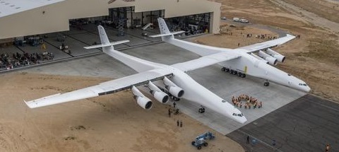
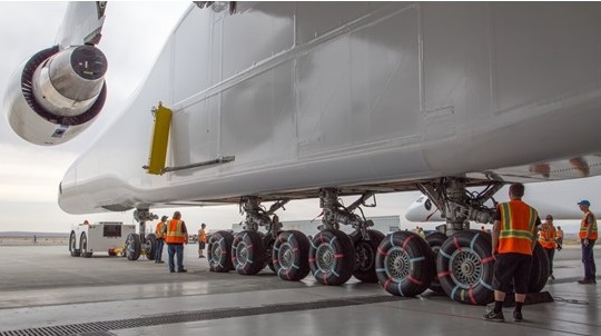
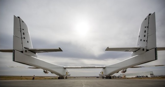
Stratolaunch has a twin-fuselage configuration, each 238 ft (73 m) long and supported by 12 main landing gear wheels and two nose gear wheels, for a total of 28 wheels. Each fuselage has its own empennage and the twin fuselages are 95 feet apart.

The pilot, co-pilot and flight engineer are accommodated in the right fuselage cockpit. The flight data systems are in the left fuselage. The unpressurized left fuselage cockpit is unmanned with storage space for up to 2,500lb of mission specific support equipment. Both fuselage cockpits are pressurized and separated by a composite pressure bulkhead from the remainder of the unpressurized vehicle.

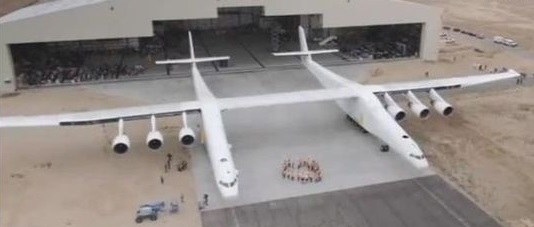
At 385 ft (117 m), it is the largest plane by wingspan, surpassing the Hughes H-4 Hercules flying boat of 321 feet (98 m). The main center section is made up of four primary composite spars supported by four secondary spars. The center section of the high-mounted, high aspect ratio wing is fitted with a Mating and Integration System (MIS), developed by Dynetics and capable of handling a 490,000 lb (220 t) load. The wing houses six main and two auxiliary fuel tanks, with the main tanks located inboard adjacent to an engine. The auxiliary tanks are located in the inboard wing where the load-carrying structure joins the fuselage.

Stratolaunch is powered by six Pratt & Whitney PW4056 engines positioned on pylons outboard of each fuselage, providing 56,750 lbf (252.4 kN) of thrust per engine. Many of the aircraft systems have been adopted from the Boeing 747-400, including the engines, avionics, flight deck, landing gear and other systems, reducing development costs.

The flight controls include 12 cable-driven ailerons powered by hydraulic actuators, split rudders, and horizontal stabilizers on twin tail units. The wing has 14 electrically signaled, hydraulically actuated trailing-edge split flaps that also act as speed brakes. The hydraulic system and actuators, electrical system, avionics, pilot controls, and flight deck are from donor B747-400s. Approximately 250,000 lb of the aircraft’s takeoff weight of 1,300,000 lb is from B747-400 components. Much of the design is based on the Boeing 747-400, replicating much of the avionics, engineering, power plants, and more to reduce the $400 million cost of the project.

Within Scaled Composites, its model number is M351. It is nicknamed “Roc” after Sinbad’s Roc, the mythical bird so big it could carry an elephant.

Initially, flights will be under an experimental certification from the FAA.

The Stratolaunch has a wingspan of 117m, it uses six 747 jet engines, sits on 28 wheels, can carry 113,400kg of fuel, and weighs 226,800kg without fuel. In order to take off, it needs about 3660m of runway.

The Stratolaunch is intended to carry a 550,000-pound (250 t) payload and has a 1,300,000-pound (590 t) maximum takeoff weight.

In December 2017, registration N351SL first low-speed taxi test took it to 25 knots (46 km/h) on the runway powered by its six turbofans to test its steering, braking, and telemetry. Higher-speed taxi tests began in 2018, reaching 40 knots (74 km/h) in February, and 78 kn (140 km/h) in October. On January 9, 2019, Stratolaunch completed a 110 knot (219 km/h) taxi test, and released a photograph of the nose landing gear lifted off the ground during the test.

In January 2019, three months after the death of Stratolaunch founder and Microsoft co-founder Paul Allen, Stratolaunch abandoned the development of its PGA rocket engines and dedicated launchers. Stratolaunch was then reported to be aiming for a first flight within a few weeks and a first launch from the carrier in 2020.

The aircraft first flew on April 13, 2019 at 06:58, at the Mojave Air and Space Port, reaching 17,000 ft (5,200 m) and 165 kn (305 km/h) in a 2 h 29 min flight. Tests included various flight control manoeuvres to calibrate speed and evaluate flight-control systems, including roll doublets, yawing manoeuvres, pushovers and pull-ups, and steady heading sideslips. Test crew Evan Thomas and Chris Guarente also flew simulated landing approach exercises at an altitude of 15,000ft.

The company ceased operations the next month, and placed all company assets, including the aircraft, for sale for US$400 million by June 2019. Cerberus Capital Management acquired Stratolaunch Systems including the Stratolaunch aircraft in October 2019. Stratolaunch announced in December 2019 that it would now be focusing on offering high-speed flight test services.

So far, only one flight has been carried out.

Model 351 Stratolaunch
Powerplant: 6 × Pratt & Whitney PW4056 turbofan, 56,750 lbf (252.4 kN) thrust each
Wingspan: 385 ft (117 m)
Length: 238 ft (73 m)
Height: 50 ft (15 m)
Empty weight: 500,000 lb (226,796 kg)
Gross weight: 750,000 lb (340,194 kg) with no external payload
Max takeoff weight: 1,300,000 lb (589,670 kg)
External payload: 550,000 lb (250,000 kg)
Maximum speed: 460 kn (530 mph, 850 km/h)
Range: 1,000 nmi (1,200 mi, 1,900 km) radius
Ferry range: 2,500 nmi (2,900 mi, 4,600 km)

SCA T-34 / Roma

Roma over Norfolk VA 1922

The Italian semi-rigid airship Roma was designed by Celestino Usuelli, the engineers Eugenio Prassone, Umberto Nobile and Colonel Gaetano Arturo Crocco. It was the first project of the Stabilimento Costruzioni Aeronautiche (“Aeronautical Construction Factory”), as the partnership of Umberto Nobile, Usuelli, Giuseppe Valle and Bennetto Croce was known. Originally designated T-34, it was designed for trans-Atlantic crossings and was the largest semi-rigid airship in the world at the tie.

As a semi-rigid design it was built about a rigid keel – though the keel was partially articulated to allow some flexibility. The passenger spaces and control cabin were within the keel. The engines, 400 hp Ansaldos, were mounted outside, angled such that the slipstreams would not interfere with each other. In addition to the 11 cells of hydrogen within its skin, it housed six cells of air, called ballonets, into which additional air could be pumped if the gasbag drooped or flattened.

It first flew in September 1920.

It was purchased by the United States from the Italian government for $250,000 in 1921. After purchase by the US, in March 1921 the Roma flew the 300 miles from Rome to Naples and back carrying the US Ambassador. After transportation to the US, Roma flew on 15 November 1921 with minor problems. When Langley crews unpacked the crated airship that August, they found its fabric skin mildewed and weakened. Six new, American-made Liberty motors, were ordered as replacements for the balky Italian powerplants.

It served in the US Army until February 21, 1922, when it crashed.

The Roma crashed in Norfolk, Virginia on February 22, 1922. The crash was caused by failure of the airship’s box rudder system, which allowed it to maneuver over tight areas. The airship contacted high voltage lines, and burst into flames. A total of 34 were killed, 8 were injured, and 3 escaped unharmed. Among the dead was the airship’s pilot, Captain Dale Mabry.

At 12:45 p.m., the preflight checks complete, 45 souls on the manifest – the crew, a few civilian mechanics, government observers – stepped aboard. The rain had stopped. The temperature had warmed to 46 degrees.
One hundred fifty men gripped lines holding the airship to earth as the Roma’s crew completed last-minute preparations for launch. The Libertys were fired up, then idled. All six worked.
Lines dropped away. The airship swept upward, tail first, then leveled.
At 500 feet, Mabry (the ship’s skipper) ordered cruising speed and, engines roaring, the Roma began making for the Chesapeake Bay. It reached it near the mouth of the Back River. Mabry ordered the ship south along the shoreline, toward Old Point Comfort. The crew waved to people below at Fort Monroe, looked down on the site of the burned Hotel Chamberlin, at crowds on the government pier. The Roma headed out over the water toward Willoughby Spit. The spit was dotted with waving Norfolkians agog at the mammoth craft overhead.
Mabry steered the Roma toward the Navy base.
After passing over the Spit and cruising over the Norfolk Naval Station, crewmembers noticed that the upper curve of the gasbag’s nose was flattening. The Roma, pitched nose-first toward the ground. From far astern came a cry: The keel was slowly buckling. Then another: The tail assembly was coming loose. The Roma began to bullet earthward at a 45-degree angle.
On the ground, sailors and civilian base workers watched the ship’s nose tilt, and warehousemen at the Army’s nearby Quartermaster Depot stepped outside to witness what was, clearly, an airship in trouble.
The skipper could see the greens and fairways of the Norfolk Country Club ahead, beyond the depot and the Lafayette River.
If they could get the Roma that far, they could put it down somewhat safely.
The passengers and crew, meanwhile, began to panic, to toss everything they could get their hands on through the keel’s windows – tools, furniture, spare engine parts. People on the ground watched a shower of equipment fall to earth.
But the Roma’s dive continued. The ground rushing to meet the falling ship was a scrubby field at the depot, split by a small road – and by a high-voltage electric line. The end came in a flash.
The Roma’s nose hit the ground, its massive girth brushed the electric line, and in an instant it was engulfed.
Its gas cells, loaded with more than a million cubic feet of hydrogen, blew to atoms.
The blast set off the ship’s gasoline tanks, creating a pyre of flame and smoke and din that leapt from the field and into the overcast sky.
Depot workers and sailors rushed to the wreckage, but the flames kept them back. Three fire companies spent five hours quelling the blaze, and watched as the Army’s greatest airship shrank to a pile of twisted aluminum that glowed red into the evening.

The event marked the greatest disaster in American aeronautics history at the time. It was the last hydrogen filled airship flown by the US military; all subsequent ships were inflated with helium.

Engines: 6 × Liberty L12, 300 kW (400 hp) each
Length: 125 m (410 ft 0 in)
Diameter: 25 m (82 ft 0 in)
Volume: 33,810 m3 (1,193,000 ft3)
Height: 92 ft
Empty weight: 34,500 kg (76,000 lb)
Useful lift: 19,100 kg (42,000 lb)
Maximum speed: 128 km/h (80 mph)

Saunders-Roe SR.45 Princess

The Saunders Roe Princess was intended as a flagship for British Overseas Airways Corporation; weighed 152 tonnes (150 tons) and was to have carried 105 passengers in its two deck, pressurized hull. The three prototypes were, ordered in May 1946, were intended for non-stop transatlantic service. The Princess was powered by ten Bristol Proteus turboprop engines. Eight of the engines coupled in pairs driving contra-rotating propellers. The flight deck crew consisted of two pilots, two flight engineers, a radio operator and a navigator. Two decks carried 105 passengers in first and tourist class. By the time the first example flew, years behind schedule, on 22 August 1952 the programme cost had nearly quadrupled to £11,000,000.

Saunders-Roe Princess Article

Meanwhile BOAC had given up flying boat operations. Instead, the boats were to be completed as long-range military transports for the RAF, but the lack of a suitable powerplant brought even these optimistic hopes to an end. Larger than the Martin Mars and heavier than the Bristol Brabazon I, the Princess prototype was flown for the first time on 22 August 1952 and spanned 66.90m with its wingtip floats retracted, weighed 156,492kg on take-off. It could attain a maximum speed of 579km/h on the power of its 10 2386kW Bristol Proteus 600 turboprop engines.

Development problems with the gearboxes of the inboard engines contributed to the decision to end development. No one wanted the Princess or her two sisterships which had been completed at Saunders -Roe’s Isle of Wight factory, and the three Princesses sat cocooned at Calshot for 15 years before the cutters’ torches finally destroyed them. The second and third Princesses did not fly.

Gallery

Saunders-Roe SR.45 Princess
Engines: 10 x Bristol Proteus 2 turboprop, 3780hp
Span: 210 ft 6 in / 66.90 m
Length: 148 ft / 45.11 m
Height: 17.37 m / 57 ft 0 in
Max take-off weight: 156500 kg / 345025 lb
Max. speed: 612 km/h / 380 mph
Cruise speed: 579 km/h / 360 mph
Range: 8484 km / 5272 miles
Pax cap: 105
Crew: 6

Potez CAMS 161

The Potez-CAMS 161 was one of three French large, six-engined flying boats intended as airliners on the North Atlantic route. The others were the Latécoère 631 and the SNCASE SE.200. In the summer of 1938, the 161’s aerodynamics had been investigated and refined with the Potez-CAMS 160, a 5/13 scale flight model.

Potez-CAMS 161 in foreground with the type 160 scale flight model behind. Floats retracted.

The 161 was an all-metal monoplane with a high, semi-cantilever wing, braced on each side by a pair of parallel struts between the lower fuselage and the wing near the first outboard engine. The engines were mounted on a constant chord central section but the outer panels were tapered, with ailerons interconnected to Handley Page slots near the wing tips. The trailing edges carried split flaps. The flying boat’s wing stabilizing floats retracted vertically to the outer engine cowlings. The tail unit was of the twin endplate fin type with the tailplane, mounted with marked dihedral, on a fuselage pedestal and externally braced from below. The D-shaped fins were fixed to the tailplane a little below their horizontal mid-lines and were also lightly braced, with struts between them and the upper tailplane surfaces.

The CAMS 161 was powered by six 664 kW (890 hp) Hispano-Suiza 12Ydrs liquid cooled V-12 engines driving three blade propellers. These were cooled via both wing surface and frontal radiators, the latter retracted after take-off. Its two step hull was flat sided forward of the wing but more rounded aft; there were long wing root fillets. Ten square windows on each side lit the passenger cabin, where twenty were provided with seating and sleeping compartments and flown and looked after by six crew.

Very different dates for the first fight appear in the literature: a contemporary report in Flight gives it as within few weeks before 7 December 1939, with “further flying tests” in the first half of 1942, whereas Hartmann has 20 March 1942 as the first flight date. In either case the CAMS machine was the first of the three to fly.

In Hartmann’s account, the March flight was from the Seine, with the aircraft in German markings. Earlier it had been painted in Air France Atlantique trim and at some point it received a French civil registration.

Full flight trials and performance measurements were never done, so the figures remain estimates, but there is clear evidence that the empty weight had increased by about 33% from the 1938 estimates by the time the 161 was flying, with a corresponding 16% increase in gross weight.

It seems to have been destroyed by enemy fire toward the end of World War II, but there is disagreement on exactly when and where: Hartmann locates the event to the Baltic, others to Lake Constance. Cuny states that the SE.200 and the Laté 631 were destroyed on the lake early in 1944, but that the Potez escaped.

Engines: 6 × Hispano-Suiza 12Ydrs, 660 kW (890 hp) each
Propellers: 3-bladed
Wingspan: 46 m (150 ft 11 in)
Wing area: 261 m2 (2,810 sq ft)
Length: 32.11 m (105 ft 4 in)
Height: 8.87 m (29 ft 1 in)
Empty weight: 17,220 kg (37,964 lb) ; Flight (1942) has 22,979 kg (50,660 lb)
Gross weight: 37,000 kg (81,571 lb) ; Flight (1942) has 43,001 kg (94,800 lb)
Fuel capacity: 15,500 kg (34,172 lb) including oil
Maximum speed: 335 km/h (208 mph; 181 kn) at 1,000 m (3,281 ft)
Cruise speed: 300 km/h (186 mph; 162 kn) at 4,000 m (13,123 ft)
Range: 6,000 km (3,728 mi; 3,240 nmi) in a 60 km/h (37 mph) wind, full load, std fuel
Crew: Six
Capacity: Twenty passengers

Potez-CAMS 160

In 1936 the design bureau of Potez-CAMS was beginning the development of the Potez-CAMS 161 six engine, trans-Atlantic passenger flying boat, intended to be a key component of Air France’s Transatlantique fleet. To test the design they built a 5/13 scale flying scale model of it, careful not just to scale dimensions of the flying surfaces and hull, but also to copy the form the nose around the cabin, engine cowlings and retractable float housings. Control surface detail and the flaps of the 161, together with its variable-pitch propellers, were included on the resulting Potez-CAMS 160. It was intended to prove both the aerodynamic and hydrodynamic behaviour of the airliner.

The 160 was a high-wing monoplane. The wing was a semi-cantilever structure, with two parallel bracing struts on each side from the lower fuselage to the wing just inside the central engines, straight-edged in plan with taper on the trailing edge only and rounded tips. It was fitted with interconnected Handley Page slots and ailerons as well as split flaps. It was powered by six four-cylinder inverted inline air-cooled Train 4T engines, each producing 30 kW (40 hp) driving three blade, variable-pitch propellers. The engines were mounted on the wing underside, housed in long, narrow cowlings intended to mimic those around the 664 kW (890 hp) Hispano-Suiza 12Ydrs water-cooled V-12 engines of the full scale aircraft.

The little flying boat had a conventional stepped hull and was stabilized on the water by a pair of floats, attached under the outboard engines and retracting into their cowlings. Its enclosed, tandem seat cockpit was shaped to reproduce the form of the 161’s nose, though the full sized aircraft had proportionally shorter glazing. The 161 had a twin fin empennage with a N-strut braced, parallel chord tailplane mounted on top of the fuselage on a short pillar with marked dihedral. The fins were of the endplate type, with curved leading edges and roughly symmetric above and below the tailplane; on each, the rudder was split into an upper and lower part. All of these features appeared on the final, full size airliner.

It flew for the first time on 20 June 1938.

The Potez-CAMS 160 appeared, after its first flight, at the 1938 Paris Aero Show.

Engines: 6 × Train 4T, 30 kW (40 hp) each
Propellers: 3-bladed variable pitch
Wingspan: 17.69 m (58 ft 0 in)
Wing area: 38.7 sq.m (417 sq ft)
Length: 12.37 m (40 ft 7 in)
Height: 3.41 m (11 ft 2 in)
Gross weight: 2,275 kg (5,016 lb)
Maximum speed: 222 km/h (138 mph; 120 kn) at 950 m (3,116 ft)
Power/mloadng: 75 W/kg (0.047 hp/lb)
Wing loading: 58.5 kg/sq.m (12.0 lb/sq ft)
Crew: Two, pilot plus observer

Porte Super-Baby / Felixstowe Fury

Porte’s ultimate design was a triplane flying boat, unofficially nicknamed the ‘Porte Super Baby’, but officially designated Felixstowe Fury. With wings spanning 37.5 m (123 ft), the Fury was powered by five 360hp Rolls Royce Eagle engines, two as tractors and three as pushers. Flying controls, initially, were power assisted by servomotors. After successful flying trials, the Fury was in the last stages of preparation for a projected flight to South Africa on August 11, 1919, when it was wrecked in Harwich harbour. All work on a second Fury was then stopped and the Fury programme cancelled. In October 1919, John Cyril Porte, the man whose inventive genius had conceived the F series of flying boats, died in Brighton of tuberculosis.

Engines: 5 x 334 hp Rolls-Royce Eagle VII
Span: 37.5 m (123 ft)
Length: 19.2 m (63 ft 2 in)
Height: 8.4 m (27 ft 6 in)
Maximum speed: 156 km/h (97 mph) at 609.5 m (2000 ft)

Opener BlackFly / BlackFly International BlackFly

The Opener BlackFly is an American electric-powered VTOL personal air vehicle designed by Canadian Marcus Leng and under development by his company, Opener, Inc of Palo Alto, California. It was publicly introduced on 12 July 2018, after nine years of development.

The first proof-of-concept version was flown on 5 October 2011, in Warkworth, Ontario, Canada, by Leng. He flew the next model, named the BlackFly, in August 2014 and then relocated the company to Palo Alto, California in September 2014. In February 2016, the second BlackFly prototype was first flown. By September 2017, the prototype had flown 10,000 mi (16,093 km) in a series of flights of at least 30 mi (48 km) each. The first pre-production aircraft was flown in October 2017.

The design is intended for the FAR 103 Ultralight Vehicles category in the US and the Basic Ultralight Aeroplane category in Canada. The US version and international versions were to have different ranges, speeds and weights to comply with national regulations. The aircraft is intended to be supplied complete and ready-to-fly.

The aircraft is made from carbon-fiber reinforced epoxy with all-electric battery-powered propulsion. It has two 13.6 ft (4.15 m) cantilevered tandem wings, on the front and rear of a short fuselage. The fuselage has a single-seat cockpit under a bubble canopy. The forward wing is low, and the rear wing high, giving the cockpit good forward visibility. Each wing has four tractor configuration contrarotating propellers powered by electric motors. The tractor configuration prevents the flexible propellers from contacting the airframe. Each wingtip has winglets to improve lateral stability and reduce vortex drag. The aircraft weighs 313 lb (142 kg) empty and can carry a pilot and baggage totaling 250 lb (113 kg). It can accommodate a pilot of up to 6.5 ft (1.98 m) in height. A ballistic parachute is optional.

The aircraft is not a tiltwing, tiltrotor or ducted-fan design. Instead, the entire aircraft changes pitch. When the aircraft is parked, both wings and their motors are canted up at about 45 degrees. To ascend vertically, the aircraft pitches up 45 degrees, so that the propellers pull vertically. The wing-mounted tractor propellers move air over the wings, reducing stall speeds. So, at pitch angles near zero degrees, the aircraft can fly slowly with high angles of attack. For efficient horizontal flight, the aircraft pitches down 45 degrees, canting the wings and propellors to an optimal angle of attack. The forward wing has a slightly lower angle of attack to aid stall recovery. At low speeds the forward wing will stall first, causing the nose to fall, increasing air speed and exiting a stall.

The take-off and landing distances are 36 inches. The landing gear consists of a rub-strip on the bottom of an amphibious hull and a small rubber bumper on the rear of the fuselage. The lower edge of the winglets are skids that limit the vehicle’s roll when parked. The vehicle is designed to fly from a grass surface, but can also be flown from fresh water, asphalt, snow and ice.

Pilot controls are a joystick with a thumb control for altitude. Flight controls are triple-redundant fly-by-wire controlling the motors and dual elevons on the outer edge of both wings. Differential motor speeds provide control authority in pitch, roll and yaw. Elevons also permit control in an efficient unpowered glide mode. The elevons are in the prop-wash of the outer propellers, enhancing their roll and pitch authority at low speeds. Flight stability is software-controlled, with modes for cruise-control, “return-home,” auto-land and geo-fencing.

Most flight testing was unmanned, operated by software with a test weight in place of a pilot. Each motor weighs 4 lb (2 kg) and produces 130 lb (59 kg) of thrust. There are two batteries per motor, located in the wing, behind each motor. Adjacent batteries can be cross-connected for redundancy. The batteries are software-monitored. Avionic include Full authority autopilot, Remote controls, and VHF airband radio.

The manufacturer claims that the design is the world’s first ultralight fixed-wing, all-electric, vertical take-off and landing aircraft. Investors in the company include Google co-founder Larry Page.

The craft was still under development in 2018.

Opener has donated a first-generation BlackFly personal ultralight aircraft to the EAA Aviation Museum in Oshkosh, Wisconsin. According to Opener, BlackFly vehicles have flown over 2,300 flights, including 900 made on preproduction models since the aircraft appeared at Oshkosh in 2018.

Opener was displaying the production version of BlackFly at the AirVenture Innovation Showcase from July 22 to July 28, 2019.

Powerplant: 8 × 112 lb thrust/engine electric motors, 42.0 hp (31.3 kW) each
Propellers: 2-bladed, 3 ft (0.91 m) diameter
Wingspan: 13 ft 7 in (4.14 m)
Length: 13 ft 5 in (4.09 m)
Height: 5 ft (1.5 m)
Empty weight: 313 lb (142 kg)
Gross weight: 563 lb (255 kg)
Fuel capacity: 12KWh
Cruise speed: 80 mph (130 km/h, 70 kn)
Range: 40 mi (64 km, 35 nmi) plus reserves
Rate of climb: 1,000 ft/min (5.1 m/s)
Rate of sink: 1,000 ft/min (5.1 m/s)
Crew: one

Onishi OS-G3

Designed and built by Mr Onishi, a Japanese sailplane pilot, the OS-G3 single-seater is powered by six model aircraft engines, mounted three on each side of the nose on a strut braced boom in line with the front of the cockpit canopy; these engines are intended to overcome the need for winch-launching or aero tows. Each 10cc OS.60 two-stroke glowplug engine drives a 12in diameter two-bladed propeller and develops 1.7hp at 14,000rpm, or 1.275hp at a less noisy 8,000rpm, the six together producing a total of 10.2hp for take-off, or 7.65hp for cruising flight. This is just enough for an unaided take-off, the take-off run being about 500ft when the OS-G3 made its first flight early in 1977. This power output leaves a 3mph margin between the cruising speed of 24mph and the stalling speed. The payload was only 154lb.

The OS-G3 is a cantilever shoulder-wing design with a swept back fin and rudder and the tailplane mounted on top; the engine slipstream is in line with the wing leading edge. There are no flaps or air brakes, and the landing gear consists of a fixed monowheel, a fixed nosewheel and a tailskid. The pilot sits under a one-piece canopy, and has six throttle levers and six cut-out switches for the engines.

Span: 46 ft 3 in
Length: 21 ft 3.5 in
Height: 5 ft 2.5 in
Wing area: 185 sqft
Aspect ratio: 11.6
Empty weight: 143 lb
Max gross weight: 297 1b
Cruising speed: 24 mph
Stalling speed: 21 mph

Northrop YB-49

The second and third YB-35 pre-production prototypes were converted into YB-35B aircraft. Their four 3250-hp (242 3-kW) Pratt & Whitney R4360 piston engines were replaced by eight 4000-lb (1814-kg) thrust Allison J35-A-5 turbojets, four jets being grouped in each trailing edge and aspirated through the same arrangement of leading-edge inlets used to supply carburation and cooling air for the piston engines of the original aircraft.

Northrop B-35 & YB-49 Article in XB-35

The YB-35B was redesignated YB-49 while it was being rebuilt, and the first aeroplane flew on 21 October 1947. The second had six 2540kg thrust Allison engines, four buried in the wings and two in underslung pods to increase the volume available for fuel.

Speed was increased dramatically from 393 to 520 mph (632 to 837 kph), but such was the thirst of the turbojets that range was halved. There were also several control problems that made the type unsuitable for use as a free-fall bomber, and it was decided to transform the type into a strategic reconnaissance aeroplane.

In June 1948 the second YB-49 was destroyed with the loss of its five man crew in a crash attributed to structural failure.

Confi¬dence ran high, and the USAF ordered 30 YRB 49s for the long-range reconnaissance role, one of which was to be built by Northrop and, because of that company’s other commitments, 29 by Consolidated Vultee. Even the fatal in flight breakup of the second prototype in March 1950 failed to dampen spirits. The RB-49 offered no real advantages over the B-47 and the new B-52, production was cancelled before the single YRB-49 flew on May 4, 1950.

The YB-35 programme continued for a while with various test airframes, but in October 1949 the whole programme was cancelled and the aircraft were scrapped. The YB 49 made a flag waving trip from Edwards Air Force Base in California to Washington, D.C. at 823 kph (511.2 mph), 160 kph (100 mph) faster than the favoured B 36, but it was too late.

Sole survivor was the six-jet YB-49A, but just four years later this was broken up.

YB-49
Engines: 8 x Allison J35-A-2, 1814 kg (4000 lb) thrust.
Engines: 8 x Allison J35-A-15, 1800kg
Max take-off weight: 96800 kg / 213409 lb
Wingspan: 52.4 m / 171 ft 11 in
Length: 16.2 m / 53 ft 2 in
Wing area: 372 sq.m / 4004.17 sq ft
Max. speed: 930 km/h / 578 mph
Range: 8700 km / 5406 miles
Range: 2800 mi / 4506 km wit 10,000 lb / 4536 kg bombload
Max bombload: 37,400 lb / 16,965 kg
Crew: 6

YRB-49
Engines: 6 x Allison J35 turbojets, 1870kg
Wingspan: 52.4 m / 171 ft 11 in
Length: 16.2 m / 53 ft 2 in
Wing area: 372 sq.m / 4004.17 sq ft

Northrop YB-49
Northrop YRB-49

North American XB-70 Valkyrie

Developed to USAF General Operational Requirement 38 for an intercontinental bomber to replace the Boeing B-52.

At one time the order was cut back to a single prototype containing no military equipment. In 1960 the US Government decided to order 12 fully operational B-70s. In March 1961, the contract awarded on 4 October 1961 was again cut back to three aeroplanes, intended mainly for research, although the third was later cancelled.

North American XB-70 Valkyrie Article

The North American XB-70 Valkyrie first flew in prototype form on 21 September 1964. When the first prototype flew it was simultaneously the longest (56.4 m/185 ft), fastest (Mach 3+), most powerful and costliest aircraft ever built, US$2000 million, and weighing 305 tonne (300 ton). Piloted by North American test pilot Alvin S. White and USAF Col. Joseph F. Cotton the first take-off took a 5000 ft ground roll and 30 seconds to get airborne. During the 65 min flight from Palmdale to Edwards Air Force Base the main wheels failed to retract and number three J93 GE engine over-revved. The aircraft flew to 16,000 ft and 375 mph. Locked rear wheels on the left main gear ground themselves down to metal on touch-down.

A delta-winged canard design, the airframe made extensive use of contemporary ‘exotic’ alloys to overcome the problems associated with kinetic heating. The wings were swept back at 65 degrees 34 minutes on the leading edge, and were covered with brazed stainless steel honeycomb panels welded together to produce an extremely strong yet heat-resistant whole. Similar construction was used for the huge rectangular moveable engine duct under the centreline, the twin vertical tail surfaces (30 ft high) and part of the fuselage. The advanced aerodynamics of this elegant yet menacing warplane were based on a large delta wing from whose centre grew a slim forward fuselage complete with canard foreplanes.

The powerplant comprised six 31,000-lb (14.062-kg) thrust General Electric YJ93-GE-3 afterburning turbojets in a 30 ft long ducted arrangement under virtually the full chord of the delta wing. To slow entering airstream from Mach 3 to less than Mach 1 the designers created a series of shock patterns which employ the vertical splitter, then additional breaks within the splitter duct. Finally hydraulically operated panels vary final throat area to meet varying conditions.

The wings outer portions were arranged to hinge downward in flight under hydraulic power to improve stability and maneuverability. An anhedral angle of 25 degrees was used for low-altitude supersonic flight, increasing to 65 degrees for high-altitude flight at Mach 3. Six power hinge actuators on each lower outer surfaces during high speed flight. Each hinge has hundreds of closely meshed gears of hard H-11 steel.

Control was provided by a combination of flaps on the canard foreplanes, no fewer than 12 wide-chord elevons across much of the trailing edge of the wings outboard of the variable-geometry engine exhausts, and large rudders on each of the vertical surfaces. The canard slab surfaces provide trim control while keeping drag low, their rear section deflecting down as flaps. Control of so complex an aerodynamic platform moving at high supersonic speeds was effected with the aid of a three-axis stability-augmentation system.

The landing gear consists of 2 tons of wheels, tires and brakes. A brake control device employs a fifth wheel on the main gear, comparing the amount of slippage between braked wheels and the fifth wheel with coefficient of friction between tires and runway surface, predicts skid point, and automatically regulates

The windshield moves along with a variable-position nose ramp. During subsonic operation the forward edge of the windshield can be lowered for better visibility. Dark spots above the cockpit area and on the canard surfaces are crane lift points.

The first prototype was flown by Alvin S. White and Colonel Joseph F. Cotton on 21 September 1964. The take-off from Palmdale runway required 5000 ft and less than 30 sec roll. During the flight the undercarriage failed to retract, one of the six engines failed, and a brake locked which burned out half of the left main gear supports. The flight was held to a maximum of 375 mph and 16,000 ft for the flight of just over one hour.

The first flight had been so long postponed and the entire project downgraded to only two prototypes. By the flight, the first US had spent $1.34 billion on its development. $92 million was then allocated to see the two prototypes through the flight program. Both XB-70’s were programmed for a 180 hr flight test schedule, including experiments for NASA. It first achieved its design speed of Mach 3 on 14 October 1965.

NASA’s Flight Research Center spent $2,000,000 on instrumentation on the No.1 aircraft. Areas of study included flutter of skin panels and internal noise levels; heating of structures in such areas as windshield, fuel tanks and crew compartment.

The improved second prototype flew on 17 July 1965, but was lost in a mid-air collision on 8 June 1966. The surviving aircraft carried out a number of test programmes, including work in connection with the US supersonic transport programme, but on 4 February 1969 it was flown to retirement at the US Air Force Museum, Wright Patterson AFB, Dayton, Ohio.

Even before the first prototype flew, however, technological developments in air defence had made the XB-70 obsolete. In 1963 the U.S. government ended the XB 70 development programme and turned the prototypes over for research purposes although one of the XB 70s was lost on 8 June 1966. The surviving XB 70 is now a museum piece.

Last Ride of the XB-70 Article

Gallery

Engines: 6 x General Electric YJ93-GE-3 afterburning turbojets, 31,000-lb (14.062-kg)
Wing span: 105 ft 0 in (32 m)
Length: 196 ft 0 in (59.74 m)
Max TO wt: 530,000 lb (240,400 kg)
Max level speed: M3 / 3218 km/h / 2000 mph
Height: 9.1 m / 29 ft 10 in
Wing area: 565.0 sq.m / 6081.60 sq ft
Ceiling: 21336 m / 70000 ft
Range w/max.fuel: 12000 km / 7457 miles
Crew: 2