Avro 698 Vulcan

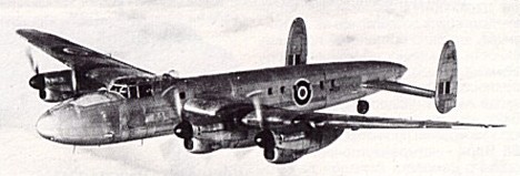
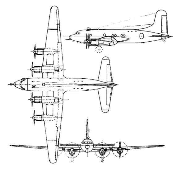
The original Avro 698 Vulcan B1 prototype was developed to Air Ministry Specification B.35/46, issued on 1 January 1947 for Britain to have nuclear bombing capability. The initial design was laid down in 1948 by Roy Chadwick, the technical director of Avro (A.V. Roe and Co. Ltd), and was preceded by the 707 series.

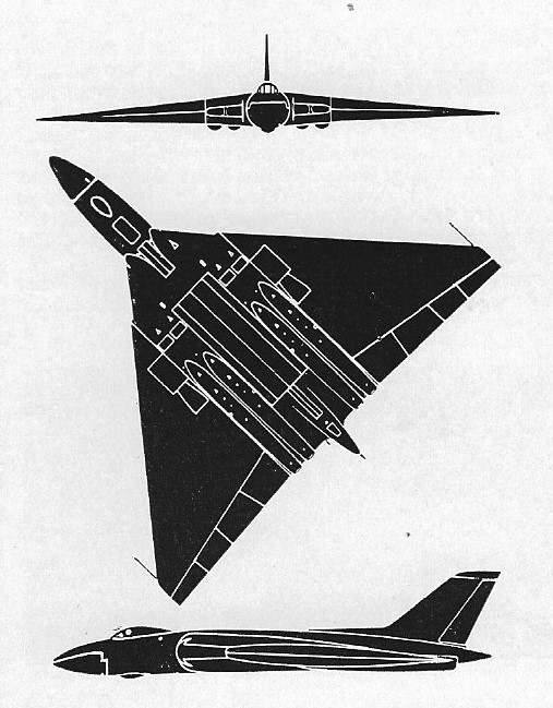
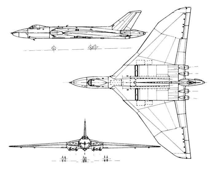
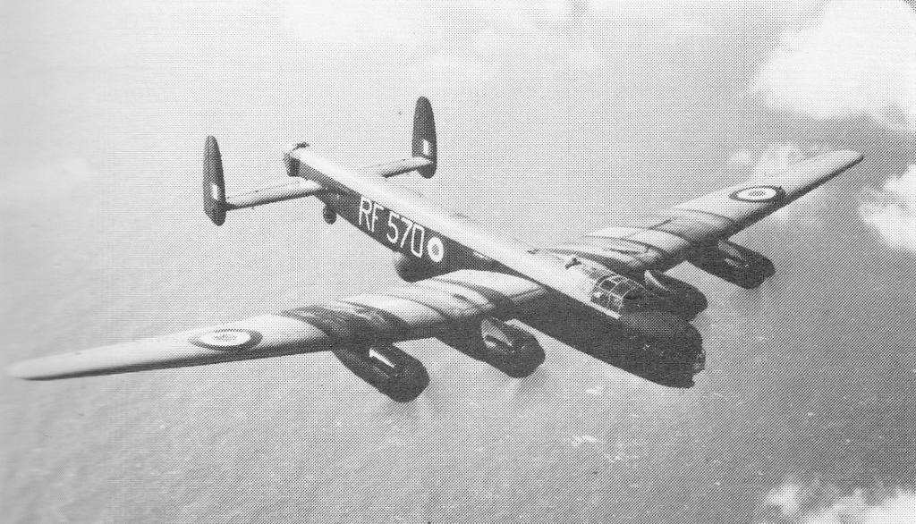
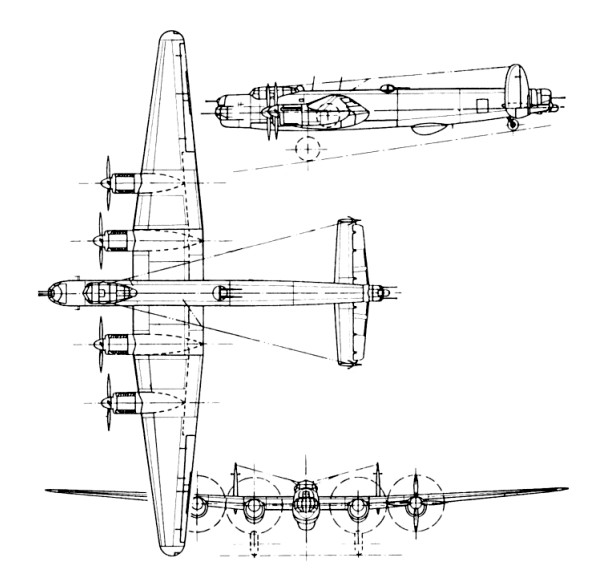
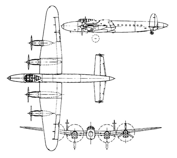
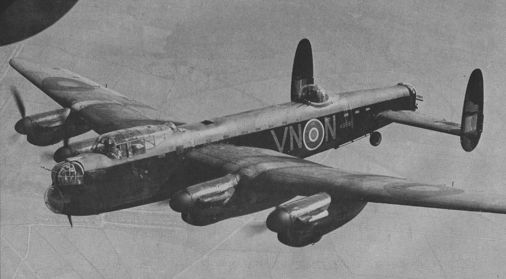
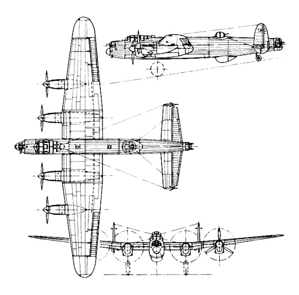
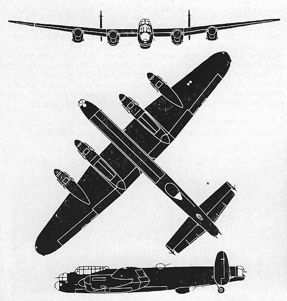
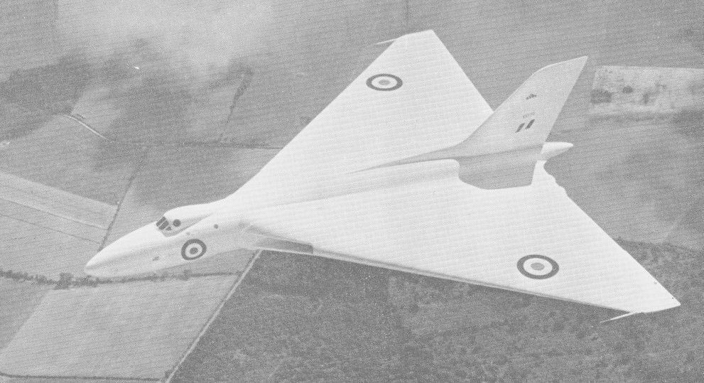
This design featured vertical tail surfaces at the extreme wingtips as opposed to a traditional tail section, offering up a great deal of surface area for improved payload, fuel load and maneuverability. The lack of a true tail section meant that, in some ways, the design was in fact a flying wing. The cockpit was positioned well forward on the fuselage, ahead of the wings and engines, and featured four engines in a staggered internal placement- two engines to a wing. The engines were to be fed by a single large rounded intake. The massive expanse of the wings would have also provided maximum space for internal armament in the form of bomb bays mounted outboard of the dual engine arrangements. Avro designated the new design Type 698 and received the British Air Ministry contract in December of 1947. Along with the Avro design, approval of the Valiant and Victor were also granted, essentially beginning the formation of the V-bomber triangle.

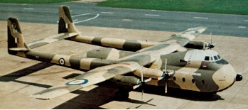
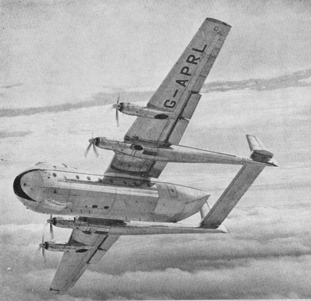
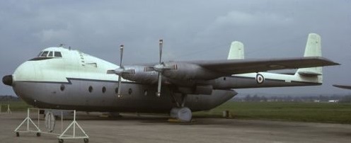
The initial Air Ministry contract called for several forms to be built including two prototypes. Along with this commitment included the construction and delivery of several flight demonstrators. The demonstrators, designated as Type 707, proved an important part of early development of the Vulcan. These development models eventually gave rise to the Type 698 prototype.

Avro Vulcan Article

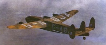
Flying for the first time on 30 August 1952, the Avro 698 prototype, VX770, had 6,500 lb.s.t. RA3 Avons, subsequent power-plants included the 8,000 lb.s.t. Sapphire, the 10,000 lb.s.t. Olympus 101s and the 20,000 lb.s.t. Olympus 301s. All four engines could be started, flight instruments aligned and powered flying controls run-up within 20 seconds. It had main qears with a total of 16 tyres, and a five seat crew compartment. A single large weapon bay was provided. The first prototype was later lost in a fatal air show accident in September of 1958.

A second prototype powered by four 10,000lb Bristol Siddeley Olympus 101 – with a slightly longer fuselage to eliminate the need for shortening the nose-wheel leg during retraction – made its first flight on 3 September 1953. Both prototypes featured a delta wing with 52 degree sweepback. The second prototype was later fitted with a “kinked” wing design that showcased differing degrees of sweepback separated into different sections of the wing leading edge. The second was later fitted with wings having a redesigned leading edge with compound sweepback and it made its first flight in this form on 5 October 1955.

Wellington, New Zealand 1959

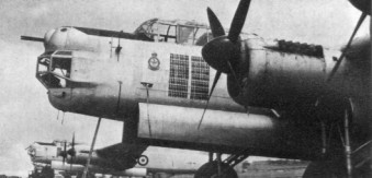
The fuselage itself was streamlined highly, with the cockpit mounted behind a nose cone assembly and just before the wing root intakes and fuselage extending well forward of the wing roots and some distance aft of the wing trailing edge. Fuel was split between either wing and a central fuselage location, all monitored in-flight by a fuel management system. The bomb bay was centrally held in the fuselage and could be fitted with additional fuel for increased range.

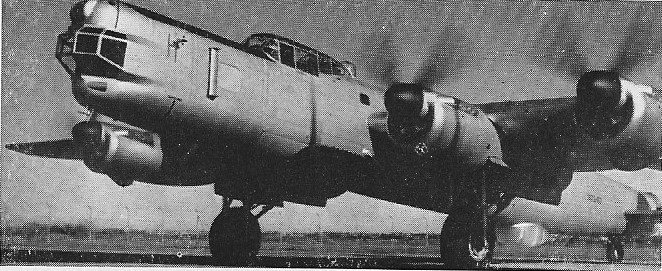
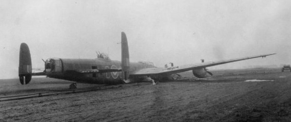
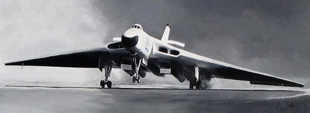
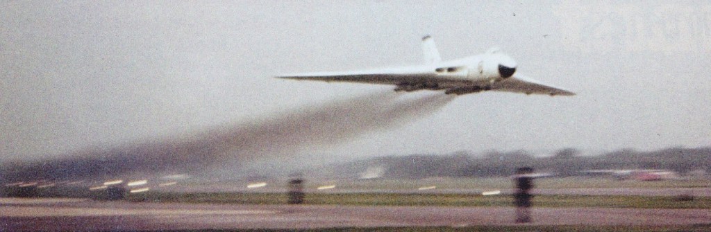
The undercarriage consisted of two main landing gears (retracting forward outboard of the engines) and a nose gear positioned behind and underneath the wingroot intakes. Each main gear was fitted with an eight-wheel bogie and retracted forwards while the nose gear and its two wheels retracted backwards. The empennage featured a single large dorsal fin extending from about the midway portion of the fuselage, with the base of the fin extending vertically out from about the extreme end point of the engines. The tail cone housed a drag chute to improve the aircraft’s landing distance.

The Avro Vulcan provided accommodation for five standard crew personnel consisting of the pilot and copilot, a systems operator, a navigator and a radar operator along with additional seating for two more. The pilot and copilot had a view out of the front of the cockpit through a five panel windscreen with framing as well as circular windows to the sides allowing for viewing to the left and right. Ejection seats were afforded to the pilot and co-pilot only – not the entire crew – they would have to bail out.

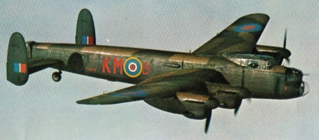
All production Vulcans were fitted with wings having the revised leading-edge configuration and the first production version was the Vulcan B.1, which entered RAF service in Febru¬ary 1957, powered by Olympus Mk 101 or Olympus Mk 102 engines of 4990 kg (11,000 lb) thrust each. All of these engines were converted later to Olympus Mk 104 standard, up¬rated in stages to 6078 kg (13,400 lb) thrust.

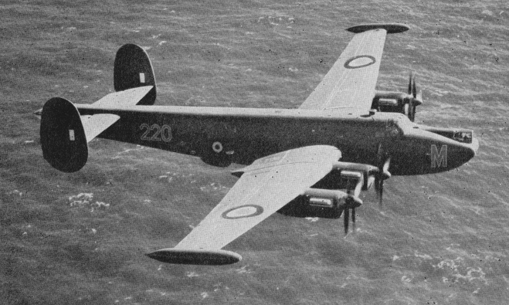
Twenty-five such machines were ordered in 1952 and the first Vulcan squadron became operational in 1957 (this delay in years was caused by yet another fatal accident). B.Mk 1’s were similar to the two prototypes. Early production models were finished the straight delta wings but these were later revised to the kinked wing design. The Mk.1s equipped Nos 83, 101 and 617 Sqn by early 1960. Nos 83 and 101 Sqns were re-equipped with Vulcan 2sband their Mk.1s were taken over by 44 and 61 Sqns.

Farnborough Air Show – September 1958 – 83 Sqn RAF Vulcan B.1

Production models were fitted with an Olympus 101 series engine of 11,000lb thrust (each). This rating was progressively uprated until reaching the Olympus 104 series with 13,500lb thrust. A total of 45 Vulcan B.Mk 1 models were eventually delivered. Re-equipment of three Bomber Command squadrons of the RAF with this version was completed in 1960.

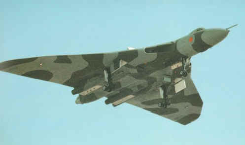
In the late 1950’s, the Vulcan B.Mk 1 had her countermeasures suite revised, becoming the Vulcan B.Mk 1A. Soviet defense technology advanced to the point that operation of the Vulcans in their originally intended mode was now in danger. As such, the aircraft was fitted with chaff dispensers, a tail warning radar (“Red Steer”), a radar warning receiver, and jammers. Twenty-eight B.Mk 1s were converted in this fashion with conversions taking place from 1959 into 1963. B.Mk1A’s and the future B.Mk 2 models were clearly discernable thanks to the addition of the ECM gear in the tail cone.

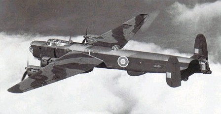
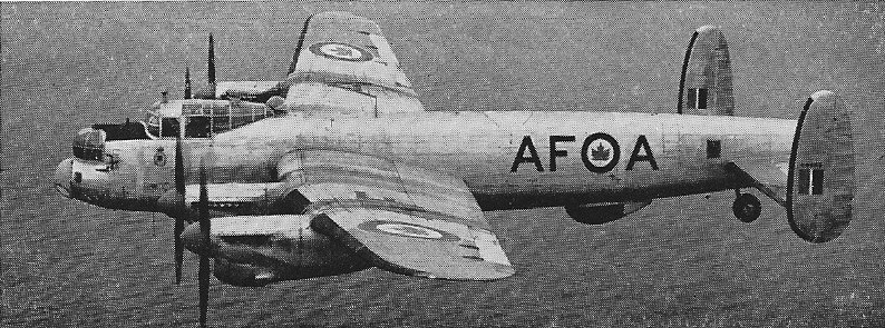
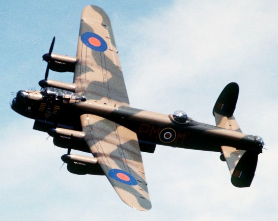
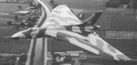
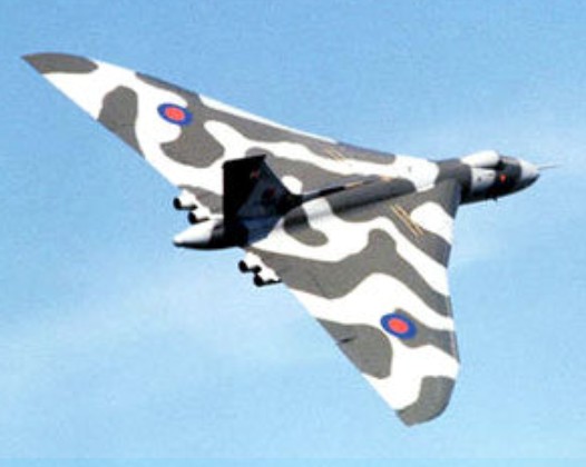
The Vulcan B.Mk 1 was followed by the Vulcan B.Mk 2 with development beginning in 1955. The system featured a revised and lengthened wing (increased from 99 feet to 111 feet), new Bristol Siddeley Olympus 201 series engines of 17,000lb thrust engines (later production models would feature the Olympus 301 at 22,000lb thrust), updated electrical system, in-flight refueling probe, a reinforced undercarriage (necessitated by the addition of the new engines), the countermeasures suite in the B.Mk 1A upgrade above and overall improvements to the aircrafts performance. First flight of the B.Mk 2 prototype occurred on August 19th, 1958 with deliveries beginning two years later and making up 89 total production examples. The increased performance offered by the Vulcan B2 made it ideal for modification to carry the Blue Steel nuclear stand-off bomb. This weapon allowed the aircraft to launch its attack from outside the immediate missile defences of a target and thereby extended the effectiveness of the Royal Air Force’s airborne deterrent.

This mark entered service in July 1960, and at first remained a high-altitude bomber. By 1961, Vulcan Mk.2s were in service with No.27, 83 and 10 Squadrons. By 1966 these had been withdrawn as the entire force had by that time switched to low level operations using conventional bombs, with a TFR (terrain following radar) on the nose.

Avro Vulcan B.2 Article

Eight B.Mk 2 models were converted to Maritime Radar Reconnaissance platforms (B.Mk 2MRR)) and 6 more were modified as in-flight refueling tankers (K.Mk 2)).

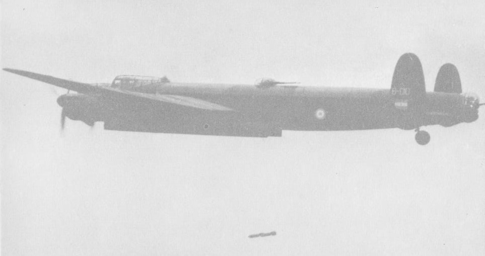
Four Vulcan SR.Mk. 2 reconnaissance aircraft served with No.27 Sqn, and the force was being run down when in April 1982 Argentine forces invaded the Falklands. Several aircraft were converted as tankers in a crash programme by British Aerospace, while others were urgently equipped with bombs, new navigation systems, flight refuelling probes, and underwing pylons for ALQ 101 ECM pods and Shrike anti radar missiles. They bombed Stanley airfield in round trips exceeding 12870km (8000 miles).
The 1964 edition did Jane’s revealed that the Vulcan B2 could cruise at Mach 0.94 at 55,000 feet. Range hi/lo was 2,300 and 1,725 miles respectively.
Vulcans served as engine test-beds for TSR-2 and Concorde.
Production was completed in 1964 and a total of 134 were built at Avro’s Woodford, Cheshire plant, along with the two Type 698 prototypes.
The Vulcan series of bombers saw limited use in combat aggression. Vulcan B.Mk 1 model bombers were sent as an intimidation factor during the Malayan Insurgency. Beyond that, they were used to showcase the types reach to the Soviet Union by conducting regular global flights to and fro. Operations with American forces and other NATO allies were a common occurrence. The only true combat actions including the Vulcan came in the 1982 Falklands War between invader Argentina and responder Britain. Vulcan B.Mk 2 bombers were used in small numbers during the conflict and succeeded in providing Britain with an intimidating force – though actual damage caused to enemy ground forces from Vulcans were minimal. Regardless, the presence of the Vulcan was no doubt on the minds of Argentine ground forces. After the war of 1982, the Vulcan’s career as a dedicated bomber was all but over. Several were converted as an interim measure to fulfill a tanker role gap while the Vickers VC10 airframes were being modified for the job. Six such Vulcan B.Mk 2 models were converted for the role and became the Vulcan K.Mk 2. These Vulcans lasted until 1984 as the VC10s came online.

The last Vulcan squadron was disbanded in March 1984.

On 18 October 2007 Vulcan B.2 XH558 flew from Bruntingthorpe in Leicestershire after a decade long restoration.

Gallery

698 Vulcan Prototype
Engines: 4 x Rolls-Royce RA3 Avon, 6,500 lb.s.t.

Avro Vulcan B Mk.I
Engine: 4 x Bristol Olympus 101, 48952 N / 4990 kg / 11,000 lb
Length: 97.113 ft / 29.6 m
Height: 26.083 ft / 7.95 m
Wingspan: 99.016 ft / 30.18 m
Wing area: 330 sq.m (3,554¬sq ft)
Max take off weight: 170032.0 lb / 77112.0 kg
Max. speed: 556 kts / 1030 km/h
Service ceiling: 55003 ft / 16765 m
Range: 2608 nm / 4830 km
Crew: 5
Armament: 9525 kg Bomb.

Vulcan B.2
Engines: 4 x Bristol Olympus, 17,000 lb.
Wing span: 99 ft 0 in (30.15 m).
Length: 97 ft 1 in (29.61 m).
Height: 26 ft 1 in (7.93 m).
Max level speed: M0.94.

Vulcan B.Mk 2
Engines: 4 x Bristol Siddeley Olympus 301 turbojet, 20,000lbs thrust
Length: 99.90ft (30.45m)
Width: 110.99ft (33.83m)
Height: 27.17ft (8.28m)
Maximum Speed: 646mph (1,040kmh; 562kts)
Maximum Range: 4,598miles (7,400km)
Service Ceiling: 55,003ft (16,765m)
Armament:
21,000 lbs internal
Accommodation: 5
Hardpoints: 0
Empty Weight: 106,000lbs (48,081kg)
Maximum Take-Off Weight: 249,122lbs (113,000kg)

Vulcan B.Mk.2A
Engines: 4 x 9072 kg (20,000 lb) thrust Bristol Siddeley Olympus 301 turbojets.
Max speed: 1043 krn/h (648 mph) at 12190 m (40,000 ft).
Service ceiling: 18290 m (60,000 ft).
Range w/max.fuel: 6400 km / 3977 miles
Empty wt: 45360 kg (100,000 lb).
MTOW: 113400 kg (250,000 lb).
Wing span: 33.83 m (111 ft 11 in).
Length (with probe): 32.16 m (105 ft 6 in).
Height: 8,28 m (27 ft 2 in).
Wing area: 368.27 sq.m (3,964,0 sq.ft).
Crew: 5
Armament: up to 21 454 kg (1,000 lb) bombs; no defensive weapons.

Vulcan B.1

Avro 696 Shackleton

The Shackleton was designed to a 1946 requirement for an all-new long-range maritime patrol aircraft for use by the Royal Air Force Coastal Command. Derived from the Avro Lincoln bomber, The Avro was initially known as the Lincoln ASR.3 and would later become known simply as Type 696 Shackleton (named after English explorer Ernest Shackleton). The Shackleton featured a similar (though all-new) fuselage design and was the first British bomber to feature contra-rotating propeller blades. First flight was achieved on March 9th, 1949.

Avro Shackleton Article

The Avro Shackleton featured a slender straight-sided fuselage with the aft end extended out past the tail plane. The tail plane also featured twin vertical fins in much the same way as that of Lincoln design. The Shackleton was also fitted with a low-wing monoplane with two engines to a wing and each engine was fitted with two three-blade propellers in a contra-rotating fashion – the first such British four-engine aircraft to do so. Power was delivered by 4 x Rolls-Royce Griffon liquid-cooled in-line engines. The Griffons were noted for requiring a great deal of attention during the aircraft’s career. The undercarriage was retractable tricycle, wth twin wheels on each unit. The main wheels retract forward into inner nacelles and the nose whels retract rearward. Armament in the Anti-Submarine Warfare (ASW) role consisted of 2 x 20mm cannons mounted in the nose while internal bombloads could consist of torpedoes, mines and bombs as needed.

The Shackleton MR.1 first flew on 9 March 1949.

Shackleton M.R.1

This entered service in April 1951 with No 120 Sqn, based in Scotland, as the Shackleton MR.Mk 1, which was soon complemented by the Shackleton MR.Mk.1A and a production run of 77 Mk.1 and Mk.lA with wider outer nacelles. The radar of the early Shackleton was inadequate, and the Shackleton MR.Mk 2, of which eight examples served with the South African Air Force, introduced a new forward fuselage which retained two 20-mm cannon but relegated the radar from a chin radome to a semi-retractable “dustbin” under the fuselage behind the bomb bay. Additionally, the MR.2 featured a reinforced undercarriage, a lengthened nose and tail section and redesigned tail planes. The first of 69 MR.2 came into use in the UK and Malta in 1952.

Issued in 1957, thirty-four Shackleton MR.Mk 3 introduced tricycle landing gear, a larger fuselage, sleeping galley for the crew on long flights, a revised wing, improved cockpit canopies, dorsal turrets deleted and wing tip-tanks (giving a 24-hour endurance) and, as a retrofit, extra power from two 2,500-lb (1,134-kg) thrust Rolls-Royce Viper Mk 203 turbojets in underwing nacelles, these being noted by their designation of MR.3 “Phase II”.

Shackleton 3

Eight were delivered to the South African Air Force. South African models were in service up until 1984.

In 1964 there were plans to install a pair of Viper 11 jets of 2500 lb thrust in wing pods to improve take-off performance of the Mk.3s.

The last model was the Shackleton AEW.Mk 2 conversion of the MR.Mk 2 for airborne early warning with APS-20 radar in a large “guppy” radome under the forward fuselage. In 1971 No 8 Squadron, RAF, re-formed at Kinloss with MR.3s. 11 remained operational in 1979 with 7 MR.3 serving in South Africa.

First flown on 28 June 1968 Nimrod MR.Mk 1s began to enter RAF service in October 1969, re¬placing the Avro Shackletons which had assumed this task towards the end of 1951.
All marks had either Griffon 57, 57a or 58’s depending upon their modification and phase level.

Shackletons saw their first real use in the Suez Crisis of 1956, the combined British, Israeli and French attack on Egypt after the Egyptian attempt to nationalize the Suez Canal.

In 1964 there were plans to install a pair of Viper 11 jets of 2500 lb thrust in wing pods to improve take-off performance of the Mk.3s.

Production totals for each model type numbered 77 for the Mk 1 series, 70 for the Mk 2 series and 34 for the Mk 3 series with a further 8 of that batch for use in the South African Air Force.

Gallery

MR.Mk 1
Engines: two Griffon 57 and two Griffon 57A.
Wingspan: 120 ft
Length: 77 ft 6 in
Height: 17 ft 6 in

MR.Mk 1A
Engines: four Griffon 57A.

MR.Mk 3
Engines: 4 x 2,455 hp Rolls Royce Griffon.

MR.Mk 2

MR.MR 3
Engines: 4 x Rolls-Royce Griffon 57A inline piston, 2,455-hp (1,831-kW)
Wing span 119 ft l0in (36.52 m)
Length 92 ft 6in (28.19m)
Height 23ft 4in (7.11 m)
Wingarea 1,421.0 sq ft (132.01 sq.m)
Empty weight 57,800 lb (26,218 kg)
Maximum take-off weight 98,000 lb (44,452 kg)
Fuel capacity: 4248 Imp.Gal
Maximum speed 302 mph (408 kph) at optimum altitude
Service ceiling 19,200 ft (5,850 m)
Range 4215 miles at 200 mph at 1500 ft
Armament: two 20-mm cannons and up to 10,000 lb (4,536 kg) of bombs
Crew 10

Engine: 4 x 4 x Rolls-Royce Griffon, 1800kW
Take-off weight: 45400 kg / 100090 lb
Wingspan: 36.8 m / 121 ft 9 in
Length: 26.6 m / 87 ft 3 in
Height: 5.3 m / 17 ft 5 in
Wing area: 132.4 sq.m / 1425.14 sq ft
Max. speed: 485 km/h / 301 mph
Cruise speed: 375 km/h / 233 mph
Range w/max.fuel: 6000 km / 3728 miles
Armament: 2 x 20mm cannons, bombs
Crew: 10

AEW.Mk 2
Engines: 4 x Rolls-Royce 57As, 2450 hp.

Avro 694 Lincoln

Originally known as the Lancaster Mk.IV, the Avro 694 Lincoln had a slightly longer fuselage, extended-span wings, a revised nose, better defensive firepower and the two-stage Merlins previously used in the high¬speed Lancaster Mk VI.

Avro 694 Lincoln Article

The Lincoln conformed to Specification B.14/43 and the first prototype flew on 9 June 1944.
Normally powered by four Rolls-Royce Merlin 85 engines with annular radiators, the Lincoln was armed with twin 12.7mm Browning machine-guns in a Boulton-Paul Type F nose turret; two 20mm Hispano Mk 4 or Mk 5 cannon in a Bristol B-17 Mk II dorsal turret; twin 12.7mm machine-guns in a Boulton Paul Type D rear turret and up to 6,350kg of bombs.

The war ended just as No. 57 Sqn, the first recipient, was equipping, and the Lincoln became the RAF’s standard post-war heavy bomber.

Avro built 168 production aircraft, plus 79 from Metropolitan-Vickers and 281 from Armstrong Whitworth. Six were also built in Canada and 54 with nose extensions in Australia by the Government Aircraft Factory at Fishermen’s Bend, NSW.

Lincoln B.30

The Lincoln B.30 is an Australian-built version for the RAAF. The first five B .30s were assembled largely from imported British components, the first flying on 17 March 1946, but a further eighty-eight were completely built in Australia, a number being fitted with a lengthened nose to accommodate two additional crew members and search radar. This increases fuselage length by 6 ft. The B.30 has four Commonwealth-built Merlin 102 engines.

Argentine Air Force Lincoln B.1

Thirty Lincolns were also diverted to the Argentine Air Force. Several versions of the bomber were produced during the production runs: Lincoln B.I with Merlin 85 engines; B.2 with Merlin 68A engines; Lincoln Mk 3 intended to be the ASR version but became the Shackleton; Lincoln B.4 with Merlin 85; Lincoln B.15 built in Canada; and Lincoln B.30 Australian version with Merlin 85 or 102 engines.
The bomber eventually equipped 20 RAF squadrons. No 97 Squadron and others were detached to Singapore in 1950 for anti-terrorist raids and to Kenya in 1954. One was converted for the bulk uplift of fuel oil and made 45 civil flights during the Berlin Airlift.

On 12 March 1953 at 14.30 hrs Soviet MiGs shot down an Avro Lincoln bomber training aircraft belonging to the RAF. According to the RAF the aircraft was within the bounds of the Hamburg-Berlin Air Corridor, just across the Soviet border, at a hight of 10,000 ft. The Soviet version of the incident stated that the Lincoln was beyond the boundaries and had penetrated 75 miles / 120 km into East Germany. Instructions to land given by the MiG fighters were replied to with machine-gun fire after which the Soviet fighters had opened fire.

ELINT Lincoln of No.192 Squadron RAF

The RAF Lincoln crashed a short distance from the West German border and six out of the seven crew members lost their lives. According to London, the aircraft, which was based at the Central Gunnery School at Leconfield, carried no ammunition, as it was on a ‘routine training flight’. From British articles at the time it could be deduced that the Lincoln crew had purposely provoked an incident in order to disclose listening posts on the ground and to gauge the reactions by aircraft of the Soviet air defences. In those days special ELINT Lincolns of the RAF, belonging to No.192 Squadron and the Central Signals Establishment at Watton, Norfolk, gatered electronic information.

Before withdrawal in 1963 one detached flight operated in Aden.
The Lincoln proved to be last piston-engined bomber to serve with the RAF.

RAAF Lincoln B.30

After seven years of operations in Malaya, the No1 Sqn RAAF returned to Australia in mid-1958, taking their Lincoln B.30s with them.

Gallery

Lincoln
Engines: 4 x Rolls-Royce “Merlin 85”, 1305kW
Take-off weight: 34020 kg / 75002 lb
Empty weight: 19690 kg / 43409 lb
Wingspan: 36.58 m / 120 ft 0 in
Length: 23.86 m / 78 ft 3 in
Height: 5.27 m / 17 ft 3 in
Wing area: 132.01 sq.m / 1420.94 sq ft
Max. speed: 475 km/h / 295 mph
Cruise speed: 345 km/h / 214 mph
Range w/max.payload: 2366 km / 1470 miles
Armament: 6 x 12.7mm machine-guns, 6350kg of bombs
Crew: 7

Avro 694 Lincoln B Mk. I
Engine: 4 x Rolls Royce Merlin 85, 1756 hp (1305 kW)
Length: 78 ft 3.5 in / 23.86 m
Height: 17 ft 3.5 in / 5.27 m
Wingspan: 120 ft 0 in / 36.58 m
Wing area: 1420.956 sq.ft / 132.01 sq.m
Max take off weight: 75014.1 lb / 34020.0 kg
Weight empty: 36792.6 lb / 16686.0 kg
Fuel capacity: 2950 Imp.Gal
Max. speed: 256 kts / 475 km/h / 295 mph at 4570 m (15,000 ft)
Cruising speed: 187 kts / 346 km/h
Service ceiling: 30495 ft / 9295 m
Cruising altitude: 20013 ft / 6100 m
Wing load: 52.89 lb/sq.ft / 258.0 kg/sq.m
Range: 2546 nm / 4715 km
Range (max. weight): 1278 nm / 2366 km
Crew: 7
Armament: nose and tail turrets each with two 12.7 mm (0.5 in) guns, dorsal turret with two 12.7 mm (0.5 in) or two 20 mm guns, and occasionally also one 12.7 mm (0.5 in) ventral hand aimed gun; bombload up to 6350 kg (14,000 lb)

Lincoln B.30
Engines: four Commonwealth-built Merlin 102
Wingspan: 120 ft
Length: 84 ft 3.5 in
Height: 17 ft 3.6 in
Loaded weight: 82,000 lb
Max speed: 290 mph
Cruise: 230 mph
Range: 3500 mi

Avro 691 Lancastrian

The first conversions of the Lancaster bomber to the high-speed long-range transport Lancastrian, were made by Victory Aircraft Ltd in Canada. Trans-Canada Air Lines operated these conversions on behalf of the Canadian government on transatlantic mail and passenger services between Montreal and Prestwick. The Canadian Lancastrians were fitted with Packard-built Rolls-Royce Merlin engines and accommodated ten passengers.

Production of the Lancastrian was later undertaken by Avro and deliveries were made to the RAF, BOAC and British South American Airways Corporation.

Gallery

Variants:
Lancastrian C.I
A nine-seat version, 23 produced for the RAF but all but two were subsequently operated by BOAC.

Lancastrian C.2
Similar to the C.I, 38 produced for the RAF.

Lancastrian 3
Initially for BSAAC, 13 passengers (18 eventually delivered, most for BOAC)

Lancastrian C.4
For RAF, eight delivered.

Lancastrian 1/C.2
Engines: 4 x Rolls-Royce Merlin T.24/2
Take-off weight: 29480 kg / 64993 lb
Empty weight: 13800 kg / 30424 lb
Wingspan: 31.09 m / 102 ft 0 in
Length: 23.42 m / 77 ft 10 in
Height: 5.94 m / 20 ft 6 in
Wing area: 120.49 sq.m / 1296.94 sq ft
Max. speed: 500 km/h / 311 mph
Cruise speed: 370 km/h / 230 mph
Ceiling: 9140 m / 30000 ft
Range w/max.fuel: 6680 km / 4151 miles

Engines: 4 x Rolls Royce Merlin XX, 1262 hp
Length: 76.772 ft / 23.4 m
Height: 19.357 ft / 5.9 m
Wingspan: 102.034 ft / 31.1 m
Wing area: 1297.062 sq.ft / 120.5 sq.m
Max take off weight: 65069.6 lb / 29510.0 kg
Weight empty: 30457.7 lb / 13813.0 kg
Max. speed: 268 kts / 496 km/h
Cruising speed: 246 kts / 456 km/h
Initial climb rate: 748.03 ft/min / 3.8 m/s
Service ceiling: 23015 ft / 7015 m
Cruising altitude: 17520 ft / 5340 m
Wing load: 50.23 lb/sq.ft / 245.0 kg/sq.m
Maximum range: 3585 nm / 6640 km
Range: 3084 nm / 5712 km
Crew: 5
Payload: 9 pax

Avro 688 Tudor / 689 Tudor           

Tudor

The original Type 688 Tudor was designed in 1943 to Specification 29/43 as a commercial conversion of the Lancaster for use over the North Atlantic as a quick replacement for the bomber-transports then being used.
As planned, the Tudor was to be a modification of the Lancaster IV (later the Lincoln) with a pressurised fuselage to carry a load of 1,705kg over 6,400km. Following the issue of the specification to Avro in March 1944 two prototypes were ordered and production contracts for BOAC (14 aircraft, plus six later) followed later in 1944 and in 1945.

When the prototype first flew on 14 June 1945 there were problems in pitch stability that required major modifications to the tail surfaces, and BOAC insisted on a further 357 modifications.

By time the first version of the Tudor was available in its production form, the BOAC requirements had altered. This, and the aircraft’s shorter than planned range, meant that the Tudor was no longer required as a passenger-carrying transport.

Although the plane received an airworthiness certificate in November 1946, BOAC recognised that it was no competitor for the Constellation already being operated across the north Atlantic by TWA and Pan Am, and BOAC cancelled its order.

Avro did sell six to British South American Airways, but before BSAA had commenced operations in 1947, the prototype Tudor 2 – designed for shorter-haul operations with more passengers – crashed, killing both test pilot and designer. Six months later, in January 1948, BSAA’s Star Tiger took off from the Azores for Bermuda and was never heard from again. The Tudor’s passenger certificate was later withdrawn after a second mysterious crash in January 1949.

The Tudor 8, powered by RR Nenes, first flew at Woodford on 6 September 1948 and flew to Boscombe Down. The Tudor 8 has the Mk.4 medium-length fuselage and structurally has been adapted to accommodate two Nenes in a single nacelle on each wing. The engines have separate tail pipes.

Aviation Traders proposed modifications for the Tudors of three types: the replacement or strengthening of any part of the equipment that could have contributed to the unexplained crashes; the effective lightening of the aircraft (by nearly a ton) by the removal of all sorts of unnecessary brackets and fittings; and the installation of up-to-date passenger facilities. Probably the most important of these many modifications was the bringing of the original Merlin 621 engines up to 623 specifications, to give increased take-off power, and the replacement of the entire landing gear with new Shackleton undercarriages. The proving flight for the first AT Tudor was on 14 February 1954. Laker could not get a War Office contract to carry troops, and was forced to devote his entire fleet of five, modified by fitting large freight doors, under the name Super Trader, to freight flights. After two fatal crashes in 1959 it was clear that the aircraft should be withdrawn.

The Tudor I was designed for only 12 passengers, but later models could carry 80. In total only 11 of the longer, wider Tudor 2, 5 and 11 models were built.

Tudor versions:
Avro 688 Tudor 1
Powered by four Rolls-Royce Merlin 102, 621 or 623 engines. Original short-fuselage Tudor for the Atlantic route, seating 12-24 passengers. First flown 14 June 1945

Avro 689 Tudor 2
Four Rolls-Royce Merlin 102 or 621 engines. The original long-fuselage version for BOAC South African and Australian routes. Accommodation for up to 60 passengers. Thirty production aircraft ordered in November 1944 and a further 49 in April 1945, plus six to be built in Australia. Order reduced to 50 in 1946 and 18 in 1948. Final 18 were to consist of two Mk 2s for development work, six Mk 5s for BSAAC – and ten modified to freighters for BOAC.

Avro 688 Tudor 3
Two additional Mk I airframes converted by Armstrong Whitworth for use as VIP transports by ministers.

Avro 688 Tudor 4
Four Rolls-Royce Merlin 621 or 623 engines. A modification of the Tudor 1 to meet BSAAC requirements. Fuselage lengthened by 1.83m and accommodation for 32 passengers. Four aircraft originally ordered. Augmented by conversion of BOAC Mk Is.

Avro 688 Tudor 4B
Two Tudor Is of BOAC contract modified to have lengthened fuselage of the Mk 4 for use by BSAAC, but retaining the flight engineer’s station as on Mk I. Accommodation for 28 passengers.

Type 689 Tudor 5
Four Rolls-Royce Merlin 621 engines. A modification of the Tudor 2, of which six were completed, five for BSAAC. Accommodation for 44 day or 36 night passengers. BSAAC aircraft delivered without passenger seats and used on Berlin Airlift. Sixth airframe converted to have four Bristol Hercules 120 engines.

Gallery

Avro 688 Tudor
Engine : 4 x Rolls Royce Merlin 100, 1613 hp
Length: 79.396 ft / 24.2 m
Height : 21.982 ft / 6.7 m
Wingspan : 120.079 ft / 36.6 m
Wing area : 1420.848 sq.ft / 132.0 sq.m
Max take off weight : 76072.5 lb / 34500.0 kg
Max. speed : 299 kt / 554 km/h
Cruising speed : 259 kt / 480 km/h
Initial climb rate : 984.25 ft/min / 5.0 m/s
Service ceiling : 31529 ft / 9610 m
Cruising altitude : 22507 ft / 6860 m
Wing load : 53.51 lb/sq.ft / 261.0 kg/sq.m
Maximum range : 4240 nm / 7852 km
Range : 4028 nm / 7460 km
Range (max. weight) : 3542 nm / 6560 km
Crew : 5
Armament : 12-24pax

Avro 689 Tudor 2
Engines: 4 x Rolls-Royce Merlin 621, 1320kW / 1,770 hp
Take-off weight: 36280 kg / 79984 lb
Empty weight: 21000 kg / 46297 lb
Wingspan: 36.58 m / 120 ft 0 in
Length: 32.18 m / 106 ft 7 in
Height: 7.39 m / 24 ft 3 in
Wing area: 132.01 sq.m / 1420.94 sq ft
Max. speed: 475 km/h / 295 mph
Cruise speed: 378 km/h / 235 mph
Ceiling: 7790 m / 25550 ft
Range: 3750 km / 2330 miles

Tudor 4B
Engines: 4 x Rolls-Royce Merlin 523, 1810 hp
Wingspan: 120 ft
Length: 85 ft 6 in
Height: 24 ft 3 in
Loaded weight: 82,000 lb
Max speed: 340 mph
Cruise: 305 mph
Range: 2800 mi

AT Tudor / Super Trader
Engines: 4 x Merlin 623.

Avro 685 York

Developed from the Lancaster bomber, the original prototype first flew in July 1942 using the wings, engines, landing gear and tail from the Lancaster. A new all-metal square-section large capacity fuselage was introduced.

Avro 685 York Article

The first prototype was converted to the one-off Mk 2 York, with Bristol Hercules radial engines; and the third prototype “Ascalon” became Churchill’s wartime transport.

Production by Avro during 1945-48 included 208 for the RAF Transport Command, and civil Yorks were built for BOAC (25), British South American Airways (12), Flota Aerea Mercante Argentina (5) and Skyways (3). One additional York was built by Victory Aircraft, Canada.

RAF and BOAC Yorks were withdrawn from service in 1957. Surplus Yorks were used by airlines in the Near East, South Africa and Canada and by the French Navy.

Gallery

Engines: 4 x Rolls-Royce Merlin XX, 954kW
Take-off weight: 31115 kg / 68597 lb
Empty weight: 19069 kg / 42040 lb
Wingspan: 31.09 m / 102 ft 0 in
Length: 23.93 m / 79 ft 6 in
Height: 5.44 m / 18 ft 10 in
Wing area: 120.42 sq.m / 1296.19 sq ft
Max. speed: 480 km/h / 298 mph
Cruise speed: 338 km/h / 210 mph
Ceiling: 7010 m / 23000 ft
Range: 4345 km / 2700 miles

Avro 685 York C Mk 1
Length : 78.511 ft / 23.93 m
Height : 17.848 ft / 5.44 m
Wingspan : 102.001 ft / 31.09 m
Wing area : 1296.954 sq.ft / 120.49 sq.m
Max take off weight : 68608.6 lb / 31115.0 kg
Weight empty : 42047.1 lb / 19069.0 kg
Max. speed : 259 kts / 480 km/h
Cruising speed : 183 kts / 338 km/h
Service ceiling : 22999 ft / 7010 m
Wing load : 52.89 lb/sq.ft / 258.0 kg/sq.m
Range : 2346 nm / 4345 km
Engine : 4 x Rolls Royce Merlin XX, 1262 hp
Crew : 4
Payload : 12-56pax / 4536kg

Engines: Rolls-Royce Merlin 24, 1620 hp
Wingspan: 102 ft
Length: 76 ft 10 in
Height: 17 ft 10 in
Empty weight: 39,458 lb
Loaded weight: 71,000 lb
Max speed: 306 mph at 10,800 ft
Cruise: 203 mph at SL
ROC: 1500 fpm

Avro 683 Lancaster

Owing to delays in the full development of the Vulture engine, the decision was taken in mid-1940 to design a new version of the Manchester with four Rolls-Royce Merlin engines. The first conversion made use of about 75 per cent of the Manchester’s parts and assemblies, the principal change being the provision of a new centre-section of the wing with mountings for Merlin engines. This aeroplane became the first prototype of the Lancaster mading its first flight on 9 January 1941. A second prototype fitted with Merlins and significantly modified in detail was designed, built and flown in just eight months.

Avro Lancaster Article

The first production Lancaster I flew just over five months later, its was powered by four 954kW Rolls-Royce Merlin XX in-line liquid-cooled engines, each driving a three-blade constant-speed and fully feathering propeller.

Lancaster I

By 1942, the Mk I was now redesignated with the more traditional B.Mk I naming convention. The system was put into full production at such a pace that the aircraft production lines were outpacing the engine lines. The American Packard company developed the same Merlin engines for shipment back to England. As further insurance, the Bristol company was in line with its own Hercules VI and XVI engines capable of 1,735 horsepower.

The Lancaster II was built with 1,229.5kW Bristol Hercules VI radial engines but only 300 Lancaster IIs were built.
The first of Bomber Command’s squadrons to be equipped with the Lancaster was No 44 based at Waddington, Lincs, in early 1942. No 44 used them operationally for the first time on 3 March 1942 laying mines in the Heligoland Bight.
Improving engines provided improving performance: the Lancaster VII, with 1,207kW Merlin 24 engines, had a maximum take-off weight of 30,844kg by comparison with the 22,680kg of the early Lancaster I. The bomb bay was modified progressively to carry the 9,980kg Grand Slam bomb.
Six major companies built 7377 aircraft at ten factories on two continents; at the height of production over 1,100,000 men and women were employed working for over 920 companies.

The Lancaster operations included the breaching of the Mohne and Eder dams on the night of 16-17 May 1943 by No 617 Squadron (led by Wing Cdr Guy Gibson); and the sinking of the German battleship Tirpitz.

Lancaster Dam Buster Article

During World War II 608,612 tons of bombs were delivered in 1156,000 sorties, which represented two-thirds of the total bomb load dropped by the RAF from March 1942 to May 1945. At wars end there were 56 squadrons of Lancasters in RAF Bomber Command.

1944 at Friskerton

On average Lancasters completed twenty-one missions before being lost.
From 1951 until early 1953, France took delivery of 54 reconditioned Lancasters for maritime patrol, general reconnaissance and search and rescue (SAR) work 32 Mk Is and 22 Mk VIIs.
In all 13 French Lancasters were destroyed in accidents, or struck off charge following damage. The bulk of the fleet was withdrawn and scrapped with the arrival in strength of the Neptunes in 1958 1959. Others served on with the surviving Escadrilles de Servitude until 1961 1962.
It fell to 9S in New Caledonia to be the last French unit to operate Lancasters, giving them up operationally in 1964, ferrying the last two to preservation in April (No 13) and August (No 15) that year.
In Canada, 408 Squadron, RCAF, withdrew its last Mk X examples in March 1964 at Rockcliffe.

Lancaster 10-MR

Victory Aircraft in Malton (Toronto), Ontario, produced over 400 Lancaster Mk X’s. The basic aircraft built in Canada was the Lancaster 10-B. Eight were converted for photo-reconnaissance as Lancaster 10-Ps in 1948, and others were converted to Lancaster 10-ASR (Air-sea rescue) and 10-BR (Bomber-reconnaissance) during 1949-50. The Lancaster 10-MR maritime reconnaissance aircraft succeeded the 10-BR, the first conversion flying on 29 December 1950.

Lancaster on Tour 1946 Article

Of the 7366 Lancasters built, all but 300 radial engines Mk.IIs had Merlin engines of 1460-1640 hp. All carried a crew of seven. 3487 were lost on operations over Germany during WW2.

Gallery

Avro Lancaster I
Engines: 4 x Rolls-Royce Merlin XX, 1280 hp(955 kW) or Rolls-Royce Merlin 22, 1460 hp(1089 kW) or Rolls-Royce Merlin 24, 1640 hp(1223 kW)
Wing span: 31.09m
Length: 21.18m
Height: 6.25m
Wing area: 120.49sq.m
Empty eight: 16,783 kg
MTOW: 30,845 kg
Max speed: 44s kph @ 4570m
Range: 4072 km
Armament: 9 x 7.7 mm Browning mg
Bombload: 9979 kg

Avro 683 Lancaster Mk I
Engine: 4 x Rolls Royce Merlin XXIV, 1618 hp
Length: 69.488 ft / 21.18 m
Height: 20.013 ft / 6.1 m
Wingspan: 102.001 ft / 31.09 m
Wing area: 1296.954 sq.ft / 120.49 sq.m
Max take off weight: 70013.2 lb / 31752.0 kg
Weight empty: 36907.3 lb / 16738.0 kg
Max. speed: 249 kts / 462 km/h
Cruising speed: 183 kts / 338 km/h
Service ceiling: 24606 ft / 7500 m
Cruising altitude: 20013 ft / 6100 m
Wing load: 54.12 lb/sq.ft / 264.0 kg/sq.m
Range w/max.fuel: 3600 km / 2237 miles
Range w/max.payload: 1800 km / 1118 miles
Range with 14,000 lb. (6,350 kg.) of bombs: 660 miles (2,700 km.).
Crew: 7
Armament: 10x MG 7,7mm, 8185 kg Bombs

Lancaster II
Engines: 4 x Bristol Hercules. Length: 70ft.

Lancaster III
Length: 69 ft 6 in
Wingspan: 102 ft
Top speed: 275 mph
Armament: 8-10 x .303 mg
Bomload: 18,000 lb
Crew: 7
Range: 2530 miles

Lancaster X
Type 7 Seat Heavy Bomber
Engines: 4 x Rolls Royce Merlin 224, 1620 hp
Wing Span: 102 ft (31.1 m)
Length: 69ft 6″ (21.1 m) “
Height: 20ft 4″ (6.2 m)
Speed: 272 Mph (438km/h)
Armament: Nose and Dorsal Turrets with two 0.303in Brownings, tail turret four 0.303in Brownings. Bombs-14,000lbs – 22,000lbs with modification

683 Lancaster 10-MR
Engines: 4 x Rolls Royce Merlin 224, 1620 hp
Empty weight: 41,000 lb
Loaded weight: 68,000 lb
Max speed: 250 mph
Cruise: 216 mph
Range: 2250 mi
Wingspan: 102 ft
Length: 68 ft 10 in
Height: 20 ft
Wing area: 1297 sq.ft

Lancaster 10-MR

Aviation Trader ATL.98 Carvair

At Laker’s suggestion, A. C. Leftley, chief designer of Aviation Traders, designed a nose-loading car ferry conversion of the Douglas DC-4/C-54 after investigating a variety of other types as potential car ferries. With second-hand DC-4s and C-54s available for £40,000 and conversion costs of around £150,000 the Carvair (Car-via-air) was significantly cheaper than any new design. A new bulbous nose was fitted, with a much ¬raised cockpit. All the controls, most of which were mechanical, had to be re-routed from the new flight deck, but the ATL-98 Carvair, as it came to be known, proved easy to fly, and the bulbous nose reduced its speed by only four knots. The tail surfaces were increased in size to match those of the DC-7. DC-6 brakes were fitted to cope with the higher all-up weight of the Carvair, which could carry five full-size saloon cars and 23 passengers.

Aviation Trader ATL.98 Carvair Article

The prototype Carvair was based on an Air Charter DC-4 and first flew on 21 June 1961. Conversions of DC-4s lasted for eight years, from 1960 to 1968, and they continued to fly for British Air Ferries until 1 January 1977. Twenty-one Carvairs were eventually produced.

Nationwide Air, Nelson, New Zealand, circa 1979

Gallery

Powerplant: 4 x Pratt & Whitney R2000-7M2, 1450 shp take-off power 2700 rpm
Props: Hamilton Standard 3 blade 13 ft 1 in diameter
Span, 117 ft 6 in
Length, 102 ft 7 in
Height, 29 ft 10 in
Gross wing area, 1 462 sq.ft
Max. usable floor area, 665 sq.ft
Max. usable cabin volume, 4 630 cu.ft
Max. cabin length, 80 ft 2 in
Max. width, 9 ft 8 in
Max. height 6 ft 9 in.
Accommodation: 22 passengers in rear cabin or all-passenger version 85.
Basic operational, 42,465 lb
Total fuel, 17 208 lb
Max. take-off; 73 800 lb
Max. landing weight: 64,170 lb
Max. payload (weight limited), 18,035 lb
Max. zero fuel, 60,500 lb
Power loading (max. take-off weight), 12.7 lb/shp
Wing loading (max. take-off weight), 50.5 lb/sq.ft
Wing loading (max. landing weight) 43.9 lb/sq.ft
High-speed cruise, 191 kt. at 10,000 ft
Long-range -cruise, 175 kt. at 10,000 ft
Approach speed, 93 kt
Balanced field length, ISA at sea level, 4,200 ft
Landing field length, ISA at sea level, 4,470 ft
Range with no reserves, max. fuel, 14,867 lb payload, 3000 nm

AVIC AG600 / TA-600 / Kunlong

The AVIC AG600, code named Kunlong (鲲龙), also known as TA-600, is one of China’s three “big plane projects” approved by the State Council of China in 2009, along with the Xi’an Y-20 and C919. It is intended for both civil and military roles. In civil use, as an aerial firefighter it will be capable of dropping 12 tonnes of water, while in search and rescue operations it will accommodate up to 50 passengers. It is also intended to meet China’s strategic defence needs in the South China Sea area.

It was designed by the Aviation Industry Corporation of China (AVIC). The aircraft was developed by a group of 70 aircraft component manufacturers and research teams in association with more than 150 institutes across 20 provinces and municipalities in China. Over the years, its silhouette has been slowly revised by way of modified float supports, a more blended, better-contoured cockpit roofline, and a “T-style” tail unit (as opposed to the split vertical tail fins of the SH-5). On the whole, the aircraft has continued use of flying boat basics – high, shoulder-mounted wings, two engines installed at each wing, and a boat-like hull for water landings. The hold will also support seating for up to 50 passengers. The resulting aircraft has proven heavier than previously planned at approximately 107,000lb, up from the original 98,000lb. The added weight has altered the expected operational range, reduced from 3,200 miles to 3,100 miles. The AVIC AG600 is an amphibious aircraft having the hull of a flying boat for waterborne operations along with a wheeled retractable undercarriage for alighting on land. The prototype AG600, built by CAIGA, has a wingspan of 38.8 metres (127 ft) and is powered by four turboprop engines. The type of engine is WJ-6, a modified Chinese-made version of the Soviet Union’s Ivchenko AI-20 series. It is designed to have a maximum takeoff weight of 53.5 t (118,000 lb) and a maximum range of over 5,000 km (3,100 mi).

The aircraft is powered by four Chinese-made WJ-6 turboprop engines driving four six-bladed constant speed propellers. WJ-6 is a license-built copy of the Ivchenko AI-20 engine and generates a power output of 3,805kW (5,103hp).

The mid and forward fuselage sections of the aircraft were completed in December 2014 and March 2015 respectively. The horizontal and vertical tail was completed by January 2016. The prototype was rolled out on 23 July 2016 at the Zhuhai AVIC factory. Its maiden flight was made from the runway of Jinwan Civil Aviation Airport in Zhuhai, Guangdong on 24 December 2017, at 09:39 China Standard Time. 17 orders had been received from Chinese customers before the flight.

On March 2, 2025, China announced that the AG600, the country’s domestically developed large amphibious seaplane, has successfully completed its flight testing phase and is on the verge of receiving its type certificate from the Civil Aviation Administration of China (CAAC).

According to a statement from the Aviation Industry Corporation of China (AVIC), the state-owned aerospace giant overseeing the aircraft’s development, the AG600 prototype conducted its final flight test on the morning of Friday, March 1, 2025, at a civil aviation testing center in Pucheng, located in Shaanxi Province. This successful flight concludes a two-year testing program, which saw the aircraft complete a total of 2,014 flights spanning 3,560 hours.

The AG600 program was officially approved by the Chinese government in June 2009, with research and development kicking off later that year. The program saw the collaboration of tens of thousands of engineers and researchers from over 160 domestic institutes, enterprises, and universities. The first prototype of the AG600 was constructed in 2014 and completed in July 2016. After its debut flight in December 2017 at Zhuhai in Guangdong Province, the aircraft has undergone extensive testing across various regions of China.

The aircraft can take-off and land from 1,500m-long, 200m-wide and 2.5m-deep water. It has the capacity to collect 12t of water in 20 seconds and can carry up to 370t of water on a single tank of fuel. The AG600 can perform take-off and landing in severe weather conditions with a wave height of 2m. The maximum take-off weight of the aircraft is 53.5t on runways and 49t on water.

AG600 aircraft received two option orders at the 10th Airshow China held in Zhuhai in November 2014, bringing the total option orders to 17.

AG600
Engines: 4 × WJ-6 turboprops, 3,805 kW (5,103 hp) each
Propellers: 6-bladed constant speed
Wingspan: 38.8 m (127 ft 4 in)
Length: 36.9 m (121 ft 1 in)
Height: 12.1 m (39 ft 8 in)
Max takeoff weight: 53,500 kg (117,947 lb)
Maximum speed: 570 km/h (354 mph; 308 kn)
Cruise: 500 kph
Stall: 220 kph
Range: 4,500 km (3,418 mi; 2,970 nmi)
Service ceiling: 10,500 m (34,400 ft)
Capacity: 50 passengers

Armstrong Whitworth AW.650 / AW.660 Argosy

AW660 Argogy C.1

Designed by Armstrong Whitworth later incorporated into Hawker Siddeley Group, the first prototype flew on January 8, 1959.

In order to shorten development time, Armstrong Whitworth put in hand a batch of ten of their Argosy Freighters, without waiting for firm orders. The second of these flew on 8 January 1959. Orders were received from Riddle Airlines and for a military version by RAF Transport Command.

Armstrong Whitworth AW.650 Argosy Article

The private venture Argosy completed flight trials during 1960. The first operators were to be Trans-Arabia Airlines and Riddle Airlines.

The series 100 led to the military Armstrong-Whitworth (later WhitworthGloster and Hawker-Siddeley) AW660 Argosy derived from the civil AW650, major design changes involving a “beaver tail” for air para-dropping, fixed nose doors, heavier and strengthened floor, Smith’s military flight system, Ekco weather radar-the scanner housing providing the characteristic bump on the nose and other internal equipment changes. Twenty aircraft (XN814-821, XN847-858) were ordered in January 1959 to replace the last of the Valettas, and a manufacturer’s prototype, G-APRL, was first flown on July 28, 1960, with some of the military modifications including the beaver tail doors. Follow-on production orders were placed for a further 36 aircraft (XP408-413, XP437-450, XR105-109, XR133-143), while the first RAF Argosy C1 (XN814) was flown for the first time on March 4, 1961. Together with the second aircraft it soon passed to the A&AEE at Boscombe Down for service trials prior to entry into service.

AW.660 prototype G-APRL

The variety of roles adopted by the Argosy are very wide-it can carry 54 fully-equipped paratroops (with two despatchers and one additional loadmaster); or two Ferret scout cars/ Land Rovers plus 20 troops in the air-transport role; or 64 passengers (with two air quartermasters); or 48 stretcher patients (with four attendants and two AQMs) for casevac. As a tactical support aircraft it can deliver nine x one ton containers or two medium-stressed platforms (12 0001b each). In the photographic role F-117B cameras can be installed, and for air-sea rescue Lindholme containers and flares are carried.

In the mid-1960s the first four operational squadrons (105, 114, 215 and 267) were active in the Far East, Gulf and European theatres.

RAF Argosy XP409

An early attempt to offset the problems of short range was tried with XN819 early in 1962 when in-flight refuelling equipment was fitted. However, after trials at the A&AEE Boscombe Down, it was decided not to proceed with the modification programme.
In the internal-security fit in 1963 XN814 was modified to accommodate external bomb racks (for 14 bombs) on each side of the lower fuselage; the nose window was equipped as a bomb aimer’s position. After successful trials with the “Argi-bomber” the aircraft used in Aden and the Far East were given this modification. There is no evidence that they were operationally used in this offensive role.
The C and E Mk.1 aircraft had higher gross weights and more powerful engines than the 222. Fifty six were used by the RAF.
With the delivery to the RAF of the Hercules it was announced in 1968 that the Argosy would be withdrawn from tactical transport duties by 1970. However the fuel tank corrosion problems encountered by the Hercules and the subsequent withdrawal of aircraft for modification meant that this target date could not be reached.
The 660 had the ‘Shackleton Wing’ and had ‘clam-shell’ doors at the rear of the fuselage to allow air-dropping of stores. Unlike the civil 650, the nose was fixed. The early versions of the civil AW 650 also had the ‘safe life’ Shackleton wing. It was main spar failure that curtailed the fatigue life of the AW 650/660 aircraft. However later versions known as AW 650 200 were manufactured with a ‘fail safe’ wing of much more modern structural philosophy. The series 200 can be recognised as it is fitted with large wing fences.
The 222 model was designed to the specifications of British European Airways, and began service in 1965. The 200 Series featured a redesigned box-spar increasing the MAUW and fuel capacity. Only 17 civilian Argoseys were built.

Gallery

Argosy series 100
Engines: 4 x Rolls-Royce Dart 526 turbo-prop, 1506kW
Take-off weight: 39916 kg / 88000 lb
Empty weight: 20865 kg / 46000 lb
Max payload: 28,000 lbs.
Wingspan: 35.05 m / 114 ft 12 in
Length: 26.44 m / 86 ft 9 in
Height: 8.23 m / 27 ft 0 in
Wing area: 15.45 sq.m / 166.30 sq ft
Cruise speed: 451 km/h / 280 mph
Ceiling: 6100 m / 20000 ft
Range: 3219 km / 2000 miles
Crew: 2-3
Passengers: 84

AW650-222
Cruise: 240 kts.
No built: 7.
Max payload: 31,000 lbs.
MAUW: 93,000 lbs.
Max range: 1600 nm.
Approach speed: 108 kts.

Hawker Siddeley / Armstrong Whitworth AW 650 Argosy C
Heavy transport aircraft, United Kingdom, 1961
Length: 89.173 ft / 27.18 m
Wingspan : 114.993 ft / 35.05 m
Max take off weight : 103017.6 lb / 46720.0 kg
Max. speed : 233 kts / 431 km/h
Service ceiling : 20013 ft / 6100 m
Range : 300 nm / 555 km
Engine : 4 x RollsRoyce Dart RDa 8 Mk 101, 2680 shp
Crew : 3+69

Argosy C1
Engines: 4 x Rolls-Royce Dart RDa8 Mk102 turboprops, 2210 shp (dry) or 2470 shp (with water-methanol injection).
MAUW: 97 000 lb.
Cruise: 220kt @ 10000-20000ft.
Max payload / range: 24600 lb over 180 nm.
Max range/payload: 1700nm with 3500 lb.
Radius of action/payload: 750nm with 5000 lb.