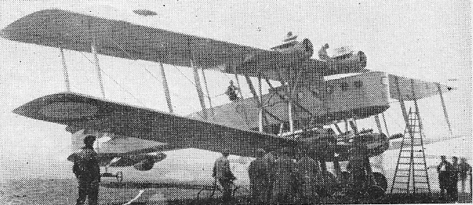
1918 bomber.
The Bleriot 75 was a transport development.
Engines: 4 x 300 hp Hispano-Suiza
Wingspan: 98 ft 6 in
Wing area: 4066 sq.ft
Length: 72 ft 2 in
Loaded weight: 28,000 lb
Max speed: 83 mph
Endurance: 5 hr
1918 bomber.
The Bleriot 75 was a transport development.
Engines: 4 x 300 hp Hispano-Suiza
Wingspan: 98 ft 6 in
Wing area: 4066 sq.ft
Length: 72 ft 2 in
Loaded weight: 28,000 lb
Max speed: 83 mph
Endurance: 5 hr
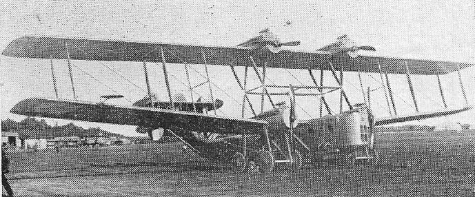
1918 bomber.
Engines: 4 x 300 hp Hispano-Suiza
Wingspan: 98 ft 6 in
Wing area: 4066 sq.ft
Length: 72 ft 2 in
Loaded weight: 28,000 lb
Max speed: 83 mph
Endurance: 5 hr
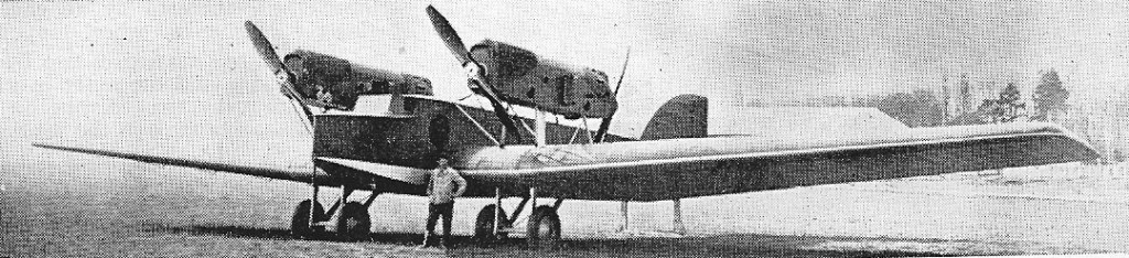
Believed to be the transatlantic flight monoplane specially built for Louis Bleriot’s son before he was killed, the 1920s Bleriot 195 was a mail/freight, cantilever monoplane
Engines: 4 x Hispano-Suiza 8A, 250 hp
Wingspan: 70 ft 10 in
Length: 44 ft 10 in
AUW: 18,000 lb
Max speed: 130 mph

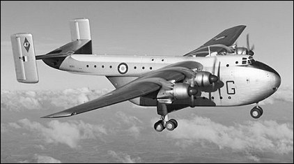
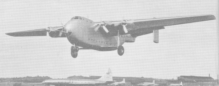
General Aircraft Ltd was asked to build a prototype of its submission for C.3/46; the aircraft was designated GAL‑60 and based on the Hamilcar cargo glider built by General Aircraft, and named Universal Freighter in recognition of its civil and military potential. Work began at Feltham on the contracted prototype, and on a number of long‑lead items for an anticipated second aircraft. During 1948, discussions between General Aircraft Ltd and the Humberside firm of Blackburns led to a merger of the two companies under the joint name of Blackburn & General Aircraft Ltd. The new company was formed on 1 January 1949 and it was proposed that all work in progress at the various factories be completed as originally planned; assembly of the half‑finished Universal prototype was therefore continued at Feltham and work proceeded normally until its completion in October of that year. Only then was decided that Hanworth Aerodrome adjoining the Feltharn premises ‑ was totally unsuitable for the first flight of sue a massive aeroplane. As a result of this discovery, the whole thing was taken apart again and loaded on to lorries for the journey to Brough, where it was reassembled after considerable difficulty, and successfully flown as WF320 on 20 June 1950.
Blackburn B.101 Beverley Article

The aircraft was a big one; 28 tons of metal built on almost architectural principles concealed a main freight hold 36ft long, 15.5ft high and 10ft wide. The forward hold underneath the flight deck was 15ft long, with a headroom of nearly 7ft, and the tail boom provided a rabbit warren of individual compartments sloping down towards the main hold and punctuated by structural frames. The 162ft wing stood over 20ft from the ground and the tailplane span was 42ft. The single mainwheel tyres were over 6.5ft in diameter.
The aircraft was designed for a rough field environment, and the possibility of battle damage had been considered from the outset. At any time it could be called away from a convenient airfield servicing unit and flown into primitive, and perhaps hostile, areas with minimal maintenance facilities. Everything had to be kept as simple as possible: no pressurisation, no pneumatics, no retractable undercarriage or fancy structural techniques that could fall apart under the considerable stress of rough field operations at gross weights in excess of 100,000 lb.
Part of Spec C.3/46 called for a service ceiling of 18,000ft. This led to discussions with the Engine Division of The Bristol Aeroplane Company which agreed to develop a special Hercules unit with a two–speed supercharger and other refinements that would push its take off power to 2,040hp at 2,800rpm. The engines were mounted as self contained, un handed powerplants that were fully interchange¬able, each driving a 14ft diameter Rotol constant-speed propeller with feathering and reverse pitch facilities.

After the successful first flight, the company’s chief test pilot, ‘Tim’ Wood who had originally been with General Aircraft Ltd set about the initial handling trials with D. G. Brade as his co pilot. The simplicity of construction and the overall soundness of the design, made it possible to complete all the essential clearances in 21 flights.
The anticipated second prototype was ordered at the 1950 SBAC display, where WF320 had made every other exhibit look tiny. The new aircraft was to be significantly re designed around four 2,850hp Bristol Centaurus engines: the rear fuselage shape would be altered to accommodate removable clamshell doors and the tail boom would be enlarged and structurally re designed to provide seating for up to 42 passengers. At this time the manufacturers were still hopeful of civil sales and were quoting a fly away price of just under £400,000.
For nearly 18 months the first aircraft was used on a series of trials. The loading ramp and rear doors were removed, and the single mainwheels were replaced by four-wheel boogie units. Structural considerations prevented full modification of the tailboom but heavy dropping was done to look at possible load exit problems and aircraft trim changes during violent centre of gravity movement.
Permission to go ahead with construction of the second machine was given during the Spring of 1952. Although the new aircraft amounted to a major redesign of the original Universal Freighter, it was completed in 15 months. Many of the heavy components that were made at Feltharn during 1948 49, particularly for the wing and centre fuselage were virtually unchanged and could almost be used from stock, The Universal Mk2 (WZ889) made an uneventful first flight from Brough on 14 June 1953.
In September 1952 the Air Ministry, which was by then satisfied with the final re design, gave approval for an initial batch of 20 for the RAF under the type name Beverley CMkl. Production began almost immediately, with work being shared between the company’s factories at Dumbarton and Brough. Most of the important sub assemblies were manufactured at Dumbarton and then taken by road to the aircraft production line at Brough. By the time the first machine was recognisable as a Beverley under construction, the RAF’s commitment to the type had jumped to 47.
The second batch was ordered during May 1954 and it guaranteed continuous production until the summer of 1958.
The first two production Beverleys (X13259 and XB260) were flown during January and March 1955: they were retained for some time as development machines, as were the second pair (XB261 and XB262), both of which were delivered to Boscombe Down in July 1955 for the usual acceptance, handling and flight limitations programme. Squadron life for the Beverley began on 12 March 1956, when XB265 was delivered to the Abingdon based No 47 Squadron. By May 1958, three other squadrons (Nos 53, 30 and 84) had re equipped with the air¬craft, and a flight of four machines was attached to No 48 Squadron in Singapore. This flight was later to receive another aircraft and achieve full squadron status (as No 34 Squadron) in March 1959.

The aircraft’s withdrawal front the RAF took place in 1967 68 at the time of the RAF’s acquisition of the Lockheed C 130K Hercules.
The last Blackburn B-101 Beverley, XB259 had been part of the display at Fort Paull, a former gun battery and heritage centre on the Humber, since 2003 but the site’s closure threatened its future.
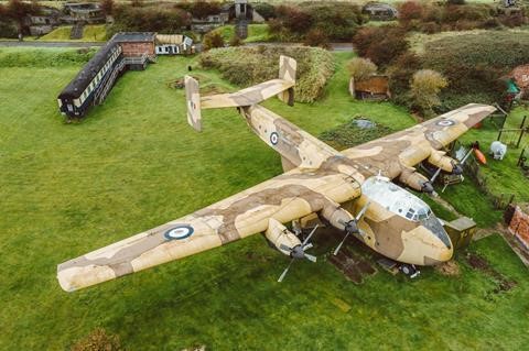
Forty-six years after its final flight Martyn Wiseman, managing director of Condor Aviation, with an anonymous colleague bought the four-engined Bristol Centaurus-powered aircraft, and needed to raise £100,000 ($132,000) to dismantle it and carry it to its new home, where it will be the center-piece of a larger exhibit at Birchwood Lodge, a private airfield in Yorkshire, close to the original factory.
Blackburn Beverley C.1
Engines: 4 x Bristol Centaurus 173
Wingspan 162 ft
Length 99 ft 2 in
Mauw 135,000 lb
Max speed: 238 mph at 5700 ft
Blackburn B-101 Beverly C.1
Engines: 4 x Bristol “Centaurus” 273, 2125kW, 2811 hp
Max Take-off weight: 64864 kg / 143001 lb
Empty weight: 35940 kg / 79235 lb
Hold capacity: 6,000 cu.ft
Payload: 22400kg / 49384 lb or 94 troops or 70 paratroopers
Wingspan: 49.38 m / 162 ft 0 in
Length: 30.3 m / 99 ft 5 in
Height: 11.81 m / 38 ft 9 in
Wing area: 270.9 sq.m / 2915.94 sq ft
Max. speed: 207 kts / 383 km/h / 238 mph
Cruise speed: 278 km/h / 173 mph
Service ceiling: 4875 m / 16000 ft
Range: 1129 nm / 2092 km / 1300 miles

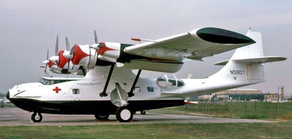
During the late 1960s Forrest Bird designed, and his Bird Corporation developed a conversion for the PBY Catalina to improve performance.
The Catalina was modified by adding two 340 hp (254 kW) Lycoming GSO-480-B2D6 engines positioned outboard of the original Pratt & Whitney radials to increase range and performance. (These engines and cowlings had originally been installed on the McKinnon four engine Grumman Goose. When they were removed by McKinnon to convert the Goose to twin turboprop power, they were purchased by Bird for his PBY Innovator conversion. Engineering for the Innovator conversion was performed by Spectro engineering of Los Angeles).
The wing attach fittings were strengthened and fuel capacity increased by adding fuel bladders to the outer wing panels. The engineer’s controls were previously moved to the cockpit by Southern California Air Service during their “Landseaair” conversion to allow operation without a Flight Engineer. Propeller control for the two Lycomings was electrical. The Lycoming’s propellers were fully reversible, distinctly improving the handling dexterity on the water. The main engine propellers were controlled by the standard mechanical linkage. The larger “Super Cat” rudder and increased power main engines (1830–94) had been installed at an earlier time. The angle of incidence of the wing and horizontal surfaces were not modified during the conversion.
First flying in 1967, the effect of the extra engines exceeded expectations, such that it was capable of a cruising speed of 152 mph (244 km/h) on four engines, and of maintaining 124 mph with one of the main engines feathered. The original PBY cruised at about 125 mph. The downside of the Innovator conversion was the gross weight of the aircraft increased to over 29,000 lbs. This exceeded the 27,000 lbs maximum that the US Military considered safe for water operations.
Only one Innovator was converted, a 28-5AMC Canso A (This was a Consolidated built aircraft. Built in November 1941 (under a contract for Canada), registration N5907, formerly RCAF serial number 9746, which was already used by Dr. Bird as a flying classroom/salesroom for medical equipment. Bird Corporation registered it as N81RD, and sold it in 1976, when its registration reverted to N5907. In the late 1970s, Pyramid Corporation purchased the Innovator and converted it to a camera platform to count whales along the west coast of the Americas. A plastic bubble with camera was installed in the nose and cameras were installed in the right blister and air stair door.
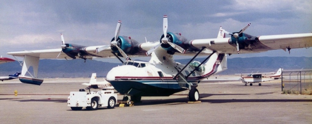
The Innovator was stored in Titusville, Florida at the end of this contract. While in storage a local law enforcement official decided that, since it was a large seaplane, it must have been used for illegal purposes and the aircraft was confiscated. Many years of lawsuits later, the Innovator was exonerated but time and the Florida sun had taken its toll. In the early 1990s, a New Mexico aircraft salesmen bought the Innovator, registered it as N5PY and spent the better part of a year restoring the aircraft to flying status. In 1997, during inspection, the new owners found an improper repair to the main keel truss from an earlier gear-up landing in the 1960s.
The extent of the damage, the previous attempt at repair and corrosion issues showed the need for a major IRAN (Inspect and repair as necessary) of the aircraft. At this time it was decided that, due to the extreme weight gain and aging complexity of the Innovator conversion, returning the aircraft to its original twin engine “Landseaire” condition was the safest and best option for the future preservation of the aircraft. As of 2013, restoration continues with the bow, pylon, and tail sections completely restored and a complete new keel truss, keelson, stringers, and bottom skins currently being installed; currently registered as N5PY.
Innovator
Engines: 2 × Pratt & Whitney R-1830-94 Twin Wasp, 1,350 hp (1,010 kW) with 3-bladed Hamilton Standard constant-speed propellers & 2 × Lycoming GSO-480-B2D6, 340 hp (250 kW) with 3-bladed Hartzell 83XF-3A fully-feathering reversible-pitch propellers
Wingspan: 104 ft 0 in (31.7 m)
Wing area: 1,400 sq ft (130 m2)
Aspect ratio: 7.73
Length: 63 ft 10 in (19.46 m)
Height: 20 ft 2 in (6.15 m)
Gross weight: 29,000 lb (13,154 kg) +
Fuel capacity: 1,750 US gal (1,457 imp gal; 6,624 l) main tank + 375 US gal (312 imp gal; 1,420 l) in 3x additional bladder wing tanks
Cruise speed: 174 kn (200 mph, 322 km/h) maximum
137 kn (158 mph; 254 km/h) at 34,000 lb (15,422 kg) gross weight and 5,000 ft (1,524 m)
132 kn (152 mph; 244 km/h) at 64% power and 11,000 ft (3,353 m)
125 kn (144 mph; 232 km/h) starboard auxiliary engine feathered
124 kn (143 mph; 230 km/h) port auxiliary engine feathered
112 kn (129 mph; 207 km/h) both auxiliary engines feathered
110 kn (127 mph; 204 km/h) starboard main engine feathered
108 kn (124 mph; 200 km/h) port main engine feathered
Service ceiling: 15,000 ft (4,600 m) one main engine inoperative
Service ceiling: 10,000 ft (3,048 m) with both port engines inoperative
Rate of climb: 750 ft/min (3.8 m/s) at 75% power at sea level
Take-off run: 1,000 ft (305 m) at 34,000 lb (15,422 kg)
Take-off at 85% power: < 2,000 ft (610 m) at 34,000 lb (15,422 kg)
Crew: 2
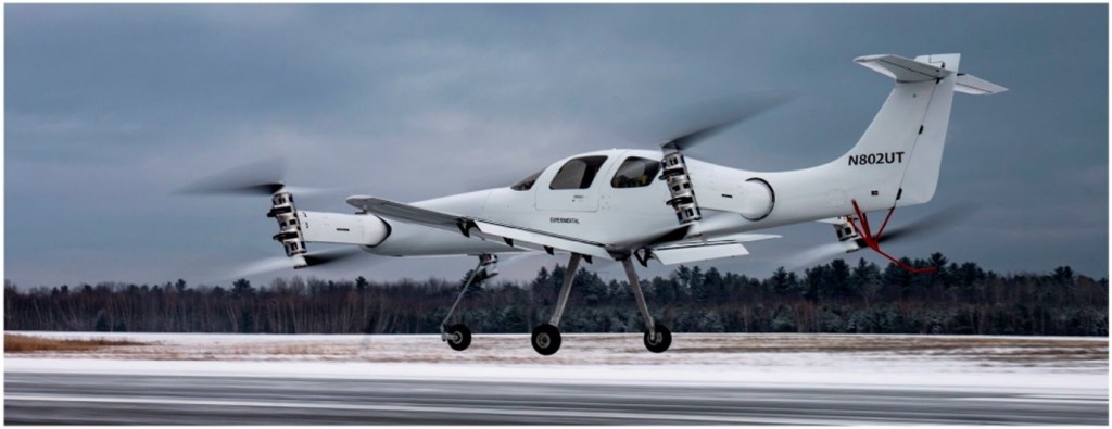
Beta Technologies flew their Ava XC technology demonstrator on 22 June 2018 with four contrarotating, tilting rotors mounted on the wing tips of a vehicle that resembles a fixed wing aircraft. As with demonstrators developed by other manufacturers, the Ava XC was developed to gain familiarity with eVTOL technology.
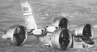
The X-22A was designed for evaluation of the tilting-duct concept in an airframe that might form the basis of a light V/STOL transport. It was also designed to provide a versatile platform capable of general research on V/STOL handling qualities using a variable stability control system.
The Tri-Service V/STOL Transport Program addressed needs of the Army, Navy, and Air Force, to develop a small number of prototype V/STOL transport aircraft that used different concepts and to perform operational evaluations of their usefulness.
The Navy studies showed that a duel tandem ducted fan configuration permitted a shorter wing span for a given weight, allowing a stubbier design that could fit on existing carrier elevators and would eliminate the need for complex wing folding mechanisms. The duct around each of the four props also would improve propeller efficiency and provide a safety benefit to personnel working on a ship’s flight deck.
The Navy awarded a $27.5 million contract for the design and development of two identical X-22s to Bell Helicopter of Niagara Falls, NY, in November 1962. Bell’s internal designation was the Model D2127. Bell had already Bell built and flew the Air Test Vehicle and X-14 VTOL research aircraft. Representative of a possible small V/STOL transport, the X-22 could carry a 540kg payload and could carry up to six passengers. Its length and wingspan were each a little over 11.9m, and maximum gross weight was 7530kg.
The rectangular fuselage accommodated at its rear a wide-chord wing fitted on its leading edges with two groups of two 1250-shp (932-kW) General Electric YT58-GE-8B/D turboshafts to drive four propellers (or fans) located inside annular ducts. These last were located at the tips of the wings and the short span foreplane and could be turned between the vertical (for vertical take-off and landing) and the horizontal (for forward flight). Change in the propeller pitch produced the thrust modulation for control, and was supplemented by movement of aileron in the slipstream of each duct. The “B” and “D” designations on the engines referred to two engine configurations that differed only by their fuel controllers. They powered a common drive shaft that turned all four props. These engines had both controllers and switched between them automatically based on whether the X-22 was operating in hover mode or cruise mode. 465 gallons of useable fuel was carried in fuselage tanks.
The power transmission system consisted of a total of ten gearboxes. It reduced the engine’s nominal 19,500 revolutions per minute speed down to the propellers’ nominal 2,600 revolutions per minute. This arrangement also allowed all four props to continue operating with any number of engines failed or intentionally shut down.
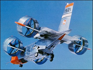
The four Hamilton Standard propellers, 2.1m diameter, 3-bladed props were fabricated of fiberglass bonded to a steel core, making them 25 percent lighter than metal props yet giving them three times the fatigue strength. A nickel sheath was mounted over the leading edge. Very high prop efficiency was achieved by placing the props inside of the ducts, so much so that the X-22 could still take off on three engines, fly on two, and make a conventional landing with only one. The two forward ducts were mounted to small pylons on the forward fuselage, and the two rear ducts were mounted to stubby, dihedralless wings on the aft fuselage. Hydraulic actuators rotated each of the four ducts, but mechanical and electrical interconnections insured that all rotated together.
Thrust control could be obtained by varying the blade angle. Four elevens, one placed at the rear of each ducted fan assembly, were the only control surfaces. Placing the elevons in the prop slipstream made them very effective, even at low airspeeds. Despite the significant looking vertical stabilizer, there was no rudder. Movement of the elevons and changes to the prop pitch achieved all flight control.
Flight control in horizontal flight was achieved using a conventional looking control stick for pitch and roll. Moving the stick caused the elevons to move, either differentially between the front and rear for pitch, or differentially on left and right sides for roll. Yaw was achieved by moving the rudder pedals, which changed the propeller blade angles to produce differential thrust. There were also throttles for each engine and a lever to control the angle of the ducts. In forward flight, the front ducts were rotated to 3 degrees up from horizontal and the rear ducts rotated to 2 degrees below horizontal. This gave an optimum incidence of 5 degrees between the two pairs.
The cockpit arrangement included two zero-zero ejection seats set side-by-side, full conventional instrument displays (plus a master tachometer for propeller revolutions and a duct angle indicator) duplicated for each pilot. Engine controls were gathered on the central console.
While hovering, the pilot used the same control stick to control pitch and bank motions. Stick inputs caused the flight control computer to command minute changes to the prop blade angles to vary the thrust, causing the X-22 to tip forward, aft, or sideways. Yaw was controlled by moving the rudder pedals, by differential movements of the elevons between the left and right sides. The pilot also could rotate the ducts to assist the fore/aft motion during hover.
During transition, with the ducts at some intermediate angle, the pilot’s control inputs produced mixed propeller pitch and elevon deflections. The ratio of mixing between the props and elevons was a function of the duct angle. The ducts rotated at 5 degrees per second.
The X-22’s flight controls also included a variable stability system. This was another flight control computer that modified the basic airplane responses so that the characteristics of other aircraft, either real or imagined, could be produced. The variable stability system followed algorithms that were developed specially for each test and programmed into the computer. They produced extra control surface motions that caused the X-22’s flight characteristics to be varied, thus producing motions that are not characteristic to the X-22 airframe, but rather to the aircraft being simulated. This gave the X-22 the capability to perform research that would be applicable to a broad range of other aircraft, not just the unique characteristics of the X-22 itself. The Cornell Aeronautical Laboratory designed the variable stability system.
The first X-22, US Navy Bureau Number 151520, rolled out on May 25, 1965, and was followed by fifty hours of propulsion tests in a test stand. The flight test program was undertaken by Calspan Corporation, in Buffalo, New York, under the auspices of the U.S. Navy. The first flight in hovering mode was not made until March 17, 1966. On this 10-minute flight, four vertical take-offs and landings and a 180 degree turn were made. It then performed a series of STOL take-off and landing tests with the ducts tilted at 30 degrees. The first X-22 was damaged beyond repair on its fifteenth flight on August 8, 1966. It had flown only 3.2 hours, but suffered a dual hydraulic failure about four miles from its base at Niagara Falls Airport. The first transition from wing-borne flight to vertical flight was made under the stress of an emergency landing. The fuselage broke in half, with the rear section coming to rest inverted. While the aircraft was lost, neither pilot was injured. Swivel fittings were used in the ducts to provide hydraulic fluid to the elevon actuators. Both failed due to excess vibration. The fix included replacing the swivel fittings with loops of flexible tubing, replacing the aluminum hydraulic lines with ones made of stainless steel, and placing additional clamps on the hydraulic lines to minimize vibration.
The first was damaged beyond economical repair and it was cannibalized to keep the second aircraft flying, although the fuselage was retained for use as a ground simulator at Calspan.
The second X-22, BuNo 151521, rolled out took place on 30 October, 1965 and flew on 26 January, 1967, with Stanley Kakol and Richard Carlin in the cockpit, for a first 10-minute hover flight. Bell test pilots Stanley Kakol and Paul Miller were at the controls. The first transition being successfully made on 3 March.
With pilots from Bell, the Army, Navy, and Air Force, the X-22 flew frequently over the next several years. At the completion of the Tri-Service testing in January of 1971, the X-22s completed 228 flights, 125 flight hours, performed over 400 vertical take-offs and landings, over 200 short take-offs and landings, and made over 250 transitions. It also hovered at 2440m of altitude and achieved forward speeds of 507km/h. These flights demonstrated that the X-22 had good basic stability and that vertical take-offs and landings could be performed easily. Operation in ground effect was a little less stable, but still positive. Hovering was easier than in most helicopters. In horizontal flight, all responses to pilot control inputs were excellent. Transitions were accomplished with minimum pilot workload. Landing position could be controlled precisely. The aircraft was still controllable without augmentation, but required a significant increase in pilot workload. This system provided rate damping in pitch, roll, and yaw only during hover and low speed flight.
With the Navy satisfied with the basic operation, they awarded a contract to Cornell in July 1970 to operate and perform flight research using the X-22, with particular emphasis on operating in the variable stability mode.
Over the next ten years, Calspan flew five test programs:
Numerous problems were discovered and fixed during testing. While all were fixed, they were not necessarily fixed in an optimum manner, as would be done for a production aircraft. Further development may have provided an optimal solution. But, being a research aircraft, a fix that worked for the intended mission was good enough. Some of them included the following:
For two full years, the X-22A was involved in a flight-test programme with Bell and the NASA. During this period some 220 flights and 110 flying hours were logged. This phase was followed, in January 1968, by a first military preliminary evaluation during which the X-22A was examined by pilots and engineers of the three Services and accomplished fourteen flights. A second military evaluation took place at the beginning of the following April. During this period, the X-22A demonstrated. good performance such as a sustained hover at an altitude of 2400m. On 19 May, 1968, the X-22A was officially taken on charge by the US Navy which turned it over almost immediately to Calspan Corp responsible for the test programme on behalf of the Navy. The prototype had been equipped with an automatic flight control system known as LORAS (Linear Omnidirectional Resolving Airspeed System). This programme, which was broken down into several tasks, totalled 273 flights, 279.9 flying hours, 130 VTOL take-offs and 236 VTOL landings. The aircraft was flown until the autumn of 1984 when flight testing was considered terminated. The X-22A made its last flight in 1988.
Engines: 4 x General Electric YT58-GE-8B/D turboshaft, 932kW / 1250hp
Wingspan: 11.96m / 39 ft 3 in
Length: 12.06m / 39 ft 7 in
Height: 6.3m
Take-off weight: 8172kg
Empty weight: 4302kg
Max speed: 370 km/h
Cruising speed: 343km/h
Range: 716km
Ceiling: 15,000 ft.
Fastest Flight: 255 mph
Total Flights: 500+
Highest Flight: 27,800 feet (approx)
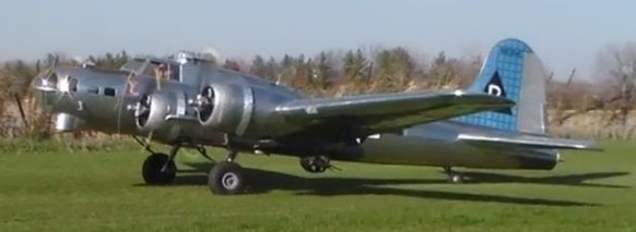
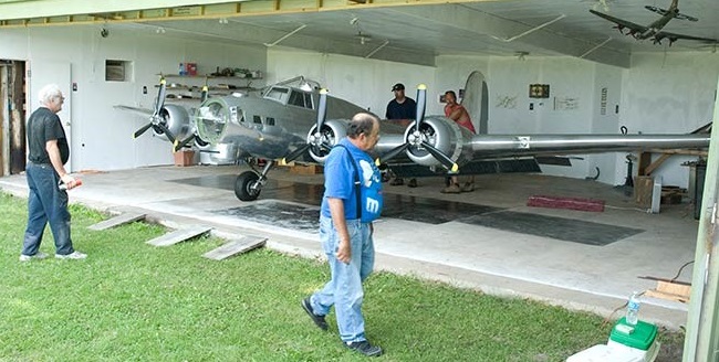
Bally’s Bomber is a ⅓ Scale B-17G aircraft built using 1/9 scale RC model aircraft plans, and carries a single pilot. It is powered by four Hirth 3002 4-cylinder 2-stroke engines, spans 34′ 7″ and weighs an estimated 1,800 lbs.
The unique aircraft received airworthiness certification in September 2016 following initial engine and taxi tests. The first flight was intended to be a high speed taxi test, but the machine was said to “just kind of [take] off”.
On 14 November 2016 Jack Bally`s 1/3 scale B-17 replica performed its maiden flight, departing from its home field in Illinois for a short flight to a local airport, where it was to undergo continued flight tests.
Power Plant: 4 x Hirth 3002, 60 hp
Wing Span: 34 ft. 7 in.
Length: 25 ft.
Tail Height: 6 ft. 10 in.
Fuel Capacity: 42 USgal.
Empty Weight: 1800 lbs. (Est.)
Cruising Speed: 110 kts. (Est.)
Crew: 1
Number Built: 1
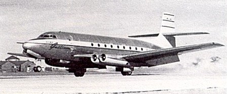
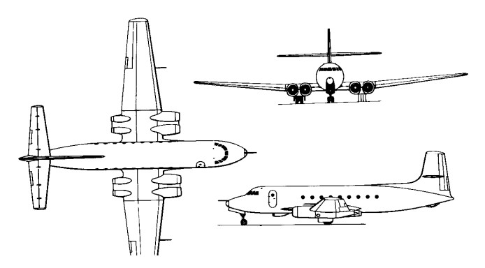
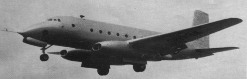
The design for a 50-seat medium-range civil transport began in 1946 initially proposed with two Rolls-Royce Avon turbojets but by autumn 1947 it was apparent these were not available. The design was modified to take four 3600 Rolls-Royce Derwent 5s.
With tricycle landing gear, and four turbojets, the prototype was first flown on 10 August 1949, but only six days later was badly damaged through a landing gear failure. It was repaired and flying again within a few weeks, and its four Derwent 5 engines were replaced by two Derwent 8s (starboard outer, port inner) and two Derwent 9s for evaluation. Construction of a second C-102 prototype began, but was not completed.
The C-102 integral fuel tanks have 1375 Imp.Gal inboard and 1025 Imp.Gal outboard giving a total capacity of 2400 Imp.Gal.
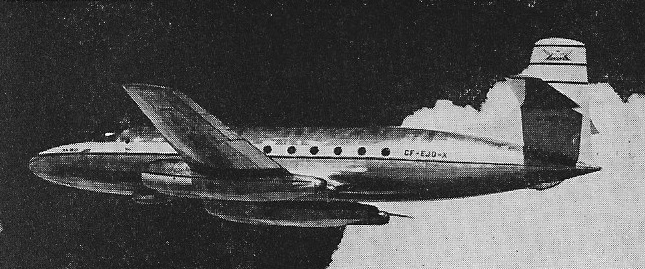
Despite an aggressive marketing campaign directed at U.S. airlines and the USAF, the sales prospects of the Jetliner floundered after the launch customer, Trans-Canada Airlines, reneged on a letter of intent in 1948. The company was still attempting to get the CF-100 into production at the time and, consequently, the Canadian government cancelled any further work on the C102 due to Korean War priorities: C. D. Howe demanded the project be stopped to increase production of the CF-100, so the second C102 prototype was scrapped in the plant in 1951, with the first relegated to photographic duties in the Flight Test Department. After a lengthy career as a camera platform and company “hack,” CF-EJD-X was flown for the last time on 23 November 1956 and broken up in 1956, having flown about 425 hours. The nose section now resides in the Canada Aviation Museum in Ottawa.
C-102
Engines: 4 x Rolls-Royce Derwent 5, 1633kg / 3600 lb
Wingspan: 29.90 m / 98 ft 1 in
Wing area: 107.49 sq.m / 1157.01 sq ft
Length: 25.12 m / 82 ft 5 in
Height: 8.06 m / 26 ft 5 in
Take-off weight: 29480 kg / 64993 lb
Empty weight: 16740 kg / 36906 lb
Max. speed: 735 km/h / 457 mph
Cruise speed: 650 km/h / 404 mph
ROC: 1595 fpm
Ceiling: 12285 m / 40300 ft
Range: 2000 km / 1243 miles
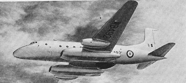
Originally titled Tudor 8, modifications to the Tudor airframe needed to produce the test beds were considerable enough to warrant a new name.
The Tudor 8 was first flown on 6 September 1948 when it flew from Woodford to Boscombe Down. The Tudor 8 was demonstrated at Farnborough on 7 September 1948 with four Roll-Royce Nenes of 5000 lb thrust.
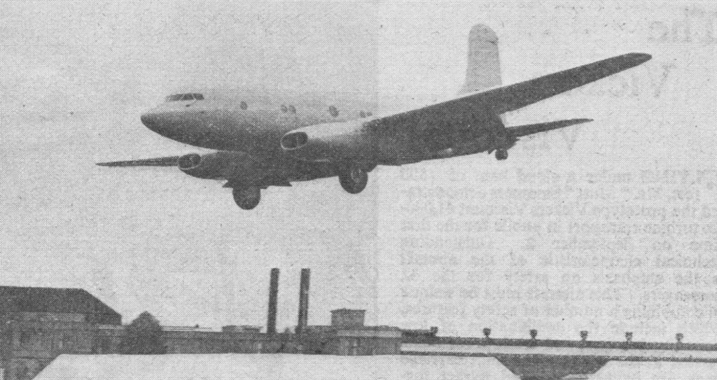
Six Ashtons on order in 1950, which were built for the Ministry of Supply to act as test-beds for research into jet operations.
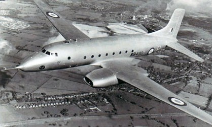
The first Ashton made its maiden flight on 1 September 1950.
Powered by four 2270kg Rolls-Royce Nene 5 and 6 engines, the Ashton featured a nosewheel undercarriage which retracted forwards.
Four marks of Ashton were built.
Mk.1
High altitude turbojet research
Engines: 4 x Rolls-Royce Nene 5 and 6, 5000 lb
Wingspan: 120 ft
Length: 89 ft 6.5 in
Height: 31 ft 3 in
Loaded weight: 72,000 lb
Max speed: 439 mph
Cruise: 406 mph
Mk.2
High altitude air conditioning tests
Mk.3
Ventral radome and bomb containers outboard of engine nacelles
Bomb sight development
One Mk.3 used as Bristol Olympus testbed
Mk.4
Instrument development
Engines: 4 x 2270kg Rolls-Royce Nene 5 and 6
Take-off weight: 32688 kg / 72065 lb
Wingspan: 36.58 m / 120 ft 0 in
Length: 27.28 m / 90 ft 6 in
Height: 9.53 m / 31 ft 3 in
Wing area: 132.02 sq.m / 1421.05 sq ft
Max. speed: 707 km/h / 439 mph
Cruise speed: 654 km/h / 406 mph

