Grokhovsky G-52

In 1934 Grojovski began experiments installing conventional weapons used by ground units on bombers. Initially as part of the experiments, he fitted a Tupolev TB-3 bomber with a 76mm regimental gun. The gun was installed under the fuselage, in a structure 600 mm from the bottom of the fuselage. The tests were carried out between December 15 and 18, 1934, first with shots from the ground and then during the flight. As a result of these tests, it was declared that firing with 76mm regimental guns from aircraft is possible.

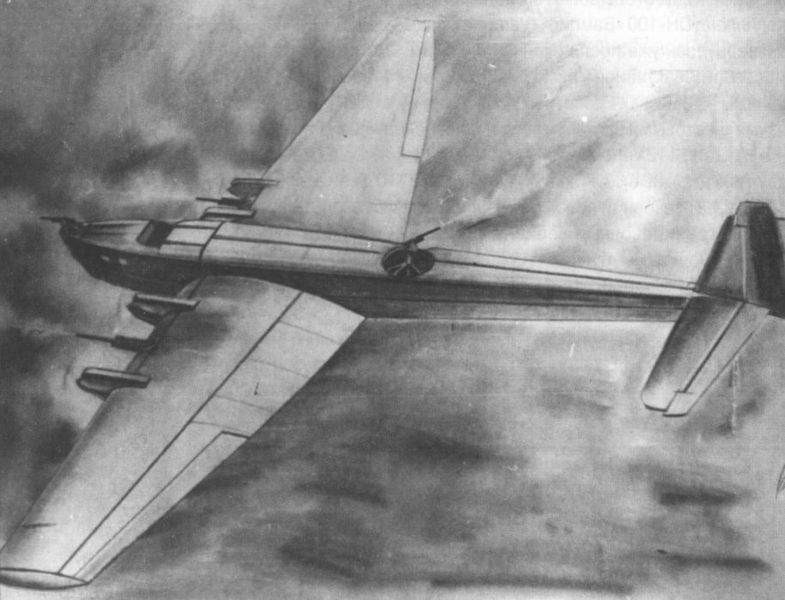
After these results Grojovski began the development of a version with more powerful weapons, again on a TB-3 bomber. This version was called “Letayuchaya Baterieya” or “Flying Drums” and received the designation G-52 (Russian: Гроховский Г-52 “Летающая Батарея”) in the institute’s consecutive year.

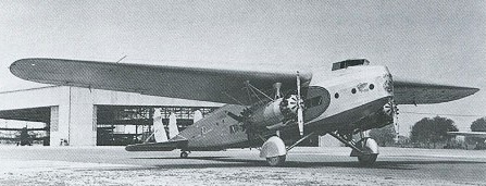
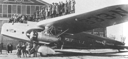
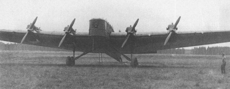
The G-52 “Letayuchaya Baterieya” heavy attack aircraft was submitted for state tests in December 1935. It was a Tupolev TB-3 bomber with M-17 engines and armed with cannons.

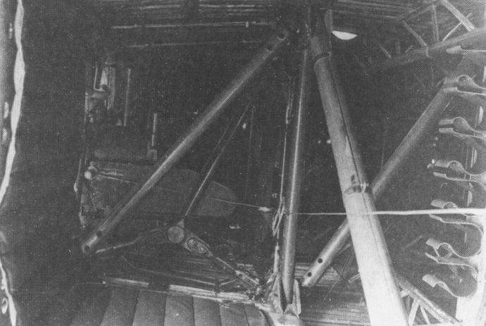
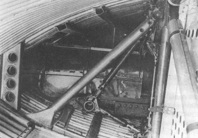
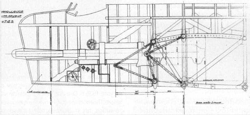
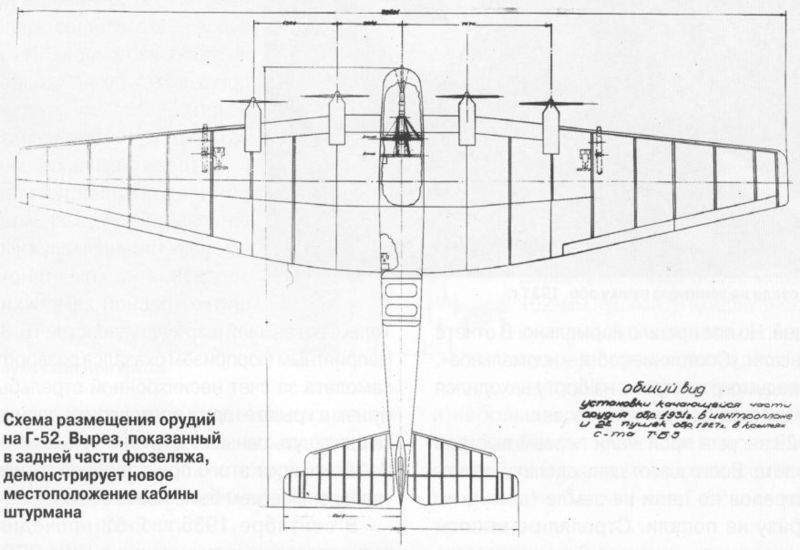
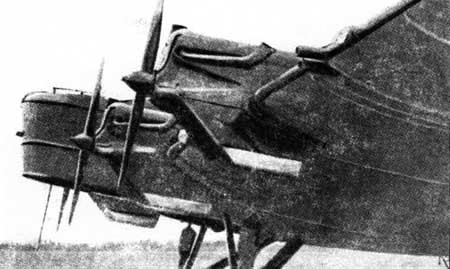
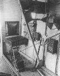
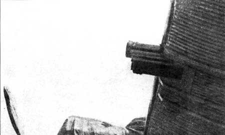
After reviewing several installation variants, it was agreed to install a 76 mm anti-aircraft gun (1931 model in the nose.). The developers were forced to shorten the nose, which forced the elimination of the navigator’s position in the bow. The long tube of the gun was located between the pilots’ stations, protruding by about 250 mm at the bow of the aircraft. The body of the cannon was fixed to the upper and lower partitions of the spars of the center plane, by means of a system of adjustable rods. From the nose and up to the pilots’ position, the barrel was covered with a tube to prevent the entry of gunpowder gases into the cockpit. The reloading of this cannon for firing was done manually. To achieve this, the gun server position was located in the fuselage, with a small seat and some shelves for the projectiles.

In the wing consoles two 76 mm field guns (1927 model). To install the guns on the TB-3 bomber , the gun carriage with the wheels was eliminated, maintaining the recoil compensation system. The server for each gun sat during the flight on a mattress attached to the wing structure.

Grojovski G-52 during state tests

The main task for which the G-52 was conceived was fire support to landing troops. The range of the artillery salvoes was 18 km and the location of the target was done during the turn. To achieve some aim, a standard collimator was located in front of the ship’s commander’s post. Each shell had a weight of 6.5 kg.

According to the assertions of its builders, the three cannons of the “Letayuchaya Baterieya” could fire up to 27 shots per minute. This really does not seem credible due to the lack of automatic recharging systems at the time.

The order to fire was obtained by means of light indicators. The ship’s commander had a control board with switches and indicator lamps. 

When the commander connected the switch, the piece received the instruction to prepare to fire. When loading the projectile, the server of the piece pressed his switch to indicate that he was ready. After taking the plane to the target, the commander pressed a button and a red light illuminated in the room, indicating the order to fire. In case of need, the wing guns could be fired using a remote control system. For this purpose, cables were located from the cockpit to the wing locations.

The navigator, originally located in the bow of the bomber, in this version came to occupy a position on the left side of the rear part of the fuselage, just above the wing trailing edge area.

This system in general must have turned out to be not very functional, first of all due to the need to approach the target without an aid system for the pilots, maintaining the course during the entire approach despite the interference caused by the enemy fighters and the anti-aircraft systems. On the other hand, the lack of aiming systems guaranteed a very low level of success. During the tests it was also found that the smoke from the cannon shot leaves the pilots practically without visibility.

Grojovski’s experiments in this direction were simply abandoned.

Goodyear RS-1

The first semi-rigid airship designed and built in the United States, the RS-1 project was initiated in 1922 and became a joint effort of the Air Service and the Goodyear Tire and Rubber Company of Akron. Ohio. It was designed by Goodyear engineer and inventor, Herman Theodore Kraft. A contract was signed with Goodyear on 13 October 1922 and actual construction was started at the Goodyear facility in Ohio in 1923.

The ship used helium as a lifting medium and power was by four 300 hp Liberty 12 engine. There were two power cars, each having a pair of engines driving a single 17 ft 6 in propeller through a transmission designed and built specifically for the RS-1. The contract to build the transmission was given to Goodyear along with one to built the airship itself. Goodyear subcontracted the transmission to the Twin Disc Clutch Co of Racine, Wisconsin. The design work was done by Thomas Farwick. Three units were built, one for testing and use for any refinements required, and two for installation in the RS-1. The first unit was delivered to McCook Field and passed is 50 hr test in the Summer of 1925. The remaining two units were delivered directly to Goodyear.

The design provided 12 to 5 reduction gearing to a single 17 ft 6 in propeller being driven by either two 300 hp Liberties or by a single one. The transmission could reverse the direction of the propeller but one engine had to be disengaged during the operation. Either or both engines could be disengaged by its own disk clutch.

The engines were mounted in staggered form. Each had its own disengaging clutch. One drove a transmission input through a short shaft and the ther through one long enough to clear its adjacent engine.

The ship was delivered to Scott Field in early 1925 where it was erected. A 35 ft (10.7 m) enclosed control car is suspended from the keel at the nose. Equipment included a bombing cockpit and the ability to carry 3,500 lb (1,588 kg) of bombs, as well as mounts for machine guns on each side at the forward end of the car.

Along the belly of the envelope is an enclosed aluminium alloy keel, suspended by catenary cables, which attach to the three points of the keel at 10-ft. intervals. The load coming on the centre catenary gives the envelope a heartshape transverse cross-section, of which the greatest dimensions are 66.5 ft by 73 ft high. The envelope is divided into four compartments by transverse diaphragms. The centre diaphragm is a solid wall, while the end ones have surge holes near the bottom in the gas and air compartments.

It was inflated and subjected to numerous tests and was taken on its maiden flight. The first flight was delayed due to a mistake made by a rigger during erection and eventually took place on 8 January 1926, lasting just over an hour with a crew of eight men.

On its initial trial flight, on January 8, it made a successful trip of over an hour’s duration in a mild snowstorm, carrying a crew of eight men and with Lieut. Orval Anderson in charge. During a subsequent test flight the RS-1 encountered extremely bumpy flying conditions and winds that at times exceeded 50 mph. After a flight of 19 hours’ duration, however, the RS-1 was landed at its home base in a high ground wind without mishap, the personnel rendering a favourable report of the ship’s entire performance.

13 May 1926

In 1927 the Liberty engines were replaced by 2A-1500 Packard engines. The Packards were lighter by about 150 lbs. The normal rating of the Packards was 500 hp at 2000 rpm and 600 hp at 2500 rpm. The props were replaced with 16 ft diameter.

Four airships on the ground (USS Akron, USS Los Angeles, Goodyear RS-1, Pony Blimp)

The airship was taken out of service in November 1928 because of envelope porosity pending its replacement, but because of economic conditions, a new envelope was never installed and the airship was eventually scrapped.

Engines: 4 x Liberty 12, 300 hp / 220 kW
Capacity: 719,500 cu.ft / 20,000 m3
Length: 282 ft / 85.95 m
Diameter: 70 ft 6 in / 21.49 m
Width: 74 ft 6 in
Height: 66 ft
Max speed: 75 mph+ / 121 km/h / 65 kn
Cruise speed: 45 mph / 72 km/h / 39 kn
Useful load: 12,138 lb

Gloster TC.33

The appearance in 1930 of the four-engined troop carrier (TC) TC.33 was a complete break from their tradition and was the only four-engined aircraft that Gloster ever built. It was designed led by Henry Folland to meet Air Ministry specification C.16/28, which required the ability to carry 30 troops and their equipment for 1,200 miles (1,930 km) and was the same specification that produced the Handley Page H.P.43 and the Vickers Type 163.

The TC.33 was a large single bay all-metal biplane with no stagger and 7° sweepback. Both wings had metal lattice spars and metal ribs with fabric covering. The lower wing was unusual in that its centre section had marked anhedral so that the main spars met at the top of the fuselage, leaving the interior unobstructed. The outer end of this centre section was strut braced to the lower fuselage. The TC.33 also had a lower wing of (slightly) greater span than the upper.

The four evaporatively cooled Rolls-Royce Kestrel engines were mounted in two nacelles, each containing a tractor-pusher pair together with their steam condenser and mounted between the wings at the end of the centre section. They were each carried by two vertical struts above the nacelle, complicated strutting below and by further strutting to the lower wing roots. The wide (22 ft 6 in (6.8 m)) split axle undercarriage had vertical legs from the front wing spar at the same point and bracing from the axles to the fuselage.

The fuselage was oval in cross section and smoothly metal skinned. The cockpit was enclosed, but there were open gunners’ positions at nose and tail. Like the cockpit, the long main cabin was heated and soundproofed. There was a large hatch in the floor for heavy loads with an integral hoist mounted above it, plus a smaller roof hatch through which loads could be lowered by crane. The biplane tail unit had conventional fabric covered endplate fins and rudders, but the tailplanes were sesquiplane type. The upper tailplane and elevator was strut mounted above the fuselage and the much narrower chord lower part fixed to the lower fuselage.

The prototype was completed in January 1931 and, because the hangar doors were low, the undercarriage had to be assembled in two trenches. The aircraft was winched in and out of the hangar by way of these trenches.

The TC.33 first flew on 23 February 1932. Development flying showed it had good performance but suffered from elevator and rudder flutter. The former was cured with mass balancing but the rudder flutter persisted, particularly in high speed dives until the rudders were redesigned.

It was exhibited at the 1932 RAF Hendon Display and then went on to RAF Martlesham Heath for trials. Once in the air, the TC.33 was judged a pleasant machine to fly, but it was crucially let down by its full load take off performance. Even at Martlesham it was hard to get it off the ground in a reasonable distance. The undercarriage behaviour was also criticised. Because of these concerns over take off performance at English temperatures and altitudes, the Air Ministry did not place an order, judging it would not cope with the hot and high conditions found at many RAF fields across the Empire. Thus J9832 was the only one of its kind. None of the C.16/28 contenders were awarded a production contract.

Gallery

Engines: 2 × Rolls-Royce Kestrel IIIS, 580 hp (432 kW) & 2 × Rolls-Royce Kestrel IIS, 580 hp (432 kW)
Props: 12 ft 6 in (3.8 m) diameter two bladed fixed pitch tractor & 11 ft 0 in (3.3 m) diameter two blade fixed pitch pusher
Length: 80 ft 0 in (24.38 m)
Wingspan: 95 ft 1 in (28.98 m)
Height: 25 ft 8 in (7.82 m)
Wing area: 2,493 ft2 (231.60 m2)
Empty weight: 18,399 lb (8,346 kg)
Gross weight: 28,884 lb (13,101 kg)
Maximum speed: at 13000 ft (3,960 m) 142 mph (227 km/h)
Service ceiling: 19,100 ft (5,821 m)
Rate of climb: to 10,000 ft (3,050 m) 408 ft/min (2.1 m/s)
Armament: 2 × 0.303 in (7.7 mm) Lewis gun, in front and rear positions & 3,600 lb / 1,633 kg bomb load on racks below fuselage
Crew: 4
Capacity: 30 troops

General Aircraft GAL.38

In 1937 the British Admiralty issued a requirement for a novel type of aircraft to shadow enemy fleets, especially by night. The Air Ministry issued Specification S.22/37 calling for an aircraft compatible with aircraft carriers which would provide comfortable accommodation for a pilot, observer and radio operator, outstanding all round view and the ability to cruise at 40 knots for 11 hours. Two prototypes were built, the Airspeed A.S.39 (serial N1323) and the General Aircraft G.A.L.38 (P1758). These flew after the out break of the Second World War. Both were high wing aircraft with extensive slats, flaps and drooping ailerons all in the slipstream of four 130 hp Pobjoy Niagara V radials driving fixed pitch propellers. The G.A. aircraft was all wood, but the Airspeed Fleet Shadower, had a metal fuselage; the former had a nose¬ wheel and tall single fin, while the Airspeed had a tail wheel and three small fins. Each seated the observer in a panoramic nose, the pilot high and behind and the radio operator further aft. Both aircraft met the requirement but the Admiralty changed their minds about the desirability of such an air¬ craft and scrapped this programme in 1940.

Span: 17.02m (55ft 10in)
Length: 11 m (36 ft 1 in)
Gross weight: 3897 kg (8590 lb)
Maximum speed: 185 km/h (115 mph).

Fouga CM.10 / CM.100 / CM.101R /  Castel-Mauboussin CM.10

CM.100

The Castel-Mauboussin CM.10 transport glider was built for French military forces, also the CM.100 powered version with two Renault engines. In the latter CM-101R Renault engines were augmented by two Turbomeca Pimene turbojets.

CM.10 — 1947 wooden assault glider, 35 troops, 26.96 m span, 2 prototypes
CM.10: Fouga-built glider prototypes evaluated by Armée de terre, 1947
Prod. order for 25 (SNCAN-built) cancelled after crash of CM.10 n° 1
CM.100: 1949 powered vers., 2 x Snecma 12S (As 411), 1 built (F-WFAV)
NB: study begun Nov 1944 for Armée but civil vers. envisioned by SGAC
CM.101R: F-WFAV with added wingtip-mounted Turboméca Piméné turbojets
CM.103R: [Project] military CM.101R variant, 2 x Turboméca Marbore turbojets

Forlanini F.3 / P Class

Manufactured by the Società Leonar¬do da Vinci in Milan, the ‘Forlanini’ class airships (designed by Enrico Forlanini and the firm’s engineer Luigi Crescentini) may be regarded as the most successful of the Italian semi¬rigid vessels, winning a number of re¬cords during the years immediately preceding World War 1. Early versions had carried their structural girder externally, but this was eventually placed within the hull as a truss from which the central car with its crew compartment, motors and flotation bags protruded, the leading edge being glazed and an unusual tri¬plane set of control surfaces being car¬ried at each side of the F.3. To the rear of the car the propellers, arranged as pushers, were carried on outriggers with an extended linkage to the en¬gines, the reversible propellers being capable of variable pitch.

An interesting design feature of the envelope was its double surface with a space between the inner and outer fabric, which served as a ballonet to maintain the shape of the envelope. In addition a climbing well was included together with a ladder by which to gain access to a platform on top of the hull.

There were five initial ‘Forlanini’ airships with progressively improved performance, the best showing a rate of climb of 1000 m (3,300 ft) per minute. One such airship setting up an endur¬ance record of eight hours, in the course of which the average altitude maintained was 3960 m (12,992 ft) although at one time 5335 m (17,503 ft) was attained.

Perhaps the most unusual feature of the Forlanini was the construction of the tail. This did not terminate in the conventional cruciform pattern but had instead a robust ventral fin of thick section. To each side of this and below the centreline a series of high aspect ratio rudders was carried (five to a side) with biplane horizontal surfaces above and below.

A Forlanini F.3 was built to a British Admiralty order in 1913, and to be known as Naval Airship No.11, but ws appropriated by the Italian Government at the outbreak of war in 1914. Two further airships of this design, No.12 and No.13, were to be built under licence by Armstrong Whitworth but were not proceeded with due to pressures of other war work.

A considerably smaller Forlanini airship was the ‘P’ class (Piccolo, or small) with a fixed vertical fin and out rigged rudders at the ends of very wide span elevators. This model was 63.0 m (206 ft 8.3 in) in length, with a diameter of 12.0 m (39 ft 4.4 in).

P Class
Propulsion: Four FIAT S.54-A, 80 hp
Volume: 13,790 cu.m
Maximum speed: 80 km/h
Flight endurance: 24 hr
Useful payload: 6 tonne

Forlanini F.3
Type: sea patrol and bombing airship
Powerplant: two 74. 6-kW (100-hp) Fiat A six-cylinder water-cooled piston
Maximum speed 80 kph (50 mph)
Service ceiling 5480 m (17979 ft)
Range 650 km (404 miles)
Useful lift 2720 kg (5997 lb)
Diameter 20.34 m (66 ft 8.8 in)
Length 95.1 m (296 ft 11.4 in)
Volume 13800 cu.m (487,343 cu ft)

Forlanini F.3
Engines: 2 x Isotta Fraschini V5 8-cyl, 180 hp
Envelope: 421,000 cu.ft
Length: 234 ft
Diameter: 58 ft
Height: 73 ft
Gross lift: 11.5 ton
Disposable load: 4.2 ton
Speed: 40 mph
Range: 600 miles
Crew: 10

Fokker F.XXXII / YC-20

The 32-seat F-32 was a Fokker Aircraft built in the US in 1934. No F-32’s ever landed in The Netherlands. It was a 4 engined aircraft, the engines mounted in tandem under the wing, 2 pusher engines and 2 tractor. Its four 525 h.p. Wasp engines were later replaced by 575 h.p. Hornets.

The F.XXXII was designed for Universal Air Lines, which had ordered five, but after an accident with the prototype, they cancelled their order.
The sleeping cabin of the largest Fokker craft ever built; the F.XXXII. As a night-liner it could accommodate 16 passengers, but in ¬normal configuration it seated 32. Hence the designation F.XXXII.
Five where built for Western Air Express where they flew for several years and the Army Airforce tested a cargo variant called YC 20. No orders where placed however. Fokker himself used a F-32 in the US as private aircraft.
Ten were built in total.

Engines: 4 Pratt & Whitney Hornet aircooled 9 cilinder engines/ 4 Pratt & Whitney Wasp engines
Wingspan: 30.18 m
Length: 21.28 m
Height: 5.03 m
weight: 10.985 kg
Cruise speed: 198 kph
Max speed: 250 kph
Ceiling: 4115 m
range 1191 km
Crew: 2/3
Passengers: 32