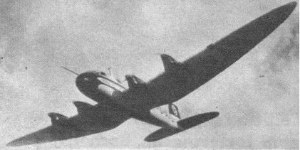
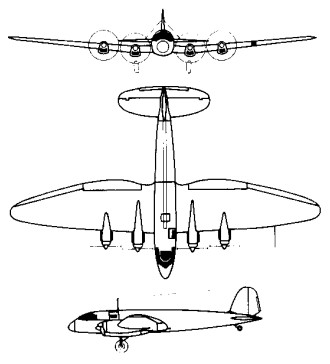
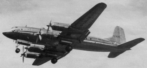
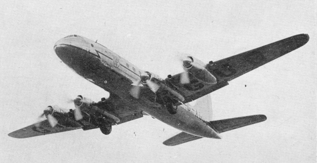
The He 116 was originally designed to fulfil a Deutsche Lufthansa requirement for a long range transport on its projected Far East mail route, fourteen aircraft of this type were built, five of them being military models. Building of the He 116 began in 1936. It had a metal fuselage and wooden framed large span wings, which accommodated four 270 hp Hirth HM 508C engines driving two-blade variable pitch propellers. The intention had been to use 500 hp Hirth engines, but these were not available in time. The first prototype, the He 116 V1, was completed in 1937, and an initial production series of eight machines was laid down. The first of these was the He 116 V2 (D AJIE “Schlesien”), all aircraft being allocated versuch or experimental numbers. The next four aircraft, also classed as prototypes were designated He 116A 0, the first making its maiden flight in the summer of 1937. Two of them were sold to the Japanese run Manchurian Air Lines with whom they remained in service until they were destroyed in late 1945. The two (J BAKD “Nogi” and J EAKF “Togo”) were purchased for use on mail services by Manchurian Air Lines. These reached Tokyo on April 29, 1938, having left Berlin six days earlier and completing the 9,532 miles (15 340 km) in a flying time of 54 hr 17 min, and subsequently served on the Tokyo Hsingking route. Another A series He 116 (D ARFD “Rostock”) was completed as a long distance record machine with 179kW / 240 hp Hirth HM 508H engines and an enlarged wing with a span and area of 82 ft (25 m) and 813.75 sq.ft (75.6 sq.m) respectively, and provision for rocket-assisted take-off equipment. Designated He 116R, on July 30, 1938, this aircraft established a new international record by flying 6,214 miles (10000 km) in 48 hr 18 min. During 1938 various powerplants and structural alterations were tried in two or three of the remaining aircraft in an attempt to fulfil the high speed potential of the design. One such experiment included the installation of four JATO rockets under the wings of the He 116R Rostock, formerly the A 03 or V3. Although the initial trial caused damage to the wings, another attempt was made on a closed circuit course and an inter¬national distance record of 10000 km (6214 miles) was achieved on July 30, 1938. The last two of the initial batch, the V7 and V8, were modified as prototypes for a military B series. Stripped of their civil fittings, and with a new glazed nose section, accommodation was available for two pilots, a radio operator and a navigator. Six He 116B 0 preproduction examples were ordered. Fitted with extensive photographic equipment, and joined by the similarly modified V7 and V8, they served within Germany with the Luftwaffe in the long range reconnaissance, aerial mapping and communications roles. They were unarmed, and were powered by 240 hp HM 508H engines. The R.L.M. began to evince interest in the aircraft as a long range photo reconnaissance aircraft and the ninth machine was built as the He 116B which was intended specifically for this role, and featured a completely redesigned and extensively glazed nose section. Five more He 116B aircraft (He 116 V10 V14) were built, and structurally these differed little from the commercial He 116A.
He 116A Engines: 4 x four 200kW / 270 hp Hirth HM 508C Max speed at sea level: 202 mph (325 kph) Max speed at 9,842 ft (3000 m): 233 mph (375 kph) Max speed at 16,400 ft (5000 m): 220mph (355 kph). Economical cruise at 9,842 ft (3000 m): 199 mph (320 kph) Economical cruise at 16,400 ft (5000 m): 186 mph (300 kph). Max range at 9,842 ft (3000 m): 2,237 mls (3 600 km) Max range at 16,400 ft (5000 m): 2,548 mls (4100 km). Climb to 3,280 ft (1 000 m): 4 min Climb to 6,562 ft (2 000 m): 8 min Climb to 13,120 ft (4000 m): 16.5 min. Service ceiling: 21,653 ft (6600 m). Empty wt: 8,929 lb (4 050 kg). Loaded wt: 15,719 lb (7130 kg). Wing span: 72 ft 2 in (22 m). Length: 44 ft 111/3 in (13.7 m). Height: 10 ft 10 in (3.3 m). Wing area: 677 sq.ft (62.9 sq.m). Crew: 3
He 116B 0 Span: 22m (72ft 2.25in) Length: 14.3 m (46ft 11 in) Gross weight: 7045 kg (15530 lb) Maximum speed: 325 km/h (202 mph).
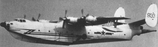
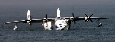
The SH-5 is an indigenous seaplane designed to replace the domestically produced Beriev Be-6s then in PLANAF service. Design work began in 1970, with the new aircraft aimed at performing maritime patrol and search and rescue duties. An entirely new in design, static testing didn’t begin until 1974. The Harbin Shuishang Hongzhaji 5 / PS-5 first flew April 1976, with series production commencing 1984 and 8-9 built to 1987 at Harbin.
The four-turboprop amphibian PS-5 appears to have the wing and powerplant of the Y-8 (An-12) transport and the tailplane and twin fins of the Beriev Be-6, combined with a new fuselage.
Powered by four 3,150 hp WJ¬-5A-1 (AI-24A) turboprops, PS-5S has 22,045-lb (10-tonne) max payload, includ¬ing four torpedoes or AShMs on underwing racks, or up to 13,227 lb (six tonnes) of depth bombs.
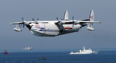
The SH-5 saw active use, and several of the aircraft were upgraded with EW systems. One example was converted for use as an aerial firefighter. In 2009, production of a new variant was announced with deliveries planned for 2014.
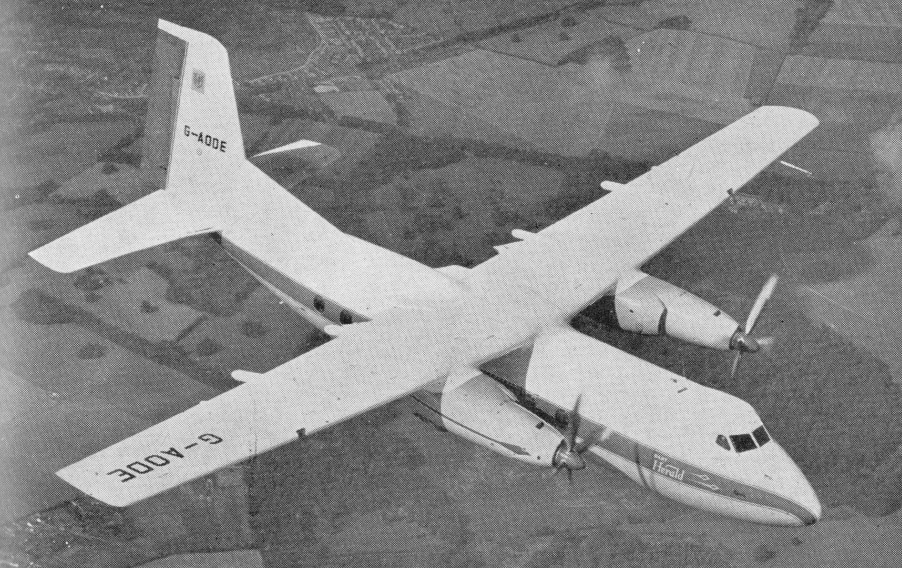
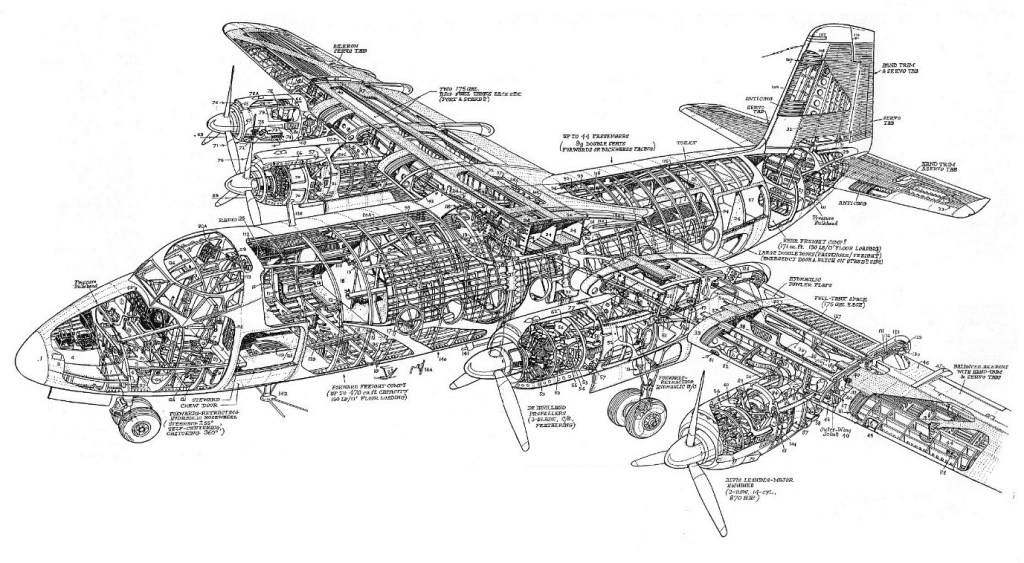
A medium sized transport designed to take the place of the DC 3, the Handley Page HPR 3 Herald design shows an essentially straight forward approach ¬with four piston engines, a high wing layout and a fuselage designed to carry 44 passengers, freight, or mixed loads. It is to be pressurized to a relatively low differential, and will carry a full payload of 10,705 lb. for a no reserve range of 350 st. miles, or 4,650 lb. for a full tank range of 2,050 miles.
The first Herald, G-AODE, flew on 25 August 1955 from Radlett, powered by four Alvis Leonides piston engines. Airborne for 30 minutes, the pilot was H.G.Hazelden. It appeared at that years SBAC Display.
Handley Page HPR.3 Herald
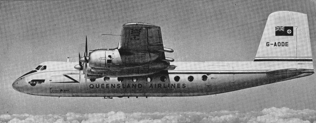
The first Handley Page Herald completed 125 hours flying in a year and received a Special Category of C of A in 1956.
By 1956 the Herald had been ordered by Queensland Airlines, Australian National Airways, Lloyd Aereo Colombiano and Air Kruise.
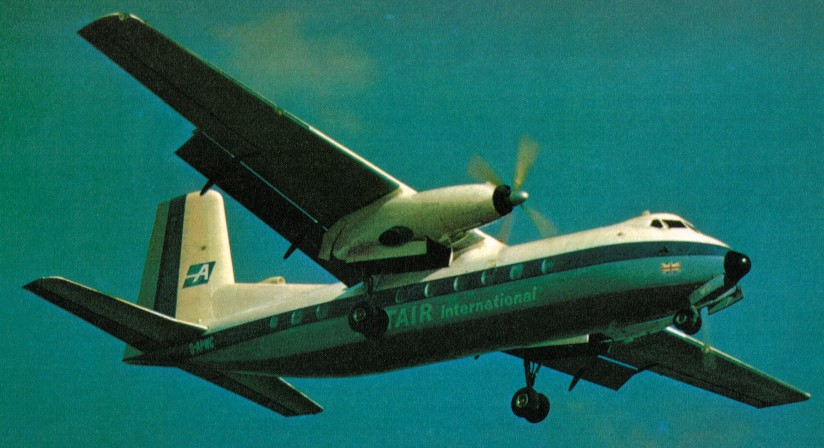
The prototype Dart-engined Herald made its first flight on 11 March 1958 and the first production Herald Series 100 flew on 30 October 1959. The Series 100 accommodated between 38 and 47 passengers. The Series 200 was the main production version with a forward fuselage 1.07m longer than that of the Series 100. Accommodation was provided for 50-56 passengers. Powered by two Rolls-Royce Dart 527 turboprops of 2,150 shaft hp, its maximum cruise speed is 274 mph.
In 1960 Handley Page were offering both the Leonides Major and Dart powered versions.
The Series 300 (a modified Series 200 developed to meet US airworthiness requirements) was followed by the Series 400 military transport with a side loading door and accommodation for 50 troops, paratroops, 24 stretchers or freight, eight of which went to the Royal Malaysian Air Force. The projected Series 500 was followed by the Dart 532/9 turboprop-engined Series 600.
The final two versions were the Series 700 long-range version of the Series 600, accommodating up to 60 passengers or 52 passengers and baggage over 1,980km stages, and the Series 800 military version of the 700. By 1958, when they offered an alternative version powered by Rolls-Royce Dart turboprops, the Fokker F 27 had cornered the market. Only 48 aircraft were produced.
HP(R) HP.3 Herald Engines: 4 x Alvis Leonides Major, 850 bhp Wingspan: 95 ft Length: 70 ft 3 in Mauw: 34,000 lb Max speed: 263 mph
HP Herald Srs 200 Powerplant: two Rolls-Royce Dart RDa.7 M1k. 527 turboprops, 1570kW / 2105 ehp Propellers: Rotol four-blade, fully feathering 12 ft 6 in diameter Wingspan, 94 ft 9 in / 28.88 m Length, 75 ft 6 in / 23.01 m Height, 24 ft 1 in / 7.34 m Gross wing area, 82.31 sq.m / 886 sq.ft Max. usable floor area, 283 sq.ft Max. usable volume, 1802 cu.ft Max. cabin length, 54 ft 0 in Max. width, 8 ft 8.25 in Max. height, 6 ft 3.75 in Accommodation: 50 passengers at 30.5 in pitch; 56 at 30 in pitch. Basic operational 25,758 lb Total fuel, 8640 1b Max. take-off with 5 deg flap, 41000 lb Max. landing, 39,500 lb Max. payload, 11,242 lb Max. zero fuel, 37,500 lb Power loading (max. take-off weight), 10.2 lb/ehp Wing loading (max. take-off weight), 48.5 lb/sq.ft Wing loading (max. landing weight), 44.5 lb/sq.ft Max level speed: 275 mph / 443 kph High-speed cruise, 237 kt. at 15,000 ft Long-range cruise, 230 kt. at 23,000 ft Approach speed, 89 kt Ceiling: 8500 m / 27900 ft Take-off field length, ISA at sea level, 5000 ft Landing field length, ISA at sea level, 3575 ft Range, no reserves, ISA with max fuel, 8602 lb payload, 1 500 nm Range w/max.payload: 1786 km / 1110 miles Crew: 2 Passengers: 50-56
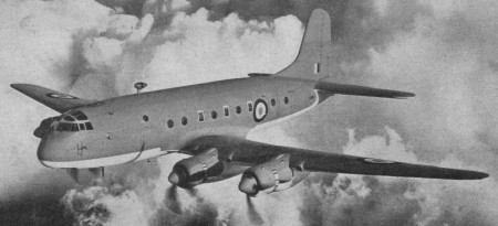
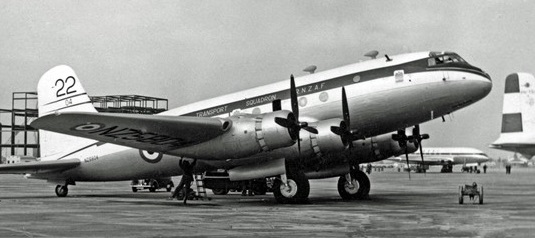
The Hastings was a general-purpose long-range transport flown by the RAF and RNZAF. Its roles included those of freighter, paratroop-transport, ambulance, troop-carrier, supply-dropper, jeep-carrier and glider-tug, first flown on May 7, 1946.
The initial production version was the C.1, first flown on 25 April 1947 and powered by four Bristol Hercules 101 engines. All C.1s were subsequently modified to Mk 2 standard and redesignated C.1As. The C.2 was powered by four Hercules 106 engines, had the tailplane lowered to the centreline of the fuselage and increased in area, extra fuel tanks, and the crew rest station replaced by an air-quartermaster post. The Hercules 737-powered C.3 was similar to the Mk 2 – and four were supplied to the RNZAF.
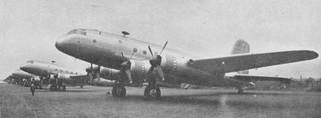
Hasting C.3
Two RAF squadrons of eight aircraft each went into service on the Berlin Airlift.
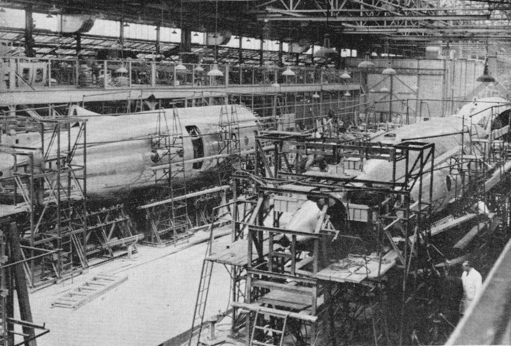
RAF Hastings assembled at Radlett in 1948
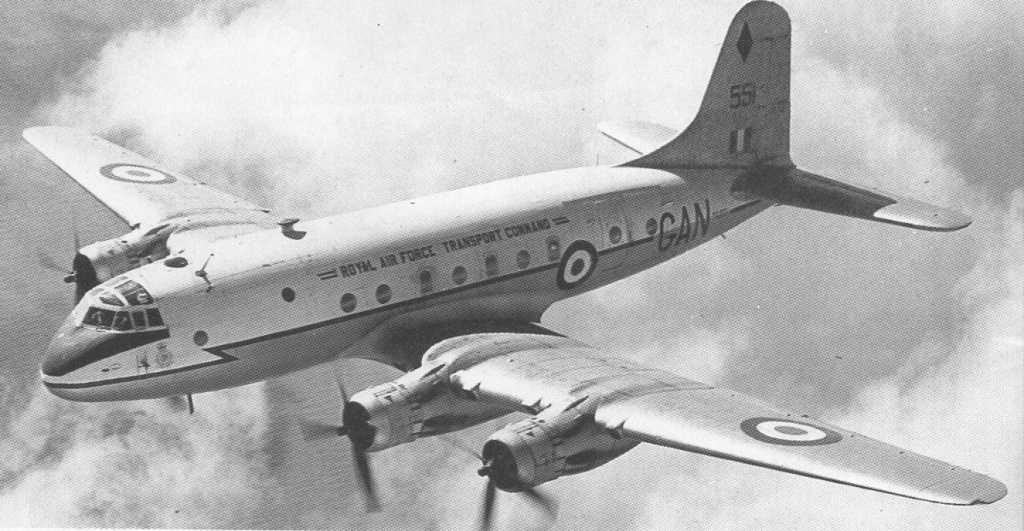
The final version was the C.4, a VIP version of the Mk 2 with accommodation for four VIPs and staff. Four were delivered to RAF Transport Command, bringing the total number of Hastings operated by the RAF up to 147. The last Hastings were withdrawn from service in 1968.
Hastings C.2 Engines: 4 x Bristol Hercules 106, 1249kW Max take-off weight: 36280 kg / 79984 lb Empty weight: 21960 kg / 48414 lb Wingspan: 34.44 m / 112 ft 12 in Length: 25.20 m / 82 ft 8 in Height: 6.86 m / 22 ft 6 in Wing area: 130.80 sq.m / 1407.92 sq ft Max. speed: 560 km/h / 348 mph Cruise speed: 486 km/h / 302 mph Ceiling: 8075 m / 26500 ft Range: 2720 km / 1690 miles
C.3 Engines: 4 x Bristol Hercules 737, 2040 hp. MAUW: 83,000 lbs. Max speed: 350 mph.
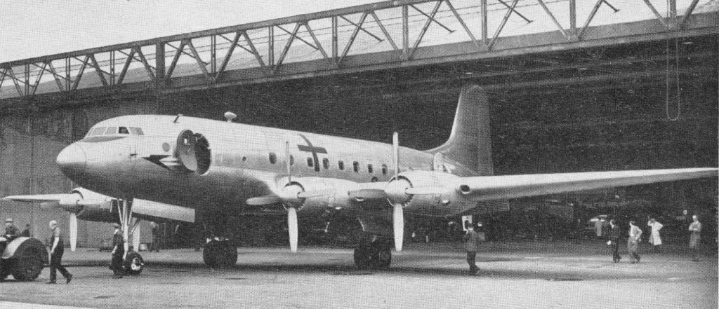
Designed during the Second World War for future peace time routes, the Hermes was dogged by misfortune and delays. The initial prototype of 1945 stalled and crashed, and it was not until August 1947 that the definitive Hermes 2 passenger version flew.
The Hermes 2 development aircraft had the tailwheel undercarriage of the Hastings but a lengthened fuselage.
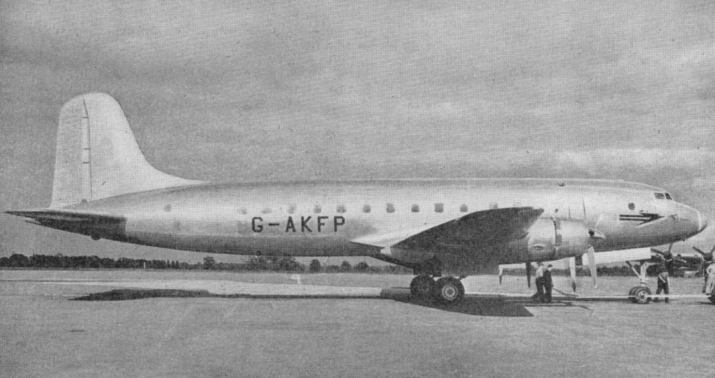
On 19 March 1947 production was authorised for 25 pressurised HP.81 Hermes IVs for BOAC, with nose wheel.
Hermes 4
The Hermes IV was assembled in 73 days. Britain’s first large civil transport with a nosewheel, was pressurised, and held up to 63 passengers.
1948
The Hermes IV made its first flight from Radlett on 5 September 1948 in the hands of H.G. Hazelden. The first flight was for 75 minutes. A second flight was of about 4 hours.
Loss of the prototype dented confidence but Farnborough 1950 saw the Mk.5 second prototype G ALEV featuring slotted flaps, increased all up weight and a fuselage very high above the ground which necessitated what for the period were very high steps.
The Hermes 4 was the first British post-war airliner built to modern standards to go into service; 25 were delivered to BOAC for use on its Commonwealth routes, services beginning in August 1950. Normal accommodation was for 40 passengers, but alternative seating arrangements provided for a maximum of 74. Originally powered by four 1,565kW Bristol Hercules 763 radial engines, all were subsequently re-engined with 1,583kW Hercules 773s and were then known as Hermes 4As. It was replaced by Canadian C 4s in 1952.
Hermes IV Engines: 4 x Bristol Hercules 763, 1566kW / 2,100 hp Max take-off weight: 39000 kg / 85981 lb Empty weight: 25100 kg / 55336 lb Wingspan: 34.44 m / 113 ft 0 in Length: 29.51 m / 96 ft 10 in Height: 9.14 m / 29 ft 12 in Wing area: 130.80 sq.m / 1407.92 sq ft Max. speed: 563 km/h / 350 mph Cruise speed: 435 km/h / 270 mph Ceiling: 7470 m / 24500 ft Range: 3200 km / 1988 miles with 14,000 lb (6,350 kg.) payload Seats: 5 crew; 40 passengers
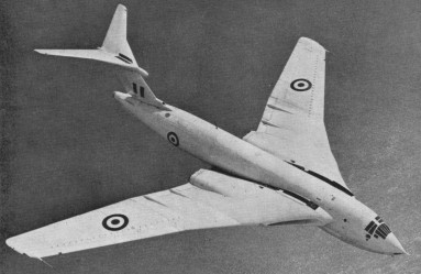
With the intention that the RAF should provide Britain’s strategic nuclear deterrent, design work began at Handley Page in 1947 on a long-range four-engined medium bomber that would be able to carry nuclear or conventional weapons internally. The Victor was the last of three V-bombers (named by Sir Winston Churchill) to enter RAF service, preceded by the Valiant and Vulcan.
Godfrey Lee presented his ideas to Sir Frederick Handley Page (FHP), who in 1945 had requested a study for a jet bomber to replace the Avro Lincoln. In February 1946 Lee came up with a futuristic design with a 45 degree swept wing of 122ft span, with wingtip fins and only a small trimming tailplane. Designed to carry a 10,000lb atomic bomb at 520kt over 5,000 miles, it had four axial-flow turbojets. A brochure was prepared and design number 80 allocated. The Air Ministry responded with Air Staff Operational Requirement OR.229, calling for a radius of action of 1,500 nautical miles (n.m.) with a 10,000 lb bomb, and a cruising speed of 500kt at heights from 35,000 to 50,000 ft. An amendment increased the range to 5,000 miles and minimum altitude to 50,000 ft.
This requirement became Specification B.35/46 of March 1947. Handley Page tendered the H.P.80, and was told at the end of July that an order would be placed, along with one for the Avro 698.
To keep the lift:drag ratio high to get good range, the span had to be fairly large, and the average chord fairly small. The aspect ratio came out at about 8:1, rather high, which suggested that the wing would be relatively heavy. The sweep at the wing root would have to be 50 degrees.
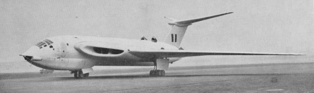
Victor K.2
A model of the initial wing design was tested in a high-subsonic speed wind tunnel at the Royal Aircraft Establishment (RAE) at Farnborough. Disappointingly, the drag-rise Mach number was shown to be only about 0.8, mostly due to the outer parts of the wing. However, the modified wing was much better, mainly due to the effective thinning down of the outer panels owing to their extended chord. Additionally, the wingtips were given a special round shape, again to maintain high sweep of the isobars.
The Victor’s flying controls would have to be capable of operating at high Mach numbers and with large applied air loads. The decision was made to go to fully-powered electro-hydraulic operation. The only connection between the flying controls and the pilots’ controls in the cockpit was via an operating valve. When the pilot moved the column the valve allowed fluid at high pressure to enter a hydraulic actuating jack, moving the control surfaces. To cope with a failure, the control units were duplicated and independent of the aircraft’s hydraulic system.
One innovation was the airbrake installation in the rear fuselage. This comprised a pair of large shaped plates, hinged to open out on either side of the fuselage at any angle up to about 60 degs. Actuated by a single hydraulic jack inside the rear fuselage, they gave a lot of drag either to slow the aircraft down or to adjust the approach angle when landing. They were found to work well.
The Victor’s wing structure was based on three mainspars which carried the major loads. Sandwich panels that took internal pressure and fuel loads had supporting local spars. There were relatively few ribs, but those at the root and kinks were massive, and were joined, flange to flange, by what were termed “pipejoints ‘. Thus the wing could be built in three portions per side, and was relatively easy to transport.
The wing was essentially a “multi-load-path” component, having sandwich panels and multiple webs. The webs, with spanwise corrugations, withstood spanwise endload due to bending, shear due to wing torsion and chordwise end loads due to tank pressure and air loads.
The panels consisted of an inner and outer skin separated by about an inch by corrugations, this core also making a contribution for end load and shear. Spot welding was used to attach the outer skin to the core, and the inner skin was attached by blind rivets.
The spars at the root were swept well forward to where the wing was at maximum thickness, enabling the engines to be mounted on sub-structure behind them. This made engine removal quite easy. Sandwich panels were used here as cover, but the corrugations ran chordwise so that they did not take up wing bending end loads, carried by the spars at this point. The lower surface mainly comprised engine and undercarriage doors.
The mid-set wings have compound sweepback, varying from 52.2 deg on the inner wings to 35.2 deg on the outer.
Five years would elapse from acceptance of the basic idea to the maiden flight of the first Victor prototype, W13771, on 24 December 1952 at the Aeroplane & Armament Experimental Establishment (A&AEE) at Boscombe Down with test pilot H.G.Hazelden, and another five years would be spent in development and flight testing before the RAF took delivery of its first production Victor.
The prototype H.P.80 remained at Boscombe Down until runway lengthening at Radlett had been completed, although Handley Page employees at Radlett and Cricklewood were given their first glimpse of the aircraft in the air when it flew over during one lunchtime, the staff having been advised of the event earlier in the day. The first official public appearance of the Victor was in the flypast at the Queen’s Coronation Review at Odiham onjuly 15, 1953, and in September that year it appeared at the SBAC Exhibition at Farnborough in a rather sinister black, red and silver colour scheme. Disaster struck on July 14, 1954, however, when WB771 suffered a fatal flutter incident at Cranfield, resulting in the loss of test pilot “Taffy” Ecclestone and all the crew. By then the second prototype, W13775, was ready to continue flight development.
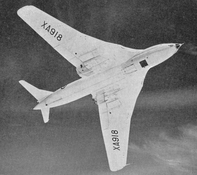
The production Specification, B128P, had appeared in August 1952, but it was not until February 1, 1956, that XA917, the first production aircraft made its first flight from Radlett, followed by the second, XA918, some seven weeks later. Retained by Handley Page for development flying, XA917 was never used in RAF squadron service. It had the distinction of reaching supersonic speed for the first time, in a dive, on June 1, 1957, the largest aircraft to have done so in the UK. It ended its flying career in 1960, after nearly 500hr flight time on 222 test flights. The fifth production aircraft, XA921, was finished in an all-white scheme that was to become standard for Victors for several years. It was exhibited on the ground at Marham for the Queen’s Review of Bomber Command on July 23,1957. Groundschool for Victor personnel in the RAF started when “A” Flight of No 232 Operational Conversion Unit (OCU) was disbanded in December 1956 for the unit to attend at Radlett. This lasted nearly a year, the Flight re-forming and receiving its first Victor at the end of November 1957, about two years after the desired date for entry stated in operational requirernent OR.229. The first squadron to operate the Victor BI was No.10 Sqn at Cottesmore, re-formed on April 1, 1958; the 40th anniversary of the formation of the RAF. TheVictor, in its several marks, was to stay in RAF service for almost as long again. Next came 15 Sqn, in September, followed by 57 Sqn on New Year’s Day 1959.
Note worthy was one flight from Farnborough to Lucia, Malta, a distance of 1,310 miles, covered in 2hr (October 14, 1958), and another from Goose Bay, Canada, to Marham, 2,020 miles, in 3hr 8min (October 20,1958).
The B.I remained in service as a part of Britain’s nuclear deterrent into the early-to-mid-1960s, being replaced by the B.2, but midway through 1964 the in-flight-refuelling tanker version of the Valiant, the first of the V-bombers, was found to be suffering from fatigue cracking of major structure, necessitating its rapid withdrawal.
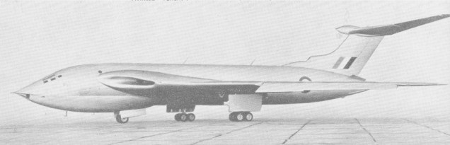
Victor B.2
To fill the gap in capability created, designs were urgently prepared for the conversion of some of the Victor Mk 1 s to take over the task. Six were returned to Radlett to have underwing refuelling pods fitted. This was an interim solution; the pods were suitable for fighters, but larger aircraft needed a bigger unit which was to be fitted into the bomb bay just aft of the wing root trailing edge, along with extra fuel tanks. The “two-point tankers” retained the ability to revert to bombing at fairly short notice, and became operational at Marham in May 1965. They were followed by the “three-point tankers” starting in November 1965, 57 Sqn becoming operational with them in June, 1966, followed by Nos 216 and 55 Sqns.
When the Victor Mk2 was designed, the span was increased by adding an 18in-wide strip of wing at the root, and by moving the wingtips out 42in, giving a 10ft increase in span. By then research had shown that, if the nose of the outer wing sections could be extended forwards by a relatively small amount and given a carefully designed downwards camber, they gave acceptable behaviour at high lift and improved turning characteristics at high speed. The modification was retrospectively applied to the Mk 1 when it was converted as an inflight refuelling tanker, making it the Mk 1A. The accumulator and its associated equipment were dispensed with; a significant weight saving.
A single large weapon bay was provided, and could carry 35 bombs of 454 kg (1,000 lb).
Strength tests of complete airframes, carried out in the test rig at Park Street Test House at Radlett airfield, confirmed that the aircraft’s strength met all the structural requirements of the specification. Even when necessities during the Mk 2’s Service life meant it had to be operated at low altitude, an environment for which it was not designed, it was found to be able to perform that duty adequately, though the structure became “fatigued” more quickly. This had a big influence when it came to the conversion of the Victor B.2 to take over tanker duties from the Mk 1, and special measures had to be taken to ensure that the “fatigue life” usage was kept to a minimum and spread throughout the fleet.
The air intake ducts were fed between the top and bottom booms of the spars. The carrythrough box across the fuselage was very large, taking out the wing root bending and torsion.
The flaps and ailerons were carried on sub-spars with large flap tracks for the large Fowler type area-increasing flaps. These first moved backward with little rotation to give a relatively low-drag, high-incremental-lift position for take-off, and then moved further still and rotated to give the higher lift, higher drag for approach and landing.
Early Victors had hinged nose flaps at the outerwing leading edges, but these were superseded by fixed, drooped leading edges also carrying “turbulators” which helped to stabilise the flow round the leading edges. The main fuselage was of fairly conventional skin, stringer and frame construction, but the 32ft-long bomb bay occupied most of the fuselage aft of the main wing carry-through box. The top consisted of D-section frames, between which were mounted bag-type fuel tanks, three of the frames being strengthened to carry bomb loads and hoisting points, and ending at a bulkhead taking the front spar of the fin. Strong longerons ran along the bottom of each sideJust above the sliding bomb-bay doors. The tailcone housed a large hydraulic jack that operated the large fully-variable air brakes on each side of the rear fuselage. On top, behind the rudder, was the container for the 45ft ring-slot braking parachute.
Each eight-wheel main undercarriage bogie, housed between two heavy ribs outboard of the engines, folded forwards as it retracted. It had anti-skid brakes. The twin nosewheels were steerable but unbraked.
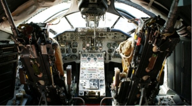
The crew was housed in a pressure cabin designed to a pressure differential of 9 lb/sq.in and having a sloping windscreen. The pilots had dual controls and Mk 3 ejection seats, and sat ahead of and slightly higher than the rear crew, who sat on three swivelling seats in a row. Adjacent to them, on the port side, was the crew entry door. In an emergency this opened outwards, and had a shield to protect emerging crew members. A periscope was fitted for inspecting the wing undersurface and checking if telltale vapour trails were being formed. In the tankers it was used to study the behaviour of receiver aircraft.
Production aircraft had a refuelling probe above the windscreen, in good view of the pilots. Underneath the floor of the cabin was the main radome.
The first prototype made its maiden flight on 24 December 1952. The first production Victor flew for the first time on 1 February 1956. The first production B.1, each with four 48.93kN (11,000 lb) thrust Armstrong Siddeley Sapphire 201 turbojets began to enter RAF service with No 232 Operational Conversion Unit in November 1957. The first Victor squadron (No 10) became fully operational at Cottesmore in the spring of 1958. Formation of the planned total of four Victor B.1 squadrons was completed early in 1960. B.1A aircraft had ECM and other equipment changes.
The Mk 1 had four Armstrong Siddeley (later Bristol Siddeley) straight axial-flowjet engines at Sa7 rating, each giving 11,0001b static thrust at sea level. They were mounted in pairs, sharinga common air intake in the wing leading edge, individual ducts leading to each engine. The orifices at the wing trailing edge were canted slightly outwards. While the Sapphires were perfectly adequate for take-off at normal operating weights, they were marginal in overload cases. Removable underwing de Havilland Spectre rocket assistance units gave a spectacular improvement, but were rather impractical. There is no record of their use in service. The Mk 1 s had to be carefully operated in “hot and high” conditions, at some risk when heavily loaded. Many hours of research were needed to achieve an efficient engine intake. The Mk 1’s Armstrong Siddeley Sapphire engines had a design of axial compressor which was unaffected by the flow distortion that was inevitable given the intake type, but the Rolls-Royce Conways of the Mk 2 were much fussier, and drastic changes had to be made to the intakes, involving a duct of greater cross-section and flow-governing internal vanes. The fin was a conventional two-spar structure with corrugated skins, but the dihedral tailplane, carried atop the fin, was very nearly “all-moving”, with just a stub tailplane housing the elevator powered flying control units. Its construction was similar to that of the wing. The flying controls, elevators, ailerons and rudder had operating jacks driven by duplicated hydraulic motors, each being powered by its own electric motors and signalled by slide valves connected to the pilot’s controls. They were irreversible, and there was no manual reversion in the event of failure. On the Mk 1 four engine-driven alternators provided 73 KVA electrical power, transformed to 112 and 24V DC with four 24V batteries. inverters were used to supply AC to various equipments. Two hydraulic pumps, powered by 11 5V DC electric motors, supplied 4,000 lb/sq.in to work the undercarriage, flaps, airbrakes and bomb doors, and the fuselage Mk 17 hose drum unit (HIDU) on the tanker version. The span was increased by 10ft for the Mk 2. Streamlined half-bodies on the rear top surface of the wing at about mid-semi-span, called “Whitcomb Bodies” or “Kuchemann Carrots”, housed containers of Window anti-radar strips. Inspired by research by Richard T. Whitcomb of NASA in the USA and Dietrich Kuchemann at RAE Farnborough, they increased the drag-rise Mach number at the cost of a little skin-friction drag. The Sapphires were replaced by Rolls-Royce Conway bypass engines, initially Mk 10301s at Co.11 rating (17,5001b static sea level thrust), then by Co.17s, Mk 20101s of 20,000 lb-thrust. The higher thrust allowed a significant increase in all-up-weight. Although the Conway’s sea-level thrust was approximately double that of the Mk I’s Sapphire, it fell off more rapidly at high altitudes, despite fuel consumption per pound of thrust being better. The Conway required a much greater throughput of air, however, and the intakes had to be considerably enlarged and fitted with flow straightening vanes before the engine ran properly. A Bristol Siddeley Artouste auxiliary power unit was installed in the Mk 2’s starboard wing root, driving a 40KVA alternator. It could be used in flight up to 25,000ft and, because it could be started on the aircraft batteries, made the aircraft independent of ground services. The electrical system now relied on four 40KVA (later 50KVA) 200V alternators at 400Hz, with transformers to provide 11 5V AC and rectifiers for 24V DC. Two ram-air turbines in the upper rear fuselage, with intakes that opened automatically at low airspeeds, provided 15KVA AC each for the powered flying control units in the event of electrical failure. The first Victor B.2, XH668, initially with lower-power Conway 11s, made its first flight on February 20, 1959, but disaster struck once again when it disappeared over the Irish Sea on August 20 with its A&AEE and H.P. crew. As the Victor was so important to Britain’s nuclear deterrent, huge efforts were made to recover as much wreckage as possible to determine what went wrong. About 75 per cent of XH668 had been dredged up by the end of 1960. After a searching investigation by RAE Farnborough the problem was attributed to the loss of a wingtip pitot-static tube, which then caused a nose-down runaway of the Mach-trimmer system. Although this was the official verdict, many people did not think it was the right one. The company’s test pilots had made tests in which the trimmer was deliberately made to run away, and had reported that this could very easily be compensated for. Many years later a senior RAF officer stated that he knew the real answer, but was not permitted to disclose it.
Whatever the cause, the second aircraft, XH669, which had made its maiden flight a few days before the accident, then undertook the burden of Mk 2 development flying. It appeared at the SBAC Display in September 1960, and was joined by XH670,’67l,’672 and’673 in tests of new equipment. On December 5, 1960, XH673 was engaged in highaltitude tests of the hydraulic system when the system failed. Although the flying controls still worked, the bomb doors were partly open, and the flaps, airbrakes and wheels could not be extended.john Allam, H.P.’s chief test pilot and captain of the aircraft, diverted to RAF Waddington, calling the fire service there to lay a foam runway for a wheels-up landing. This was a speciality of the station, which had done it for an in-service B.1 two years earlier.
Allam made a perfect touchdown after a flapless approach, but ran out of foam before the aircraft came to rest. The friction caused a small fire, which was quickly extinguished. No-one was hurt, and the aircraft was repaired and used for trials at Boscombe Down in April 1961.
The B.2 entered service with the No 139 Squadron RAF on February 1, 1962, when 139 (Jamaica) Sqn at Wittering received XL231. These had more powerful engines, increased wing span, enlarged air intakes, and introduced a “Window'”dispenser pod on the trailing edge of each wing. In late 1962 the process of returning B.2s to Radlett began under a retrofit programme to install more sophisticated equipment and the fully-rated Conway 17 engines.
Some aircraft were also equipped for carriage of the Blue Steel air-launched rocket-powered stand-off missile with a nuclear warhead, which was released short of its intended target, well clear of any heavily defended area, and made its own way to the target at supersonic speed. These Victors were designated B.2R. No 139 Squadron was the first to become operational with the Blue Steel nuclear stand-off bomb in February 1964. Victor squadrons were subsequently specified for low-altitude in addition to high-altitude attack.
Such was the pace of technical improvements in defence capability that the airborne delivery of nuclear weapons was becoming too uncertain of success by the late 1960s.In its place the launch of intercontinental ballistic missiles from hardened shelters or submarines was chosen. Thus the B.2Rs were phased out as bombers, starting in 1968, and flown back to be stored at Radlett.
There were strategic reconnaissance Victor SR.2s in service, equipped with a battery of high-resolution cameras in the bomb bay, flanked by long-range tanks. Victor B(SR).2 strategic-reconnaissance aircraft entered service with No 543 Squadron at RAF Wyton in the autumn of 1965. These aircraft had the capability to radar map an area of up to 1,942,490sq.km during a six-hour period.
The Vickers Valiant tanker fleet was withdrawn at the end of 1964, leaving the RAF without support for its English Electric Lightnings and Gloster Javelins. However, a three-point tanker version of the Victor B.1 had been agreed earlier. The choice of the Victor had been in the balance in 1962, since it was said that it would not be possible to formate two Lightnings behind it. Handley Page’s RAF liaison officer, Gp Capt “Rosie” Leigh Houlbrook, arranged for a couple of Lightnings to demonstrate that they could do so with no problem.
Thus in 1964 some aircraft were already being stripped down at Radlett, and it was decided as a matter of urgency to convert six B.1As (XH615,’620,’667,’646,’647, andm’648) to a two-point configuration (underwing Mk 20 HDUs only, on standard RAE pylons). The first two were delivered in April 1965, the other four soon after, and they carried the burden well until the three-point K.1 and K.1A versions (fuselage HDU added) started arriving in 1967.
It was decided to convert ten aircraft from the XA serial range and 14 from the XH range to K.1A standard (fixed leading-edge droop in place of noseflaps). Considerable work was required: bomb-doors were removed, bomb-bay tanks were installed and the retractable Mk 17 HDU was installed in the rear of the bomb bay. The Sapphire 201s were replaced by 207s with engine-mounted alternators.
Hawker Siddeley Aviation was awarded the Victor B.2 tanker conversion contract after H.P. ceased trading in 1970, and the 21 B.2s on the airfield at Radlett had to be refurbished to a flyable state. They were then flown to Woodford, near Manchester, for conversion. Some were in poor condition; at least one had to be flown to Woodford at low speed with its undercarriage down. The wing and fuselage HDUs and associated fuel systems were installed, in a very similar fashion to the K.1, and the large underwing tanks were made nonjettisonable. Each aircraft had to be stripped completely to remedy corrosion that had started during long storage in the open, and had to be brought up to the latest modification standard. The outer wings were strengthened and the extended tips of the B.2 were replaced by the original B.1 tips. The ailerons were set up by a small amount, and modifications were made to the flying controls. The avionics fit was revised. With the aircraft reduced to its main components, refurbishment was carried out at several locations – Chadderton, Bitteswell and others. What was effectively a rebuilt aircraft was finally assembled at Woodford and flight-tested. The process took between two and three years. The first K.2, XL231, first flew from Woodford on March 1, 1972, although it was not fully modified structurally. Reducing the span by cropping the wingtips, to reduce the bending stresses, and setting the aileron trailing edge up on both sides certainly moved the centre of lift inboard, but the wing was swept, so the change also moved it forwards, closer to the c.g., rendering the aircraft less stable. Changing the stick-gearing to the elevators partly compensated but, when he flew the K.2 many years later John Allam remarked that he thought it unduly sensitive, and, had he been in charge, would not have asked the A&AEE to accept it.
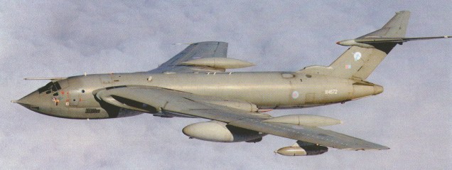
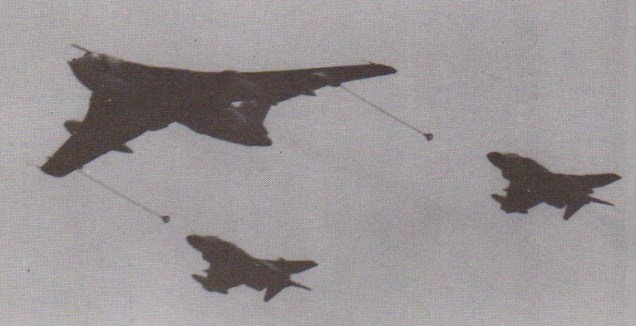
Victor K.2
It had a crew of five, and was powered by four Rolls-Royce Conway turbofans of 20,600 lb thrust each. It had a maximum speed of 640 mph (Mach 0.92) at 40,000 feet, a ceiling of 59,000 feet and a range of 3,500 miles. The changes also reduced the lift:drag ratio, giving a poorer cruise performance. But the RAF was desperate for the tanker, and it was accepted in that state. The first was delivered to the RAF on 8 May 1974. The first aircraft to enter service was XL233, and 23 others were eventually converted. They at once embarked on a regular routine of support for fighters sent out over the North Sea to investigate prowling Soviet aircraft, and also to accompany aircraft out to places such as Cyprus for regular exercises. As a tanker, the Victor is equipped with 32 separate fuel tanks carrying 55 tons of fuel, and three refuelling hoses, two on outer wing pods capable of delivering 682 lt/min, and a hose drum unit under the fuselage able to deliver 2273 lt/min. All this showed the value to the RAF of the Victor tanker, particularly when Argentina invaded the Falkland Islands on April 2,1982. In just over two weeks six aircraft were detached to Ascension Island, from where they could meet incoming supply aircraft. They also carried out a wide radar reconnaissance of South Georgia before its recapture. Victor Mk 2s were finally withdrawn from service in 1993, some three decades after they were introduced, and nearly four after the Mk 1 entered the RAF inventory – a massive achievement and tribute to the H.P. team behind the Victor’s design and development.
XH668 Crashed into Irish Sea during trials, 20 August 1959
XL159 Crashed at Stubton near Newark, Notta, in superstall, 23 March 1962
XM714 Stalled after takeoff at Barnack, near Stamford, Linc, 20 March 1963
XM716 Crashed at Warboys, Cambs, after being overstressed in press demonstration, 29 June 1966
Victor B.2s cancelled 28 aircraft XL250-XL255, XM745-XM756, XM785-XM794
Specifications
HP.80 Wingspan: 110 ft Lengrh: 98 ft 2 in Wing area: 2406 sq.ft Wheel track: 30 ft 2 in Max takeoff weight: 120,000 lb Max speed: 594 mph at 36,000 ft Range: 6000 miles Aspect ratio: 8:1 Sweep at the wing root: 50 degrees Cabin pressure: 9 lb/sq.in
B.1 Engines: 4 x 48.93kN (11,000 lb) thrust Armstrong Siddeley Sapphire 201 turbojets Wingspan: 110 ft Lengrh: 102 ft 5 in Wing area: 2406 sq.ft Wheel track: 30 ft 2 in Basic weight: 89,030-90,100 lb Operating weight: 92,228-94,048 lb Max takeoff weight: 170,000-185,000 lb Max speed: 627 mph at 36,000 ft Service ceiling: 55,000 ft Range: 6000 miles
B.1A Engines: 4 x 48.93kN (11,000 lb) thrust Armstrong Siddeley Sapphire 201 turbojets Wingspan: 110 ft Lengrh: 102 ft 5 in Wing area: 2406 sq.ft Wheel track: 30 ft 2 in Basic weight: 89,030-90,100 lb Operating weight: 92,228-94,048 lb Max takeoff weight: 170,000-185,000 lb Service ceiling: 55,000 ft Range: 6000 miles
B.2 Engines: 4 x Rolls-Royce Conways Mk 10301, Co.11 rating 17,5001b static sea level thrust later Co.17s, Mk 20101, 20,000 lb/9,344 kg -thrust. Wingspan: 120 ft / 36.6 m Length 114.9 ft / 35 m Height: 30 ft 1.5 in / 9.18 m Wing area: 2597 sq.ft Wheel track: 33 ft 2 in Empty weight: 41270 kg / 90985 lb Basic weight: 107,950 lb Max takeoff weight: 187,000 lb Max speed: 647 mph at 36,000 ft Normal cruise Mach 0.92 Max cruise alt: 55,000 ft / 16,750 m Service ceiling: 60,000 ft Range: 6000 miles Combat radius: 2,300 miles / 3,700 km Max. bomb load: 35,000 lb / 15,875 kg Crew: 5
B.2R Engines: 4 x Rolls-Royce Conways Mk 10301, Co.11 rating 17,5001b static sea level thrust later Co.17s, Mk 20101, 20,000 lb/9,344 kg -thrust. Wingspan: 120 ft / 36.6 m Length 114.9 ft / 35 m Height: 30 ft 1.5 in / 9.18 m Wing area: 2597 sq.ft Wheel track: 33 ft 2 in Max. bomb load: 35,000 lb / 15,875 kg / 1x Blue Steel (nuke) Crew: 5
SR.2 Engines: 4 x Rolls-Royce Conways Mk 10301, Co.11 rating 17,5001b static sea level thrust later Co.17s, Mk 20101, 20,000 lb/9,344 kg -thrust. Wingspan: 120 ft / 36.6 m Length 114.9 ft / 35 m Height: 30 ft 1.5 in / 9.18 m Wing area: 2597 sq.ft Wheel track: 33 ft 2 in
K.1A Engines: 4 x Rolls-Royce Sapphire 207
K.2 Engines: 4 x Rolls-Royce Conways Mk 10301, 20,600 1b static sea level thrust later Co.17s, Mk 20101, 20,000 lb-thrust. Wingspan: 117 ft Wing area: 2580 sq.ft Wheel track: 33 ft 2 in Basic weight: 115,400 lb Operating weight: 224,500 lb Max takeoff weight: 223,000 lb Max speed: 640 mph / M0.92 at 40,000 ft Ceiling: 59,000 ft Range: 3500 miles Fel capacity: 55 ton Aerial refueling stns: 3 Refueling flow; 2 at 682 lt/min / 1 at 2273 lt/min Crew: 5
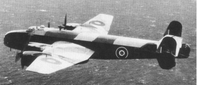
The four engined bombers, the Halifax, Stirling and Lancaster, all originated from a pre war Air Ministry specification. The Handley Page Halifax was first flown on 25 October 1939 from RAF Bicester with four “Merlin X” engines.
Originally designed for two Rolls-Royce Vulture engines, the Halifax eventually flew with four Roll-Royce Merlins.
Prototype with four Merlin 10 engines and no dorsal turret
Entering production in 1939, it was the second British four-engined bomber to enter service in the Second World War, with 35 Squadron on 13 November 1940. The first Halifax raid by the squadron was against le Havre, France, on 10 March 1941. The Halifax was the first to bomb Germany when one took part in a raid on Hamburg on the night of 12-13 March 1941.
The Halifax shared with the Lancaster the major burden of Bomber Command’s night bombing campaign against Nazi Germany but the Halifax was used extensively on other duties including glider-tug, agent dropping transport and general reconnaissance aircraft in Coastal Command.
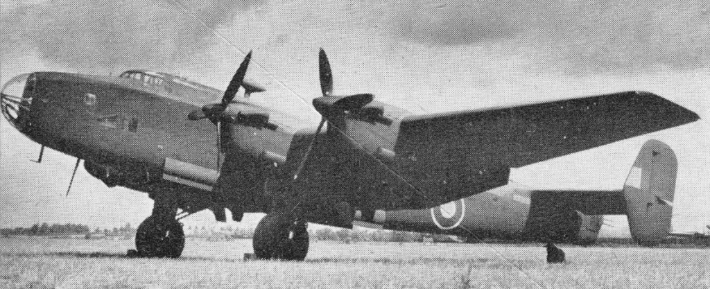
Halifax B.2 Srs.1A
The Halifax B.2 was powered by Merlin 20 and fitted with a Hudson dorsal turret, and the B.2 Srs.1A with a nose turret.
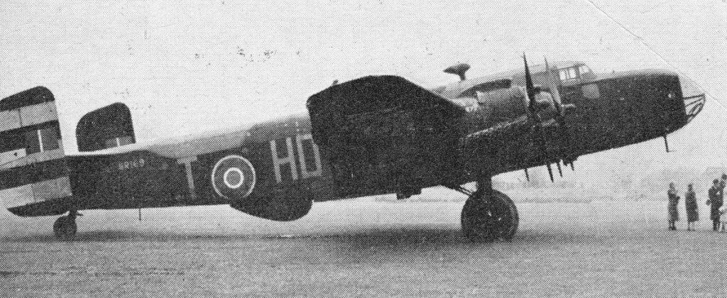
Halifax B.2 Srs.1A
The B.2 Srs.1A had the nose turret deleted and was fitted with a Defiant dorsal turret.
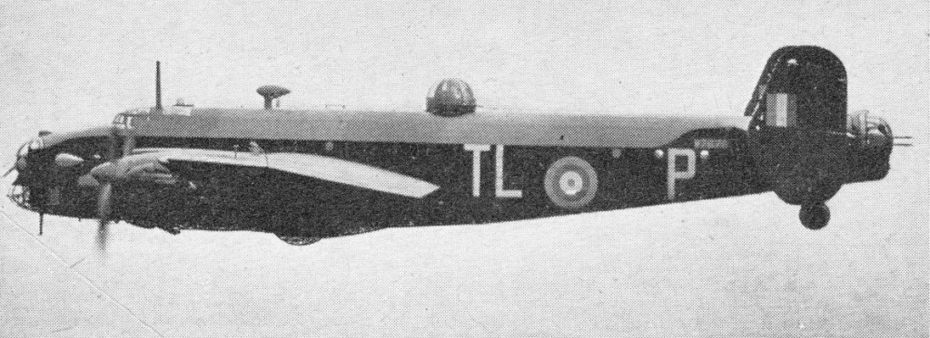
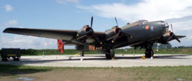
HP.66 Halifax M.6
The Halifax Mk.6 was powered by Hercules 100 engines, had squared fins, H2S radar and increased span.
However, between 1941 and 1945 the Halifax made 75,532 bombing sorties and dropped 227610 tons (231300 tonnes) of bombs; more than a quarter of all bombs dropped on Germany by the Royal Air Force.
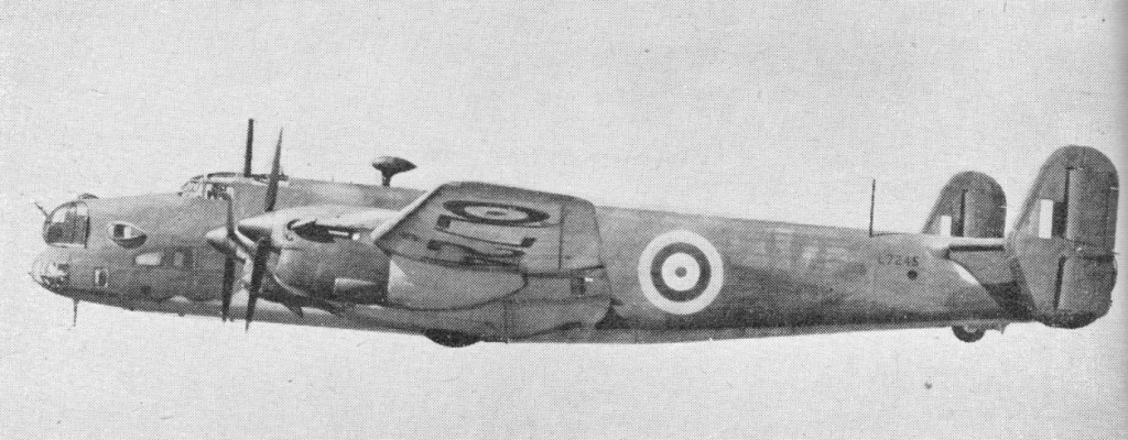
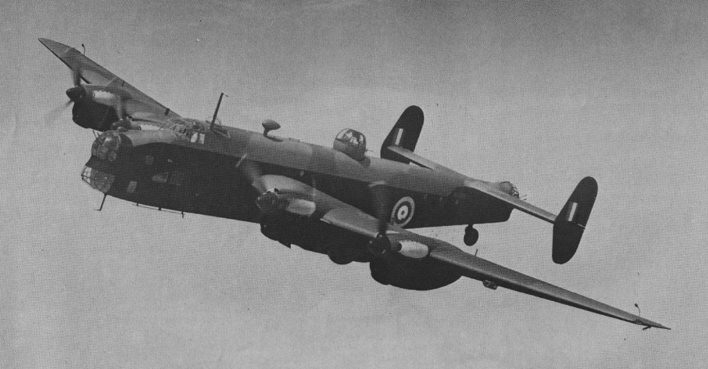
Handley Page Halifax II(III)
The Halifax I and II aircraft were powered by Rolls-Royce Merlin engines and the Halifax III was powered by Bristol Hercules engines. Apart from the role as a heavy bomber, the Halifax III and later versions also served in Coastal Command and in paratrooping and glider towing roles with the Airborne Forces.
Halifax II
Due to mounting losses on Bomber Command operations over Germany Halifax bombers were restricted to less hazardous targets from September 1943.
The Halifax was in the process of being replaced as a front line bomber in 1945 but it continued in service with Coastal and Transport Commands after the war. The last operational flight was made by a Coastal Command Halifax in March 1952 while operating from Gibraltar.
Halifax production totalled 6,178, including 4751 bombers.
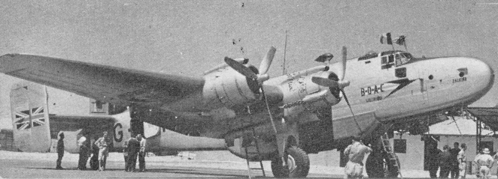
During 1946-48 more than 90 Halifax were converted to civil transport Halton variants. The HP.70 Halton were derived from the Halifax C.8 for BOAC immediately after WW2.
Mk.II Engines: 4 x RR Merlin XX. Max speed: 282 mph Range: 1030 miles Crew: 7 Armament: 9 x .303 Browning mg Bomb load: 13,000 lb
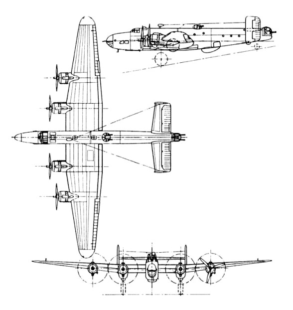
Handley Page HP 57 Halifax B Mk III Engines: 4 x Bristol Hercules XVI, 1615 hp Length: 70.079 ft / 21.36 m Height: 20.735 ft / 6.32 m Wingspan: 98 ft 10 in , later 104 ft 2 in / 31.75 m Wing area: 1274.996 sq.ft / 118.45 sq.m Max take off weight: 65012.2 lb / 29484.0 kg Weight empty: 38245.7 lb / 17345.0 kg Max. speed: 245 kts / 454 kph Cruising speed: 187 kts / 346 kph Service ceiling: 23999 ft / 7315 m Cruising altitude: 20013 ft / 6100 m Wing loading: 51.05 lb/sq.ft / 249.0 kg/sq.m Range (max. weight): 895 nm / 1658 km Crew: 7 Armament: 9x cal.303 MG (7,7mm), 5897kg Bomb.
Engines: 4 x Bristol Hercules 100, 1325kW Max take-off weight: 24980-30845 kg / 55072 – 68002 lb Empty weight: 17500 kg / 38581 lb Wingspan: 31.8 m / 104 ft 4 in Length: 21.4 m / 70 ft 3 in Height: 6.3 m / 20 ft 8 in Wing area: 118.5 sq.m / 1275.52 sq ft Max. speed: 502 km/h / 312 mph Ceiling: 7310 m / 24000 ft Range w/max.fuel: 3540 km / 2200 miles Range w/max.payload: 2030 km / 1261 miles Armament: 9 x 7.7mm machine-guns, 6550kg of bombs Crew: 7
To Imperial Airways fell the task of establishing British commercial air transport on an economic basis, and with government backing it became possible – at least in a modest way – to begin the procurement of new aircraft and the survey and inauguration of air routes to link the British Empire. Needing more capacity than was provided by its 18-20-seat Armstrong Whitworth Argosy or 14-seat Handley Page W.10 aircraft, Imperial Airways acquired from Handley Page eight aircraft designed specifically for use on the European and eastern sections of the Empire air routes.
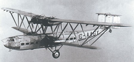
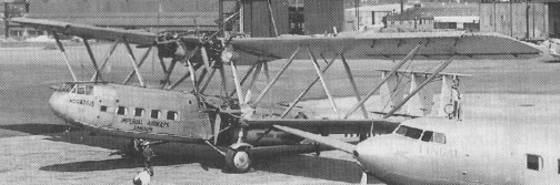
HP.42 Hannibal
Large biplanes, with a maximum wing loading of less than 48.2 kg/sq.m, they were of all-metal construction except for the aerofoil surfaces and aft fuselage, which were fabric-covered. The unequal-span biplane wings were devoid of flying and landing wires, braced instead by massive Warren girder struts, and having ailerons and Handley Page slots only on the upper wing. The tail unit was also of biplane configuration, with triple fins and rudders, and the heavy landing gear was of fixed-tailwheel type. Power plant comprised four supercharged Bristol Jupiter engines, two mounted on the upper wing and one on each side of the fuselage on the lower wing.
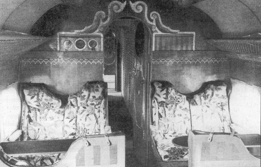
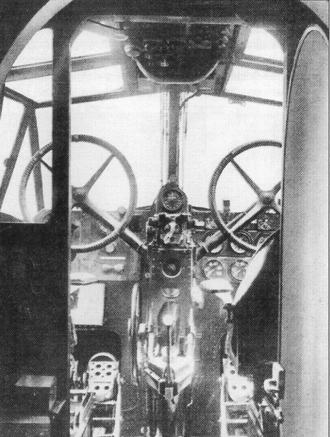
For the first time in any British airliner the crew were accommodated inside the aircraft, in a compartment high in the fuselage nose which we would now call a flight deck. Within the main cabins – fore and aft of the wing area where the engine noise originated – passengers were provided with completely new standards of comfort and spaciousness.
Only four of thes Handley Page H.P.42 were ever built, the biggest biplane aircraft ever built. First acquired by Air Transport and Travel, it first flew from London to Paris in 1919 with a single passenger on board – a newspaper reporter.
Those intended originally for eastern use (on the Indian and South African routes) carried six (later 12) passengers in the forward cabin and 12 in the rear, with space for 14.16cu.m of baggage and mail amid-ships. The four equipped for the European routes (based at Croydon) carried 18 passengers forward, 20 aft and had 7.08cu.m of baggage space. The first HP.42 flew on 14 November 1930. It was equipped subsequently for long-range service (H.P.42E, ‘E’ for Eastern) and named Hannibal.
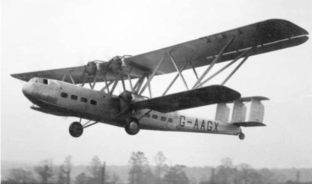
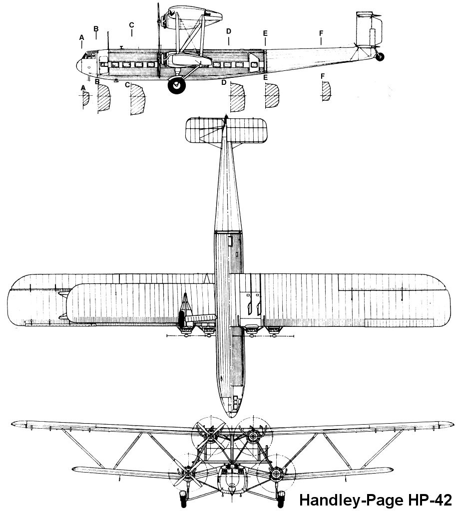
Handley Page H.P.42
Four Hannibal class H.P.42s, operated in semi-tropical conditions on the long eastern mail routes between Karachi, Cairo and Kisumu.
Anthony Fokker once commented that H.P.42s had built-in headwinds, but their cruising speed of around 161km/h, excellent handling at low speeds and robust structure ensured that they were able to boast a decade of fatal-accident-free flight before being withdrawn from civil airline service on 1 September 1939.
The H.P.42 was developed into two variants: the H.P.42E (Eastern) for long-haul routes to the middle East and beyond, and the H.P.42W (Western or HP.45) for imperial’s flights to Paris and other European cities.
The HP.42E served exclusively in the east, the four HP.42Ws were Croydon-based and differed by being configured for a maximum of 38 passengers, rather than the 24 of the HP.42E.
The HP.42W were first delivered in September 1931.
Hercules, the first HP.42W delivered, by 23 July 1937 had flown 1 million miles / 1.6 million km on routes to Paris, Cologne and Zurich. Just over a year later, it had completed s further 250,000 miles / 400,000 km and had carried 95,000 passengers.
The HP.42Ws were impressed into military service during World War II.
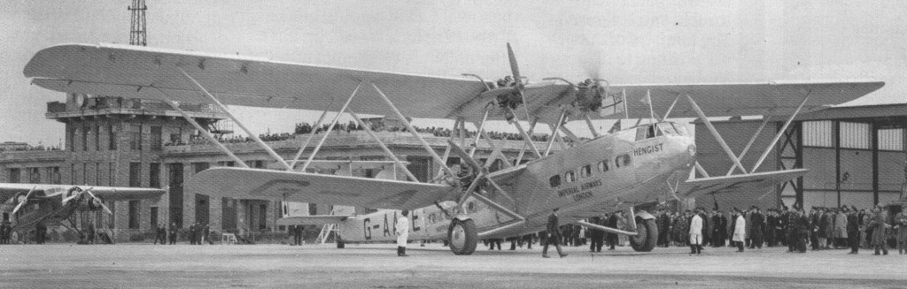
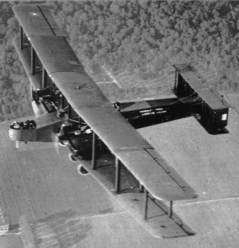
HP.45 Hercules
There were four Heracles class H.P.45s, used on Imperial Air¬ways western routes from Croydon to Europe. First of the H.P.42W (‘W’ for Western) for the European services was delivered in September 1931 and named Heracles. The two versions wore generally similar, except that the Heracles had 550 hp Jupiter X.FBM engines and accommodation for 38 passengers, whereas Hanni¬bal had Jupiter XIs of the same power and seats for only 18 passengers. The remainder of this family of 1930s ‘Jumbo’ airliners had the names Hadrian, Hanno, Helena, Hengist, Horatius and Horsa. Together they flew some ten million miles without ever hurting a passenger, until the last of them disappeared on a wartime flight in the Middle East. With their girder-braced biplane wings and massive fixed undercarriage they had a maximum cruising speed of about 100 mph (161 km/h), but offered standards of comfort and safety that no other transport of the period could equal. As a result, they carried more passengers between London and the Continent in the 1930s than did all other airliners combined, and without ever hurting a passenger until the last of them disappeared during a wartime flight in 1940. Five also serviced the RAF during the Second World War.
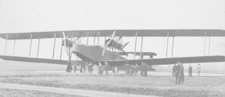
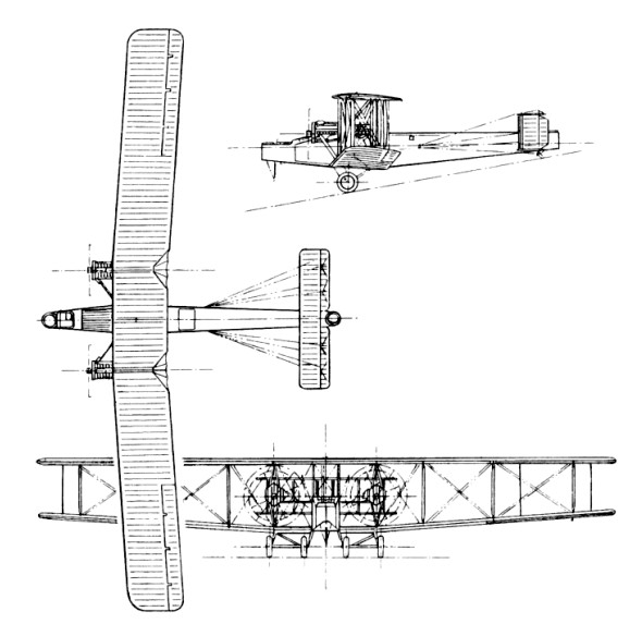
Chief designer George Volkert designed the even bigger four-engined V/1500, but the Armistice was signed before it became operational.
The V/1500 was of conventional construction. The 64ft 4in long fuselage was mainly of silver spruce, with ash cross¬ beams strengthening the bomb bay. The folding wings were also of spruce with cross bracing tie rods and, except for the plywood sheathed nose section contain¬ing the open cockpit, the aeroplane was fabric covered. The four engines installed in tandem pairs in mid gap were 12 cylinder 375 hp geared Rolls Royce Eagle VIIIs. The tractor units turned 13ft 5in ¬diameter two bladed propellers, and the pushers drove four bladers of 10ft 4in diameter.
Ordered as an experimental bomber in the summer of 1917, the V/1500 was envisaged bombing Berlin from bases in England and was designed to carry five tons of crew and disposable load. The Armistice intervened before the weather was sufficiently favourable for the three machines delivered to fly to the German capital. Power for each aircraft was provided by four 279.5kW Rolls-Royce Eagle VIIIs mounted in tandem pairs. To accelerate its introduction to RAF ser¬vice, production was ordered in January 1918, ahead of first flight, although the V/1500 took to the air for the first time on 22 May 1918, only nine months after definitive design had begun. The first prototype did crash in April that year.
At 126 ft it had the longest wingspan of any bomber the RAF would operate, but the type was too late to see service before the war ended. Nevertheless, with an endurance of 17hr it was ideally suited to long range flights, and its four engines, mounted between the upper and lower mainplanes as tractor/pusher pairs, gave it at least some measure of redundancy.
In October 1918, the Independent Force received its first bombers, each planned to drop 7,500 lb of bombs on the German capital. A Flight was formed at Bircham Newton and received its three machines early in November, just prior to the end of hostilities.
255 aircraft were ordered, but only three were operational with No.166 Squadron at the time of World War l’s end, and only about 32 were completed by the parent company, Beardmore in Scotland and Harland and Wolff in Northern Ireland. The first long flight of a V/1500 was from England to India in 1919, which included one stretch of 1,285km over water and another non-stop stage of 1,610km from Cairo to Baghdad. Flown to India by Lt. ‘Jock’ Halley, DFC, AFC, the smallest pilot in the RAF in charge of the biggest aeroplane in the world. With him went Brig.-General McEwan.
In spite of fears that it might not get over the Pathan Hills with a bomb load, Halley bombed Kabul, blowing out the walls of the Emir’s Zenana.
Only three squadrons (Nos 166, 167 and 274) ever received the type, which made some long-distance flights including the bombing of Kabul in 1919 from bases in India. The type disappeared from service in the early 1920s when it was appreciated that the smaller Vimy could undertake the same basic role at lower manpower and operating costs.