Hybrid Air Vehicles HAV-304 Airlander 10

The Hybrid Air Vehicles HAV 304 Airlander 10 is a hybrid airship made by Hybrid Air Vehicles in the UK. It was originally built for the US Army’s Long Endurance Multi-intelligence Vehicle (LEMV) project.

Following the successful demonstration of the HAV-3 small-scale demonstrator, and with Northrop Grumman as the prime bidder, the hybrid airship concept was accepted for the US Long Endurance Multi-intelligence Vehicle (LEMV) project, in preference to the Lockheed Martin P-791 also submitted.

Requirements included the capability to operate at 6 km (20,000 feet) above mean sea level, a 3000 km (2,000 mile) radius of action, and a 21-day on-station availability, provide up to 16 kilowatts of electrical power for payload, be runway independent and carry several different sensors at the same time. According to the U.S. Army, the LEMV was to have been a recoverable and reusable multi-mission platform. It could be forward located to support extended geostationary operations from austere locations and capable of beyond-line-of-sight command and control. Northrop said the LEMV could be used as a cargo aircraft, claiming that it had enough buoyancy to haul seven tons of cargo 2,400 miles at 30 miles per hour.

The HAV 304 was selected by the United States Army for its LEMV programme in which Northrop Grumman was to have been the prime contractor.

The agreement to develop the project was signed on June 14, 2010, between the U.S. Army Space and Missile Defense Command/Army Forces Strategic Command and Northrop Grumman. The agreement also included options for procuring two additional airships.

Northrop Grumman’s subcontractors included:
Hybrid Air Vehicles Ltd. in Cranfield, UK (HAV304 platform)
Warwick Mills in New Ipswich, USA (fabrics engineering)
ILC Dover in Kent County, USA (airship manufacturer and designer)
Textron subsidiary AAI Corp. in Hunt Valley, USA (makes the US Army’s OneSystem UAV/surveillance aircraft control & information distribution stations); and
SAIC in McLean, USA.

The developmental prototype emerged as the HAV 304, having an internal capacity of 38,000 cubic metres. This compares mid-20th Century airships such as the German Hindenburg-class airships which were 245 m (803 ft 10 in) long.

The airship was a hybrid aircraft and uses aerodynamic lift like a conventional aeroplane to take off before using helium to keep it in the sky once it is airborne. Engines on board are then used to move while it monitors events on the ground. The LEMV’s skin—a blend of Vectran, Kevlar, and Mylar—would have been able to cope with a “reasonable amount of small arms fire.” Northrop estimated that the biggest threat to the craft was weather, where high winds or thunderstorms could buffet the craft.

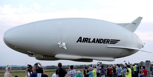
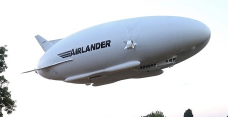
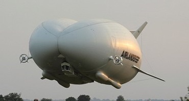
The Airlander, made by British company Hybrid Air Vehicles, has four engines and no internal structure. It maintains its shape thanks to the pressure of the 38,000 cubic meters of helium inside its hull, which is made from ultralight carbon fiber. Together with the aerodynamic shape of its hull, the lighter-than-air helium gas provides most of the lift. The aircraft’s odd shape has led some observers to describe it as a “flying bum.”

The project cost between $154 million and $517 million, dependent on all options. The cost included the design, development, and testing of the airship system within an 18-month time period, followed by transportation to Afghanistan for military assessment.

The timeline for LEMV was an 18-month schedule starting in June 2010 that included vehicle inflation at about month 10. Additional operational characterization would have occurred at Yuma Proving Ground, Arizona, in month 16.

The overall concept struggled with constant time delays and technological challenges. In October 2011 Flight International reported that the LEMV was scheduled to make its first flight in November 2011. According to media reports the LEMV was then set up for its first flight in early June 2012. However, unspecified problems delayed the flight even further. The first flight of the LEMV took place on August 7, 2012 over Joint Base McGuire-Dix-Lakehurst, New Jersey. The flight lasted for 90 minutes and was performed with a crew on board. The first flight primary objective was to perform a safe launch and recovery with a secondary objective to verify the flight control system operation. Additional first flight objectives included airworthiness testing and demonstration, and system level performance verification. All objectives were met during the first flight. That put the combat deployment of the LEMV to Afghanistan in early 2013. However, two months after the test flight, the Army said it had concerns about sending the airship abroad. These included safety, transportation to the theatre of operations, and the timeline of deployment.

The Army was slated to demonstrate the first LEMV in Afghanistan 18 months after June 2010, with proposed plans to build five others following mission completion.

On 7 August 2012 the first test flight of an LEMV was completed at Joint Base McGuire–Dix–Lakehurst, New Jersey. The vehicle tested was one of three planned for the US Army.

The US Army cancelled the LEMV project for cost reasons in February 2013. HAV bought back the airship in September 2013 for $301,000. The cameras, sensors, and communications equipment were removed and the helium was drained before the sale. In 2014—named Airlander—it was reassembled at RAF Cardington in England and re-designated the Airlander 10, to be test-flown in 2016. Hybrid Air Vehicles then managed to raise over 3.4 million pounds ($4.4 million) through two crowd funding campaigns. It also received a grant from the European Union and funding from the U.K. government. The first flight took place on 17 August 2016.

in Cardington Hangar on March 21, 2016

Gallery

HAV 304 design
Length: 91 m (298 ft 7 in)
Width: 34 m (111 ft 7 in)
Height: 26 m (85 ft 4 in)
Envelope: 38,000 cubic metres
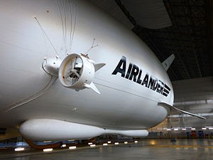
Engines: four x 350 hp, 4 litre supercharged V8 diesel

Airlander 10
Capacity: 10,000 kg (22,050 lb)
Length: 92 m (301 ft 10 in)
Wingspan: 43.5 m (142 ft 9 in)
Height: 26 m (85 ft 4 in)
Volume: 38,000 m3 (1,300,000 cu ft)
Gross weight: 20,000 kg (44,092 lb)
Powerplant: 4 × 4 litre V8 turbocharged diesel engines, 242 kW (325 hp) each
Cruising speed: 148 km/h (92 mph; 80 kn)
Endurance: 5 days manned
Service ceiling: 6,100 m (20,013 ft)
Loiter speed 20 knots (37 km/h)

Hummingbird Flying Platform

The creator of the “Hummingbird”, Rafi Yoeli of Isreal considered this machine to be a safe and truly simple-to-operate personal Vertical Take Off & Landing vehicle. It was inspired by an original 1950’s idea from the Hiller Company. The design was based on the use of a ducted fan, powered by four small internal combustion engines. The operator, standing on top, controled the vehicle by merely shifting his or her weight. A ballistically deployed emergency parachute unit was available as an optional extra.

Engines: 4 x Hirth F33-15A
Width/Diameter: 2.2 m (7.2 ft)
Height 1.9 m (4.2 ft)
Empty Weight: 145 kg (320 lbs)
Max. Gross Weight: 260 kg (572 lbs)
Fuel Capacity: 19 liters (4.8 gal)
Electric Start By Ground Assistance
Max. Speed: 40 knots
Max. Hover Height: 5000 feet
Endurance: 30 minutes

Horton Bomber Project

In February 1945 a committee under Professor Bock with representatives from Junkers, Messerschmitt and Horten, deliberated over the optimum design for a 4 jet engined bomber. Designs by Junkers (Ju 287. A swept forward tailed aircraft), Messerschmitt (Project 1107 as swept back tailed aircraft), and Horten (swept back tailless) were considered, and a joint report issued giving the committee’s opinion on the best estimate for relative performance. Junkers published the report.
The specification to be noted was for 900 kph at 10 km height and a range of 3,000 km using four H 11 jets. According to Horten the committee decided that his machine, given the same top speed as the others would have more range and less landing speed. (125 kph against the 175 kph for the others.) Alternatively he could carry 8 tons (metric) of bombs against the 4 by his competitors for the same range.
The dimensions of the aircraft were roughly as follows:

Horten said the agreed CDo for this aircraft was 0.0078 excluding Mach number correction.
In the structural design he reckoned to save 6% of the all up weight (spar and rib weight) compared with the conventional type. He thought the committee a bit unfair because they insisted on increasing his estimate of structure weight by about a ton.
All the above figures were remembered by Horton, who used them as a rough illustration. They are not accurate.

H.M. Balloon Factory R101

The British Government formulated plans for the construction of two new airships, the R100 to be built by private enterprise and the R101 to be constructed by the Government Airship Works at Cardington.

H.M. Balloon Factory R101 Article

R101 G-FAAW, powered by 650 hp Beardmore Diesel engines, was launched and moored to its mast for the first time on 12 October 1929.

Both airships had their maiden flights in 1929 with R100 being the more successful of the two to the extent that R101 was returned to the Cardington hangar for extensive modification including the insertion of another section into the ship to accommodate an additional gas cell in order to increase her lifting capacity. This added another 55 feet to the length of the ship and further delayed her flight trials.

In the meantime R100 completed a successful trial flight to Canada and back before the modified R101 had begun its trials following the modifications.

Over Bedford on its first flight

In spite of reservations, held by many technical personnel, as to the airworthiness of the modified ship, pressure brought to bear by Air Ministry Officials and the Secretary of State for Air saw the untried R101 hastily prepared for the inaugural flight to India where a mooring mast and facilities had already been prepared at Karachi.

Upon the successful completion of this flight to India and back hinged the approval of the British Government for an airship service linking the outposts of Empire including a future service to Australia and New Zealand.
Sadly, political jealousies between the Government backed faction supporting the R101 and the private enterprise airship, plus the insistence of Lord Thomson, Secretary of State for Air that the India Flight begin without delay saw the R101 lift off from Cardington on 4 October 1930 without having completed its speed trials and with a Certificate of Airworthiness issued without an inspector’s report.
R101’s departure was into overcast, wet and stormy weather. Over France worsening conditions were encountered which highlighted the airship’s deficiencies in performance and construction to the extent it became almost impossible to control.
Shortly after 2 am on 5 October, almost uncontrollable, the ship made contact with the ground, burst into flames, killing all but six of the 54 persons on board. Among those killed was the Secretary of State for Air on whose insistence the airship began its ill-fated flight long before its airworthiness had been proven.
The loss of the R101 heralded the end of the British dream for an airship service linking the outposts of Empire.

Gallery

H.M. Balloon Factory No.23 / Beardmore No. 24 / Armstrong Whitworth No. 25 / Vickers R.26 / Beardmore R.27 / HMA R29

When His Majesty’s Airship No. 9 (HMA No.9) was delivered in the clos¬ing months of 1916 it was almost obso¬lete as a result of the lengthy political vicissitudes that had bedevilled its production. It served a useful purpose, however, it had become the basic pat¬tern on which the four rigid airships for the Admiralty were later to be based. The first of these ‘23’ class airships, HMA No. 23, was subsequently deli¬vered from Vickers Limited, Barrow¬-in-Furness, to Pulham on 15 Septem¬ber 1917. Design work had started in June of the previous year, the first flight being planned for that autumn, but consider¬able redesign had to be carried out when the original specification re¬sulted in a vessel that was something like 3493 kg (7,700 lb) too heavy, the greater part of this excess being attri¬butable to the choice of engines.
The first trial flight of No. 23, four days after delivery, turned out to be something of an anticlimax, for it was clear that she too was at least obsoles¬cent, as might be expected from the original design source, and her mod¬ern counterparts had a lifting capacity some nine times greater than that of which she was capable. It is hardly surprising, therefore, that the planned total of 10 airships of this type was final¬ly cut back to six, while No. 23 was relegated to training duties. The other units of the class were HMA No. 24 (Beardmore), HMA No. 25 (Armstrong Whitworth), HMA R26 (Vickers), HMA R27 (Beardmore) and HMA R29 (Arm¬strong Whitworth), the last pair being of the improved ‘23X’ class without an exterior keel. No. 26 was the first to receive the ‘R’ prefix for rigid airships.
Mindful that in the mid-months of 1918 there was a possibility of aerial confrontations between airships of the opposing nations, experiments were carried out with Sopwith Camel air¬craft suspended beneath the envelope of No. 23; the plan in the event of an attack was for the two fighters to be released to defend the mother vessel. There was no provision at the time for the aircraft to be reclaimed.
In the spring of 1919 No. 23 was strengthened for tests at a mooring mast, but before they could be carried out she was broken up in September.

HMA No. 23
Type: naval training airship.
Powerplant: four l86.4-kW (250-hp) Rolls-Royce Eagle III 12-cylinder water-cooled piston engines.
Maximum speed 84 kph (52 mph)
Service ceiling 914 m (3,000 ft)
Range 3219 km (2,000 miles)
Useful lift 6000 kg (13,228 lb) including four 45-kg (100-lb) bombs
Diameter 16.15 m (53 ft 0 in)
Length 163.07 m (535 ft 0 in)
Volume 26674.4 cu.m (942,000 cu ft)
Armament: provision for 7.7-mm (0.303-in) Lewis gun on free mounting above forward portion of hull, plus bombs.

H.M. Balloon Factory No.9 / Vickers R.9

Plans to build a second rigid airship to follow the unsuccessful HMA No. 1 (His Majesty’s Airship No. 1) Mayfly were agreed by the Committee for Imperial Defence in early 1913, and that Vickers should be asked to design an improved class of ship incorporating all that was then known about the Zeppelins. Vickers’ airship design department had been disbanded following the failure of the Mayfly, consequently a new department was formed when the original design team was reassembled with H. B. Pratt recruited as chief designer. Pratt had been working at Vickers while the Mayfly was being constructed and had predicted that it was not structurally sound and subsequently left the company. Pratt in turn hired Barnes Wallis, whom he had met while both were working for the shipbuilding firm of J. Samuel White, as his assistant. The initial order for the new ship was placed on 10 June 1913, with the final plans being agreed at the end of the year, and a formal contract was signed in March 1914.

The initial specification called for an airship with a disposable lift of 5 tons (5080 kg) capable of flying at 45 mph (72 km/h) and maintaining an altitude of 2,000 ft (610 m) for 30 minutes; however, the required load was later reduced to 3.1 tons (3150 kg). The hull was cylindrical for most of its length and was constructed from 17-sided transverse frames with a triangular section keel underneath. Two gondolas were suspended from the keel, the forward one containing the control compartment and two of the engines, the aft containing an emergency control station and the remaining pair of engines. In addition there was a radio cabin and a mess space for the crew within the keel structure, which also contained the fuel and ballast tanks. Propulsion was provided by four 180 hp (130 kW) Wolseley engines, mounted in pairs in the gondolas. Like Mayfly, it was designed with watertight cars so that it could be operated from water. The design was based in part on French plans of Z IV which had landed in France on 3 April 1913 following an accidental incursion into French airspace, permitting a thorough examination.

Construction was delayed by a number of circumstances. Difficulties were encountered with the fabrication of the duralumin girders for the transverse frames, and there were many changes to the design, including strengthening the hull so that it could be handled safely by inexperienced crews, and replacing the original drive arrangement of paired propellers mounted on the sides of the hull with swivelling propellers mounted on the gondolas (as used on contemporary British Army dirigibles).

The construction shed at the Cavendish Dock at Barrow was too small for the new design so a new hangar was built at Walney Island, off the west of Barrow. The new shed was 540 ft (160 m) long, 150 ft (46 m) wide and 98 ft (30 m) high, and had a 6 in (15 cm)-thick concrete floor with handling rails embedded into it which extended 450 ft (140 m) into the adjacent field. As a safety measure the shed had eight fire extinguishing jets fed by a dedicated reservoir. A gasbag factory employing 100 staff was also set up beside the shed.

When World War I broke out on 4 August 1914 No.9r was nearly ready for erection, and despite competing demands for materials and manpower for other projects, construction continued during the first months of the war. However, there was a feeling that the project was no longer favoured by the Admiralty: Winston Churchill, then First Lord of the Admiralty was known to be unenthusiastic about airships, and on 12 March 1915 he cancelled the order for the ship. The reasons given for this decision were that it was expected that the war would be finished in 1915, and that the vessel would not be operational by then and thus was a waste of valuable resources.

On 19 June 1915, after Churchill had been replaced as First Lord by Arthur Balfour, a conference was held at the Admiralty to consider all airship development. At that time the non-rigid airship programme was proving to be successful, and at this meeting it was agreed to expand the non-rigid programme and also to resume construction of HMA No.9. However, resumption of work was delayed by the necessity to retrieve Pratt and Wallis who had enlisted in the Army when construction was cancelled. Final erection of the ship began in the autumn of that year, but there were delays in obtaining flax from Ireland to make nets for the gasbags following the Easter Rising, and the ship was not completed until 28 June 1916.

On 16 November 1916, No. 9r left its shed and was moored outside for tests of the fittings and engines, the first test flight taking place on 27 November 1916. This was the first time a British rigid airship had flown; however, it was unable to lift the contract weight of 3.1 tons. It was therefore lightened by the removal of both rear engines, replacing them with a single engine that had been salvaged from the Zeppelin L 33 which had made a forced landing in Little Wigborough, Essex, on 24 September 1916. New, lighter, gasbags were also fitted. These modifications increased the disposable lift to 3.8 tons (3861 kg), and it was accepted by the Navy in April 1917.

It served a useful purpose, however, it had become the basic pat¬tern on which the four rigid airships for the Admiralty were later to be based. The first of these ‘23’ class airships, HMA No. 23, was subsequently deli¬vered from Vickers Limited, Barrow¬-in-Furness, to Pulham on 15 Septem¬ber 1917.

No.9r was then sent to the RNAS airship station at Howden in the East Riding of Yorkshire where it spent most of the time being used for experimental mooring and handling tests. From 17 October 1917 to June 1918 it was stationed at RNAS Pulham in Norfolk where it was finally dismantled due to demand for shed space to allow construction of newer airships, having spent 198 hours and 16 minutes in the air, of which some 33 hours were at a mooring mast. Although unable to compete against contemporary Zeppelins, No.9r provided valuable experience of handling a rigid airship and the use of mooring masts, which would evolve into a unique method of mooring airships.

Engines: 4 × Wolseley, 180 hp (130 kW) each
Volume: 846,000 cu ft (24,000 m3)
Length: 526 ft 0 in (160.32 m)
Width: 53 ft 0 in (16.15 m)
Useful lift: 8,500 lb (3,900 kg)
Maximum speed: 43 mph (69 km/h, 37 kn)

Heinkl He 277

In an effort to overcome the problems being experienced with the coupled DB 606 engines of the He 177, Heinkel suggested in 1940 that four separate DB 603s should be substituted. Although the Reichsluftfahrtsinisterium rejected the plan, work continued unofficially under the designation He 177B and the design was resurrected in response to Hitler’s May 1943 demand for a heavy bomber to facilitate effective strikes on London. Converted from an He 177A-3/R2 airframe, with four DB 603A engines, the first Heinkel He 277 prototype flew at Vienna-Schwechat in the closing months of 1943, followed by the second aircraft on 28 February 1944. Directional instability resulted in the fitting of a twin fin and rudder tail unit to the third prototype. Eight 1305kW DB 603A-powered He 277B-5/R2 production models were completed before the priority given to fighter production in July 1944 brought the programme to an end.

Heinkl He 274 / S.N.C.A.C AAS 1

A four engine bomber, the Heinkel He 274 was the detail design responsibility of Societe Anonyme des Usines Farman’s Suresnes factory in occupied France. Fitted with a pressurised cabin in the nose, the aircraft was powered by four 1305kW Daimler-Benz DB 603A-2 engines and featured a lengthened version of the He 177A-3 fuselage, with a new high-aspect-ratio wing and twin fins and rudders.

Two prototypes were ordered in May 1943, together with four He 274A-0 pre-production examples, which were to have 1417kW DB 603G engines. Despite an unsuccessful German attempt to destroy the almost-complete first prototype when they retreated from Paris in July 1944, the aircraft was finished by the French after the liberation. The first flight was from Orleans-Bricy on 30 December 1945 as the AAS 01 A.

Two prototypes were built in France by the S.N.C.A.C.

It was used later to test-fly models of such aircraft as the Aerocentre NC 270 and the Sud-Ouest SO 4000.

M.1 glider (F-WFDJ) on Heinkel He.274 V-1

He 274
Engines: 4 x Daimler-Benz DB-603A2, 1850 hp
Propellers: metal three-bladed variable pitch
Wingspan: 44,20 m
Length: 23,80 m
Height: 5,50 m
Wing area: 142,00 sq.m
Aspect ration: 13,2
Fuel: 10130 lt
Empty weight: 21300 kg
Max weight: 38000 kg
Wing loading: 267,605 kg/sm.m
Power loading: 5,135 kg/hp
Max speed: 580 km/h
Cruise speed: 180 km/h
Ceiling: 14300 m
Range: 4250 km
Endurance: 7 hours 45 min

Heinkl He 177 Grief

The first prototype was flown in November 1939. It was a heavy bomber, introducing a power plant in which four Daimler-Benz DB 601 12-cylinder inverted engines were grouped together in pairs to create the DB 606, each pair driving a single propeller.

Many prototypes were built, most of which displayed obvious shortcomings including dangerous diving characteristics, landing gear and structural weaknesses, and problems associated with the engines including persistent crankshaft torsional vibration, lubrication and propeller troubles: two prototypes broke up in the air and at least one caught fire.

Heinkel He 177 Grief Article

Four years of development preceded the first production orders for the He 177.

Following a brief period of use as an emergency transport aircraft on the Eastern Front, during which time several caught fire and so earned the nickname “Flaming Coffin”. The first squadron of nine machines was sent to Stalingrad to supply the beleaguered fortress, but of the nine machines, seven caught fire and were burnt out.

The Greif began its operational career in October 1943 on anti-convoy and U-boat cooperation duties. It took part (sub-types A-3 and A-5) in attacks on England in January 1944, known as the “Little Blitz”, but as the war progressed was used to a greater extent as a missile carrier for anti-shipping duties. As the end of the war approached fewer and fewer Greifs remained operational: shortages of fuel and trouble with the engines grounding large numbers.

Although a small number of twin-finned He 177B were built in early 1944, most of the 1,160 or so Greifs produced were A-series types, although it is doubtful whether more than about 200 became fully operational in all respects. The He 177A-0 was the pilot production model, powered by two DB 606 engines (made up of four DB 601). Armament comprised two 13 mm MG 131 in dorsal and tail positions, one 7.9mm MG 81 in the nose, two 7.9mm MG 81 in a ventral position facing aft and a 20mm MG FF cannon firing forward from a “chin” position, plus 48x70kg, ten 500kg, six 1,000kg, or two 2,500kg bombs. The He 177A-1 was similar except for defensive armament, while the He 177A-3 had two DB 610 power units (four DB 603 engines), airframe changes and was equipped to carry two Hs 293 glider missiles. The final major version, the He 177A-5, was equipped to carry three Hs 293, two Hs 294 or two PC 1400 Fritz X (armour-piercing) radio-controlled missiles.

There were 40 modified He177 in Norway, May 1945 for a one way attack to USA.

A He 177 was intended for the continuance of the Me 264 steam turbine experiments. Later proposed designs had four separate engines which would have solved many of the problems, and was built as the He 277.

Gallery

He 177 A Greif
Length: 66.929 ft / 20.4 m
Height: 20.965 ft / 6.39 m
Wingspan : 103.15 ft / 31.44 m
Wing area : 1097.928 sq.ft / 102.0 sq.m
Max take off weight : 68355.0 lb / 31000.0 kg
Weight empty : 37044.0 lb / 16800.0 kg
Max. speed : 265 kts / 490 km/h
Cruising speed : 224 kts / 415 km/h
Service ceiling : 26247 ft / 8000 m
Wing load : 62.32 lb/sq.ft / 304.0 kg/sq.m
Range : 2970 nm / 5500 km
Engine : 2 x Daimler Benz DB 610 A, 2910 hp
Crew : 4
Armament : 3x MG 81 7,92mm, 3x MG 131 13mm, 2x MG 151 20mm, 1000kg Bomb. int., 2x HS293 Missl. ext.

He-177A-5/R-2
Engines: 2 x Daimler-Benz DB 610A/B, 2200kW
Max take-off weight: 31000 kg / 68344 lb
Empty weight: 16800 kg / 37038 lb
Wingspan: 31.44 m / 103 ft 2 in
Length: 20.40 m / 66 ft 11 in
Height: 6.39 m / 21 ft 0 in
Wing area: 102.0 sq.m / 1097.92 sq ft
Ceiling: 8000 m / 26250 ft
Range: 5500 km / 3418 miles
Armament: 3 x 7.92mm machine-guns, 3 x 13mm machine-guns, 2 x 20mm cannons, 1000kg of bomb
Crew: 6