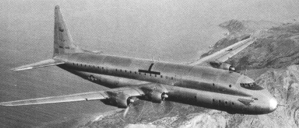
The Constitution design effort began during the war to provide an airplane capable of carrying more payload farther than could contemporary types. Pan American engineers assisted Lockheed in the initial development of the Constitution, officially sponsored by the US Navy. It was slightly larger than the DC-7, both dimensionally and in weight, and was powered by four 3,500hp (2,600kW) Pratt & Whitney Wasp Major engines. The pressurized fuselage would have provided accommodation for as many as 92 passengers on the upper deck and 76 on the lower deck.
Because of greater wartime priorities, the first of two military Model 89 Constitutions did not fly until November 9, 1946. By that time, both Pan American and the Navy had lost interest. The airplanes were delivered to the Navy in 1949 with the military model designation XR6O-1.
Later designated XR6V-1s, both Constitutions were sold by the US Navy in 1958 after less than 2,000 flying hours each. The first ended its days at Opa-locka, Florida, in the 1970s, while the second was scrapped at Las Vegas, Nevada, in 1969.
Engines: 4 x Pratt & Whitney Wasp Major, 3,500hp (2,600kW) Wingspan: 57.63m Crew: 12 Pax capacity: 168
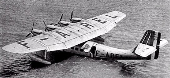
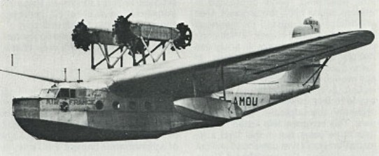
In January 1938, Air France ordered six H-246.1 aircraft in addition to the prototype, and two aircraft were about to enter service on the Marignane-Algiers route when war broke out. The French navy intended to impress all six series aircraft for maritime reconnaissance, but in the event only one was converted. This was the third series aircraft, which flew in June 1940, and then went into service with Escadrille 9.E with a modified extended glazed nose section. It was armed with four 7.5mm Darne machine-guns and 600kg of bombs.
From October 1939 to November 1942 the civil LeO boats operated the route to Algiers for Air France. After that they were seized by the Luftwaffe, converted to carry 21 troops or 14 stretcher cases, and armed with five 7.92mm MG 15 machine-guns, one in a bow turret, two in lateral positions and two more firing through windows at the rear of the flight deck. They were used on a variety of tasks, including brief operations in Finland. Post-war, two surviving LeO H-246.1s were used for a time on the Air France Marignane-Algiers route.
Designed to an official requirement of 1935, the Liore-et-Olivier LeO H-246.01 flying-boat prototype flew on 30 September 1937. A graceful parasol-wing monoplane, its metal hull incorporated a flight deck for the four-man crew and a main cabin for 26 passengers.
H-246.1 Engine: 4 x Hispano-Suiza 12Xgrs/Xhrs V-12, 537kW Max take-off weight: 15000 kg / 33070 lb Loaded weight: 9800 kg / 21605 lb Wingspan: 31.72 m / 104 ft 1 in Length: 21.17 m / 69 ft 5 in Height: 7.15 m / 23 ft 5 in Wing area: 131.0 sq.m / 1410.07 sq ft Max. speed: 330 km/h / 205 mph Ceiling: 7000 m / 22950 ft Range: 2000 km / 1243 miles
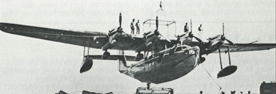
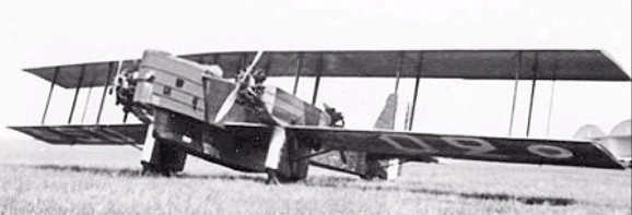
In search of a more powerful night-bomber, the Liore-et-Olivier design team developed a large four-engined machine, the Liore-et-Olivier LeO 203. This was first flown in May 1930, and was powered by four 224kW Gnome-Rhone 7Kb radials mounted in pairs on the lower wings. Soon afterwards a floatplane version was flown under the designation LeO 204. A 1931 order for 40 LeO 203s was transferred to the LeO 206, the first of which made it maiden flight in June 1932. This had a redesigned nose, a ventral balcony which housed the bomb-bay and, at the rear, a defensive gun position, and was powered by four 261kW Gnome-Rhone 7Kd radials. The LeO 206 equipped Groupe de Bombardement III/12 at Reims and then GB I/22 at Chartres. Three aircraft of the original order for 40 were completed as LeO 207 machines with a nose section similar to that of the LeO 203 and a smaller ventral balcony than that of the LeO 206. Performance was improved by the installation of Gnome-Rhone Titan Kds supercharged engines. The ability of the LeO 206 to remain aloft on only three or even two engines gave it an extended life. Nicknamed Caravelle, 29 were still in flying condition in September 1939, the majority of them stationed in Morocco.
LeO 206 Engine: 4 x Gnome-Rhone 7Kd Titan radial, 261kW Max take-off weight: 8450 kg / 18629 lb Loaded weight: 4230 kg / 9326 lb Wingspan: 24.54 m / 80 ft 6 in Length: 14.77 m / 48 ft 5 in Height: 6.28 m / 20 ft 7 in Wing area: 118 sq.m / 1270.14 sq ft Max. speed: 215 km/h / 134 mph Ceiling: 7250 m / 23800 ft Range: 2000 km / 1243 miles Armament: 6 x 7.7mm machine-guns, 1500kg of bombs
The result of prolonged design work by Benoit and his design team, the Liore-et-Olivier H-24.01 made its first flight in November 1929. A cantilever high-wing monoplane flying-boat, the H-24 had an enclosed pilot’s cockpit, cabin accommodation for 10 passengers and a distinctive tall single fin and rudder, and was powered by two 373kW Renault 12Jb V-12 engines mounted in tandem on a pylon over the hull. This single aircraft was used purely for development, making a number of test and demonstration flights before being scrapped at Antibes in 1934. Developed from the H-24 was the H-24-2, of similar configuration but powered by four Gnome-Rhone radial engines mounted in tandem pairs over the thick-section wing. The first two of 14 production aircraft for Air France were H-24-2s, and the remaining 12 were H-24-2/1 aircraft with a revised engine installation. The first H-24-2 had flown for the initial time in March 1933, and before long all the machines were employed on Air France routes linking Marseilles with Athens, Tunis and Beirut. Ten aircraft were still operational in September 1939, and were flown under Italian supervision after the German occupation of southern France in November 1942. It is understood that most were scrapped shortly afterwards. The H-24-2 and H-24-2/1 had an enclosed crew cabin with side-by-side pilots’ seats and a navigation and radio compartment; 15 passengers could be accommodated in a cabin beneath the wings, and there was a sizeable luggage and mail hold at the rear.
LeO H-24-2/1 Engines: 4 x Gnome-Rhone 7Kd Titan Major radial, 261kW Max take-off weight: 8700 kg / 19180 lb Loaded weight: 5868 kg / 12937 lb Wingspan: 28.0 m / 91 ft 10 in Length: 18.45 m / 60 ft 6 in Height: 6.33 m / 20 ft 9 in Wing area: 116.25 sq.m / 1251.30 sq ft Max. speed: 240 km/h / 149 mph Ceiling: 4500 m / 14750 ft Range: 1100 km / 684 miles
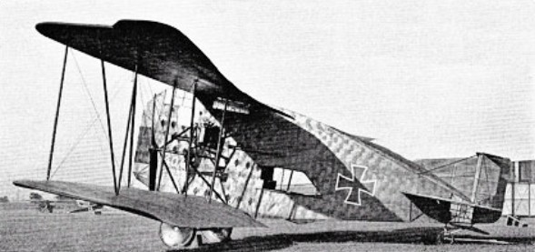
The R.II was a large four-engined bomber with the engines were buried in the fuselage and geared together to drive the single 7m Garuda propeller in the nose. The propeller was geared down to 545 rpm. Only the one was flown; a second was under construction at the war’s end.
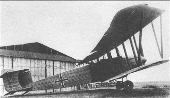
Both R.I prototypes used four 260hp Mercedes D.IVa engines, carried inside the fuselage, powering two chain-driven propellers.
The Linke-Hoffmann R.I was half covered with transparent Cellon in an attempt at partial invisibility. It achieved the opposite effect, partly because the Cellon discoloured rapidly, but mainly because it reflected the sun so strongly.
R.I serial R.8/15
The two built were R.I serial R.8/15 and the improved R.I serial R.8/16. The first was burnt out in an accident in May 1917and the second was destroyed when the pilot misjudged his height during a normal landing.
Further experimentation with unorthodox propulsion configurations would lead to the R.II.
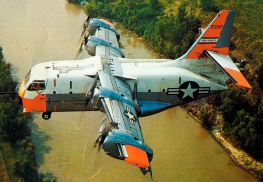
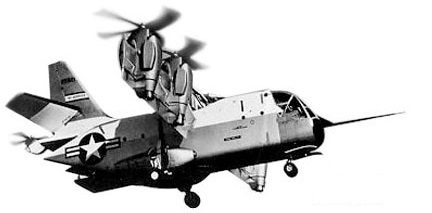
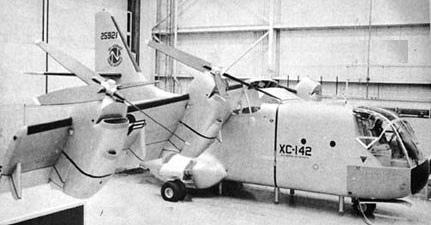
A government advisory group in 1959 recommended that a full-size V/STOL aircraft was required, with specific requirements for the Navy and Army. Previous VTOL programs had been built to illustrate a particular principle, but few of these concepts had any operational military capabilities. With the XC-142, it was decided that this system would be tested in an operational environment. It was decided that the system would fulfill requirements for all three military services. The first tri-service VTOL. In 1961, a Request for Proposal was released, and in September, the proposal from Vought-Hiller-Ryan was announced as the winner. It was also announced that the Air Force would manage the program with the cost of the program to be shared equally by each of the services. Vought Aeronautics Division of Ling-Temco-Vought was the prime contractor, with Hiller and Ryan serving as the major subcontractors. Vought subcontracted the design and fabrication of the empennage, aft section, engine nacelles, and wing to Ryan. The overall transmission system and selected components were subcontracted to Hiller, which was also responsible for the flap and aileron fabrication. The XC-142 grossed out at about 16900kg loaded with an empty weight of about 10780kg. The plane had a fuselage length just exceeding 17.7m, with a maximum height of 7.9m and a sizable wing span of 20.6m. The model carried a single tall vertical tail that provided 12sq.m of area. The wings carried large trailing double-slotted flaps the entire length of each wing and were mounted high on the fuselage. The fuselage was designed to carry significant cargo, with the cargo compartment being 9.15m in length with a 2.1m height and width. That volume equated to about 32 full-loaded troops and gear, or four tons of cargo. In addition to that capability, there was also the ability to carry 370 litres of fuel. There was also a planned capability for auxiliary tanks which would greatly add to the range.
XC-142 62-5921
Power consisted of four 3080hp General Electric T64-GE-1 engines, mounted in nacelles on the wings, which were all cross-linked together. Each drove a four-bladed 4.7m Hamilton-Standard fiberglass propeller, the tips of each practically overlapping each other. Later in the program, Hamilton Standard would provide an improved version of the propeller using the 2FF blade design, which featured a wider planform, rounded tips, and a more pronounced twist than the earlier 2EF blades. The goal of the new design was to improve aerodynamic load distribution and overcoming a static load problem. The four engines also drove a fifth propeller, a three-bladed fiberglass type, in the tail through an interconnected gear and shaft train. Therefore, power was available to turn all five propellers when one, two, or three engines were shut down. The tail propeller rotated in a horizontal plane and was declutched and braked for cruise flight. Through cross-shafting gearboxes, the rotation from each engine was brought together at the top of the fuselage. The power was then sent back to the tail rotor through a tail propeller shaft, into the tail propeller gearbox, and on to the variable pitch tail propeller. The propulsion system of the XC-142 was over powered. The plane could lose an engine on take-off and still clear a 15.25m barrier in 122m carrying a 4500kg payload. Also, with all engines operating, the plane had a rate of climb at sea level of 34.5m/s. On a hot day, even with an engine out, the XC-142 showed a climb rate of 17.8m/s. Roll control was by differential propeller pitch. Pitch control was accomplished by the eight-foot, three-bladed variable pitch tail rotor. Yaw control was provided by ailerons powered by propeller slipstream deflection, actually a second VTOL concept being employed in the XC-142. The craft main lift system in the wing was capable of rotating through 98 degrees instead of the expected straight-vertical position. The wing tilt mechanism consisted of two screw-jack actuators driven by a centrally-located hydraulic motor. The tilt was controlled by a variable rate switch on each collective lever, or by a constant rate switch. This allowed the plane to hover in a stationary mode in a tailwind condition. The trailing edge of the wings carried three-section, double-slotted flaps in three sections, with the center and outboard sections operated also as ailerons. The flaps were programmed automatically with changing wing tilt, although the pilot had an override capability. Leading edge slats were used for stall suppression, and were mounted outboard of each engine nacelle and operated automatically as a function of flap position. The vertical tail was operated as a standard rudder-and-fin set-up, which supported the slab-type unit horizontal tail assembly. A fully-powered irreversible type with artificial feel forces and powered by dual independent hydraulic systems was fitted. Dual cockpit controls, consisting of conventional rudder pedals, control sticks, and collective levers for all take-offs and landings, provided the highest technology of the system. The tail rotor was rigged to fold to the port side to reduce the storage length and protect against damage during a loading operation.
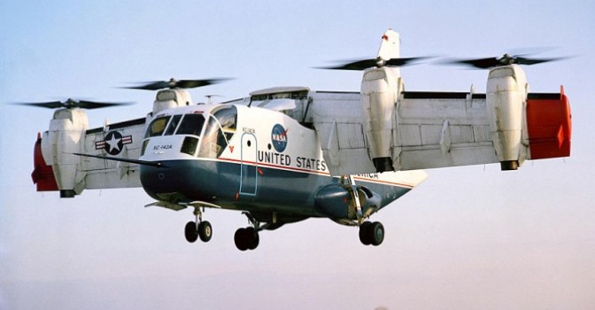
The first XC-142 was rolled out in early 1964 with its first conventional flight being made in September 1964, its first hover three months later, and the first transition from hover to horizontal flight and return on 17 January 1965. The Air Force extensively tested the XC-142’s capabilities with cargo flights, cargo, and paratrooper drops, along with desert, mountain, rescue, and carrier operations.
XC-142 62-5921
In 1966, one of the XC-142s passed operational tests to prove the model in carrier operations. In quick succession, the plane accomplished 44 short take-offs and landings, along with six vertical take-offs and landings from the USS Bennington.
The carrier trails were accomplished using the number five prototype, which was crewed by both USMC, Navy, and Army pilots. The flight regime covered VTOL operations at a variety of speeds, which occurred at wind conditions from 10 to 55km/h. A large variety of wings and flap tilt angles were used during the testing. Also, there were landings accomplished with three and six degree glide slopes. In an amazing demonstration, the plane negotiated a 360-degree turn within the width of the flight deck. That same year, one of the prototypes was also tested in an overwater pickup operation. The plane lifted a man from a life raft to determine its capability for rescue and recovery. A standard Navy horse collar sling was attached to 38m of cable and then lowered through a floor hatch just aft of the cockpit. The tests proved that there were no problems with effects of the propeller downwash or slipstream turbulence.
The program called for the building of five prototypes, 62-5921-5925, but cross-shaft problems, along with some operator errors, resulted in a number of hard landings causing damage to the complete fleet.
The most serious of the mishaps, resulting from a tail rotor driveshaft failure, caused three fatalities. The May 1967 accident took place near the Dallas, Texas, LTV plant and occurred in a heavily-wooded area where fire started after the impact. The flight plan for the ill-fated prototype included a rapid decrease in altitude from 2440m to 915m, effectively simulating a pilot rescue under combat conditions. A nose-over at low altitude followed, from which the crew could not recover. The crash aircraft was XC-142 #1 which had flown 148 times at the time of the crash. The pilots on the fatal flight were Stu Madison, Charlie Jester, and John Omvig.
Other incidents included the following:
Aircraft #2 – On October 19, 1965, this craft experienced a ground loop causing extensive damage to the wing and propeller.
Aircraft #3 – On January 4, 1966, this model made a hard landing in the vertical mode. There was significant damage to the fuselage. The wing of this plane was late mated to the Number #2 for further testing.
Aircraft #4 – On January 27, 1966, an engine turbine failure caused the overriding clutch to engage, causing extensive damage to the wing, outboard aileron, the number two nacelle, aft engine shroud, and fuselage. It was later used by NASA for further research.
Aircraft #5 – ln December of 1966, a ground accident caused major damage to the fuselage, nose, wing, and propellers. The incident was caused by pilot error who failed to activate the hydraulic system, which resulted in no brakes or nose wheel steering.
The final decision on the disposition of the aircraft occurred during the Category II Operational Suitability Program, which was conducted at the Air Force Flight Test Center. The testing consisted of 113 flights, totaling 163.9 hours, which was accomplished between July 1965 and August 1967. Three of the XC-142s also participated in a major operational test demonstration during the program, where the planes participated in demonstrations of VTOL, STOL, and movement of Jeep-mounted 106mm recoilless rifles, unloading of three-quarter ton trucks with towed 105mm Howitzers, dump trucks, and 450-kg A-22 containers. For a typical XC-142 design mission, the plane could operate with a gross weight of 16900kg, including a four-ton payload. At that weight condition, the plane could take off vertically, cruise 370km near 480km/h, hover for ten minutes, and then land. One of the limitations found in the plane, even though the overall test results were very positive, was an instability between wing angles of 35 and 80 degrees which was encountered at extremely low altitudes. There were also high side forces which resulted from yaw and weak propeller blade pitch angle controls. Another XC-142 complaint was the excessive vibration and noise in the cockpit, when coupled with an excessively high pilot workload, and which presented a considerable challenge in the cockpit. The program involved 39 different pilots flying the prototypes for a total of 420 hours.
The greatest national exposure the XC-142 received during its flight test program occurred when the #4 prototype participated in the 1967 Paris Air Show.
The only remaining XC-142, #2 62-5924 / NASA522, was on display at the Air Force Museum at Wright-Patterson Air Force Base near Dayton, Ohio.
XC-142A Crew: 2 Passengers: 24-44 Engines: 4 x General Electric T-64 turboshaft, 2095kW Wingspan: 20.6m Length: 17.8m Height: 8.0m Wing area: 49.7sq.m Empty weight: 10250kg Max speed: 667km/h Ceiling: 7620m Range with max fuel: 756km Range with max payload: 370km
The Latécoère Laté 610 Series were 1935 4-engined long-range flying boats
Laté 610: [Project] May 1935 recce flying boat for Aéronavale Laté 610 as designed, single fin, span 38 m, length 24.5 m Laté 611: enlarged recce flying boat to mod. Dec 1935 spec. Laté 611 as planned, 4 x 1000 hp HS.79.02 radials Laté 611-01: 1939, conv. under const. to 4 x 10¹⁰ hp G-R 14N4/5 Laté 611-01, G-R 14N30/31 engines substituted after trials Laté 612 diff. in having 4 x powered turrets (incl. tail turret)