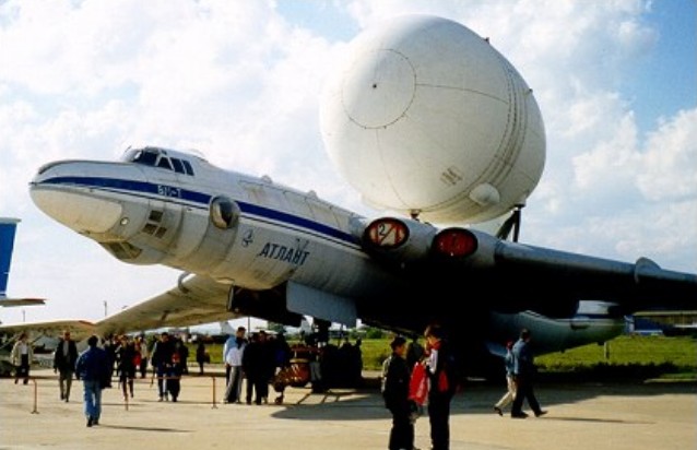
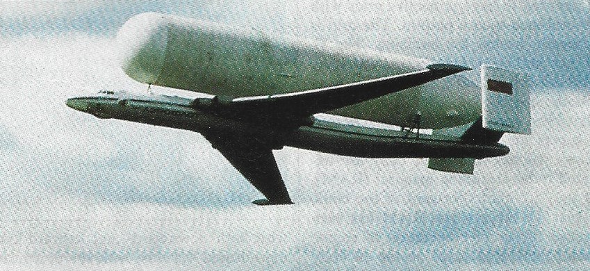
After directing CAHI (TsAGI) from 1960, Myasishchev returned to OKB No 23 in early 1978 in order to study how a 3M strategic bomber might be modified to convey large space launchers and similar payloads. In particular an aircraft was needed to transport to the Baikonur launch site four kinds of load: the nose of the Energiya launcher; the second portion of Energiya; the Energiya tank; and the Buran spacecraft, with vertical tail and engines removed. These loads typically weighed 40 tonnes and had a diameter of 8m. Myasishchev had previously calculated that such loads could be flown mounted above a modified 3M bomber. He died on 14th October 1978, the programme being continued by V Fedotov. While design went ahead, three 3M tanker aircraft were taken to SibNIA (the Siberian State Research Instiutute named for S.A.Chaplygin) and put through a detailed structural audit preparatory to grafting on a new rear fuselage and tail, and mountings for the external payload. The modified aircraft were designated 3M-T. All were rebuilt with zero-life airframes and new engines, but initially without payload attachments. One was static-tested at CAHI while the other two were completed and flown, tne first on 29th April 1981. After a brief flight-test programme they were equipped to carry pick-a-back payloads, and in Myasishchev’s honour redesignated VM-T Atlant. The first flight with a payload was made by A.Kucherenko and crew on 6th January 1982. Subsequently the two Atlant aircraft carried more than 150 payloads to Baikonur.
The most obvious modification of these aircraft was that the rear fuselage was replaced by a new structure 7m longer and with an upward tilt, carrying a completely new tail. This comprised modified tailplanes and elevators with pronounced dihedral carrying inward- sloping fins and rudders of almost perfectly rectangular shape, with increased total area and outside the turbulent wake from any of the envisaged payloads. Less obvious was the fact that, even though the maximum take-off weight was less than that for the bomber versions, the airframe was strengthened throughout.
As time between overhauls was not of great importance the original four VD-7B engines were replaced by the VD-7M. These were RD-7M-2 engines, originally built for the Tu-22 supersonic bomber with afterburners and variable nozzles, which had had the afterburner replaced by a plain jetpipe and fixed-area nozzle. Thrust was 11,000kg. These were in turn replaced by the VD-7D, rated at 10,750kg. Each aircraft was fitted with 14 attachment points above the fuselage and on lateral rear-fuselage blisters for the four different kinds of supporting structure, each being specially tailored to its payload. They were also equipped with a modified flight-control and autopilot system. The forward fuselage was furnished with work stations for a crew of six.
The aircraft were given civilian paint schemes, one being registered RF-01502 and the other being RF-01402 and fitted with a flight-refuelling probe. To support their missions the PKU-50 loading and unloading facility was constructed at spacecraft factories, including NPO Energiya at Moscow Khimki, and at the Baikonur Cosmodrome. These incorporated a giant gantry for carefully placing the payloads on the carrier aircraft. Despite the turbulent aerodynamics downstream of the external payloads, this dramatic reconstruction proved completely successful.
Max take-off weight: 136400 kg / 300712 lb Max. speed: 600 km/h / 373 mph Cruise speed: 540 km/h / 336 mph Ceiling: 9500 m / 31150 ft Range w/max.fuel: 3000 km / 1864 miles Range w/max.payload: 1500 km / 932 miles Crew: 6
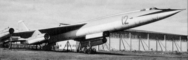
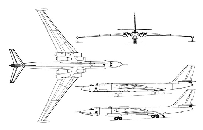
To succeed its M-4, Myasishchyev produced the M-50, codenamed ‘Bounder’ by NATO.
It was based on a very long area-ruled fuselage with two four-wheel main landing gear bogies arranged in tandem to retract into the lower fuselage. This was basically the same arrangement as that used in the M-4, as was the use of two twin-wheel stabilizers of the outrigger type that retracted aft into the wingtips. The cropped delta wing was located in the shoulder position with its leading edges swept at 500 inboard decreasing to 41030’ outboard. The tail unit was conventional for a supersonic type, with powered all-moving slab tailplane halves and a fin with a powered rudder.
The crew of three was accommodated in a pressurized nose compartment on tandem ejector seats behind a V-shaped windscreen whose contours were continued aft of the cockpit by a long dorsal spine stretching as far as the extreme tail. In the first aeroplane the four engines were located on pylons under the wing leading edges. Power was provided by four Soloviev D-15 turbo-jets of 13000kg thrust.
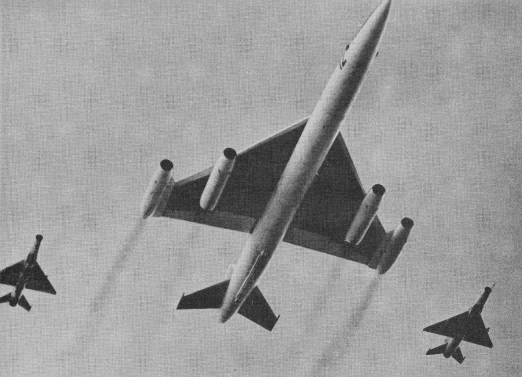
First flight dates between 1957 and 1961 have been quoted, and it is believed that a maximum speed in the order of Mach 1.8 was achieved. By the standards of the day this was a good figure, but the range of 3730 miles (6000 km) without payload was poor. It was seen at the 1961 Soviet Aviation Day display.
The last of several prototypes, generally known as the M-52, had a different powerplant arrangement: the two inboard engines remained on underwing pylons. The M-52 was powered by four Kolesov ND-7F or VD-7F turbojets, with an afterburning thrust of 18145kg. The two outboard engines remained non-afterburning units but were arranged on pylons with forward-swept leading edges projecting horizontally from the cropped tips of the delta wings. The M-50/M-52 series failed to progress past the prototype stage. The Bounder was intended to carry a weapons load of up to 20,000kg.
M.50 Engines: 2 x 14500kg Kolesov VD-7F and 2 x 12260kg VD-7 turbojets Wingspan: 37.0 m / 121 ft 5 in Length: 57.0 m / 187 ft 0 in Height: 12.0 m / 39 ft 4 in Wing area: 282.0 sq.m / 3035.42 sq ft Max take-off weight: 200000 kg / 440927 lb Empty weight: 74500 kg / 164245 lb Max. speed: 1053 kts / 1950 km/h / 1212 mph Cruise speed: 1500 km/h / 932 mph Ceiling: 20000 m / 65600 ft Range w/max.fuel: 6000 km / 3728 miles Armament: 20000kg of bombs and missiles Crew: 2
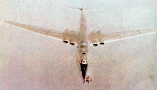
In 1951 V. M. Myasishchyev was directly ordered by Stalin to build a jet bomber to fly long range strategic missions. The Myasishchyev M-4 (often called the Mya 4, and called Molot, meaning hammer, by the Soviets, and given the codename ‘Bison’ by NATO) proved successful.
A mid-wing cantilever monoplane with a deep section swept wing, the M-4 has a tail unit with all-swept surfaces, and retractable landing gear comprising two main units in tandem on the fuselage centreline, each with a four-wheel bogie, plus twin-wheel outrigger balancing units which retract into the wingtips. The circular-section fuselage incorporates a pressurised nose compartment and tail turret for the crew, and a large internal weapons bay in the lower fuselage between the main landing gear units. The powerplant comprises four turbojets buried in the wing roots, these being initially Mikulin AM-3Ds each of 8700kg thrust.
Following its maiden flight in late 1953, a single example of this large aircraft took part in the 1954 May Day parade fly past over Moscow, its size being gauged from the escorting MiG fighters. It was expected to appear in large numbers, but little was heard of it for years. In fact a useful run of about 150 had been delivered, at first being used as free fall bombers (Bison A), reaching regiments of the DA (Long Range Aviation) in 1956. Altogether about 200 were built. By 1959 the Mya-4 bombers were being fitted with more powerful engines, and their role changed from bomber to long-range over-sea reconnaissance, ECM and, in some cases, flight-refuelling tanker. Many were given different noses as ‘Bison B’ and ‘Bison C’ for maritime reconnaissance purposes. All aircraft were given large fixed FR probes, the rear turrets were removed and a vast amount of special reconnaissance equipment fitted, with from five to 17 aerials visible all over the aircraft.
In the Bison C- sub-type a large search radar fills the entire nose, lengthening the nose by about 6 ft and changing its shape. Since 1967 these now obsolescent aircraft have been frequently encountered on probing missions far over the Arctic, Atlantic, Pacific and elsewhere, at both high and very low levels, the C-model having been seen most frequently.
Bison C
In 1983 it was estimated that 43 remained in active service in the original role. Supporting them are another 30 rebuilt as inflight-refuelling tankers, with many modifications including a large hose drum unit in the rear of the weapon bay. ‘Bison B’ was a long range maritime reconnaissance version, possibly re-built from the original bomber, with a ‘solid’ nose housing a mapping and ship targeting radar with the refuelling probe above. Numerous other reconnaissance systems were installed. ‘Bison C was an improved maritime reconnaissance version with an even larger surveillance radar (NATO name ‘Puff Ball’) in a more pointed nose swollen at the sides and with the refuelling probe at the tip. These flew surveillance and electronic missions for the AV MF (Naval Air Force).
In all about 150 were built.
About 40 tanker/transport versions of the M-4 were estimated to remain in service in 1992. These were to be replaced by II-78 ‘Midas’ tankers.
M-4 / 3M Engines: 4 x VD-7, 107.8kN Max take-off weight: 202000 kg / 445336 lb Empty weight: 74430 kg / 164091 lb Wingspan: 50.53 m / 165 ft 9 in Length: 51.70 m / 169 ft 7 in Wing area: 340.0 sq.m / 3659.73 sq ft Max. speed: 940 km/h / 584 mph Ceiling: 12150 m / 39850 ft Range: 11850 km / 7363 miles Endurance: 15 hr Armament: 6 x 23mm cannons, 24000kg of bombs and missiles Crew: 8
Bison A Type: heavy bomber Engines: 4 x Mikulin AM-3D single-shaft turbojets, 19,180 lb (8700 kg). Estimated, span 165 ft 7½ in (50.48 m) Estimated Length 154 ft 10 in (47.2 m) Estimated height 46 ft (14.1 m) Estimated empty 154,000 lb (70,000 kg) Estimated maximum loaded 352,740 lb (160,000 kg) Estimated Max speed 560 mph (900 km/h) Estimated Range 6,835 miles (11,000 km) with 9,920 lb (4500 kg) of bombs or electronic equipment. Service ceiling 42,650 ft (13,000 m) Armament: ten 23 mm NR-23 cannon in manned turret in tail and four remotely controlled turrets above and below front and rear fuselage (two guns in each turret); internal bomb bays in tandem for at least 22,050 lb (10000 kg) stores.
Bison B Type: strategic reconnissance and ECM Engines: 4 x D-15, 28,660 lb (13,000 kg) Estimated empty 176,400 lb (80,000 kg) Estimated maximum loaded 375,000 lb (170,000 kg) Estimated Max speed 560 mph (900 km/h) Estimated Range 6,835 miles (11,000 km) with 9,920 lb (4500 kg) of bombs or electronic equipment. Service ceiling 49,200 ft (15,000 m) Armament: six 23 mm cannon in two forward turrets and tail turret, internal bay for at least 10,000 1b (4500 kg) stores. In many versions a single 23 mm gun is fixed on the right side of the nose, firing ahead.
Bison C Type: multi-role reconnaissance bomber Engines: 4 x D-15, 28,660 lb (13,000 kg) Estimated empty 176,400 lb (80,000 kg) Estimated maximum loaded 375,000 lb (170,000 kg) Estimated Max speed 560 mph (900 km/h) Estimated Range 6,835 miles (11,000 km) with 9,920 lb (4500 kg) of bombs or electronic equipment. Service ceiling 49,200 ft (15,000 m) Armament: six 23 mm cannon in two forward turrets and tail turret, internal bay for at least 10,000 1b (4500 kg) stores. In many versions a single 23 mm gun is fixed on the right side of the nose, firing ahead.
M-4 Bison E Type: six seat strategic bomber Engines: 4 x 9500 kg (20,943 lb) thrust Mikulin RD 3M turbojets Max speed at high alt: 1000 km/h (621 mph) Service ceiling at normal loaded wt: 17000 m (55,775 ft) MTOW Service ceiling: 13000 m (42,650 ft) Range 10700 km (6,650 miles) Empty wt: 70000 kg (154,321 lb) Normal loaded wt: 160000 kg (352,734 lb) MTOW: 210000 kg (462,963 lb) Wing span: 50.48 m (165 ft 7.5 in) Length (no probe): 47.20 m (154 ft 10 in) Height: 14.24 m (46 ft 0 in) Wing area: 309.0 sq.m (3,326.2 sq ft) Armament: (as built) 10x 23 mm cannon in five power turrets; internal bomb bay for 15000 kg (33,068 lb) bombload.
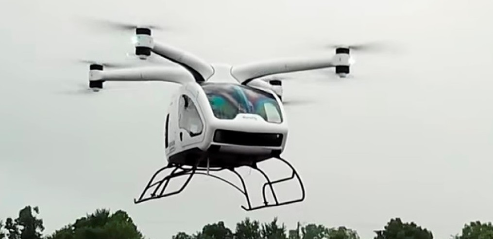
On 30 April 2018 the Moog Surefly flew its first flight. The configuration of the Surefly is four arms with the counterrotating propellers are mounted above the aircraft instead of close to the ground.
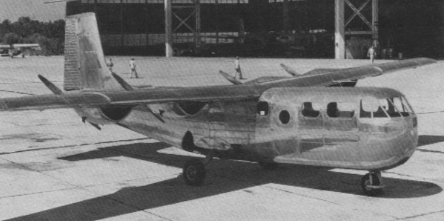
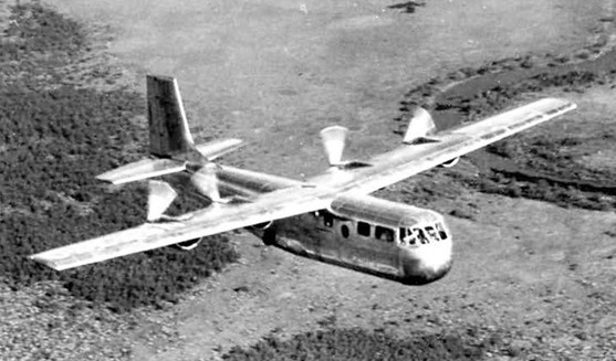
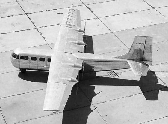
The 1949 Monsted Vincent Starflight featured four 85 horsepower Continental C85s driving two position pusher props. It had room for a pilot, four passengers. Gross weight was 5,000 pounds with a 130 knot cruise and 1,050 nautical mile range. It was built in New Orleans.
The all-aluminum Monsted–Vincent MV-1 Starflight pusher airplane was the only four-engined aircraft ever to be built in Louisiana. It was to be an executive/business aircraft, designed by former Lockheed designer Art Turner “to give businessmen the same dependability and flying range that airlines give to their passengers.”
The only Starflight flew for the first time in October 1948. Despite having four engines, the Starflight could only carry 5 passengers and the pilot. It had a range of 1,200 miles at 145 mph, making it a terrible aircraft for businessmen who are looking for speedy travel.
The only copy ended up at the Wedell Williams Memorial Aviation Museum in Patterson, Louisiana, USA, where, in 1992, it was heavily damaged by Hurricane Andrew. The wreck was moved to a storage hangar, where in 2005, it was destroyed by Hurricane Rita.
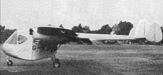
In August 1947 Miles flew the M.71 Merchantman with four 186kW de Havilland Gipsy Queen 30 engines and a modified Marathon wing. Configuration was similar to that of the Aerovan, but the aircraft was of metal construction. The Merchantman could carry 2268kg of freight or 20 passengers over 1367km. The design was unable to proceed because of the firm’s collapse.
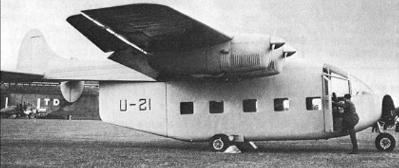
The Miles M.68 Boxcar, flown on 22 August 1947, had four 75kW Blackburn Cirrus Minor II engines and was basically of Aerovan layout, except that the centre section of the fuselage was designed to mount a detachable container 1.37m square and 3.05m long, the idea being that freight containers could be pre-loaded and the aircraft could be flown with or without the container attached.
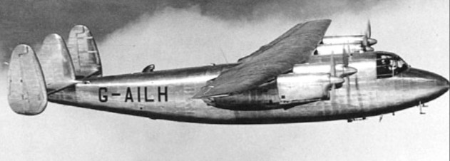
Flown in 1946 with Gipsy Queen 71 engines, the Marathon was the winner in a competitive bid to Air Ministry Specification 18/44, and the Ministry ordered three prototypes for BOAC.
The Ministry of Aircraft Production, gave orders and counter orders throughout the pre-production stages, but when the prototype flew test pilots soon found it was a very pleasant aircraft to handle. Loss of the prototype in a fatal crash during trials at Boscombe Down was attributed to pilot error. The second prototype flew in February 1947, but before a production contract could be signed the Miles company suffered financial collapse and its aircraft assets were eventually acquired by Handley Page. The company became Handley Page (Reading) Ltd. and the 18 passenger M.60 Marathon was redesignated Handley Page H.P.R.1 Marathon I.
A production order for 50 was placed, 30 for BEA and 20 for BOAC’s associated companies, but the BEA order was reduced to 25 and later seven, then cancelled completely, and 28 of the Marathons were modified for use by the RAF as navigation trainers as the Marathon T.Mk II, serving for six years before being replaced by Vickers Varsities.
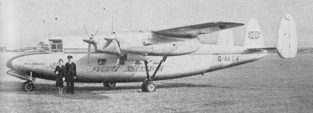
Handley Page built only 40. The remaining aircraft operated in a number of overseas countries including West Germany, Jordan, Nigeria, Canada, Japan and Burma.
Derby Aviation Marathon circa 1958
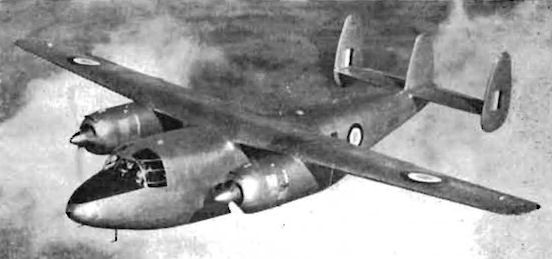
Some were used experimentally, including use as engine test-beds, one equipped with a pair of Mamba turboprops, designated M.69 Marathon II. Flown by the Handley Page company, initially with two 753kW Armstrong Siddeley Mamba turboprop engines, it was later used to test two Alvis Leonides Major radial engines.
First flown on 15th March 1955, the Leonides Major-powered Marathon was at the Handley Page (Reading) works at Woodley. It was to act as a general flying test-bed for the Leonides Major, but in particular for the construction of the engine at Handley. The Marathon itself, serial VX231, was originally G-AHXU, with two Armstrong Siddeley Mambas in place of the four Gipsy Queen inlines.
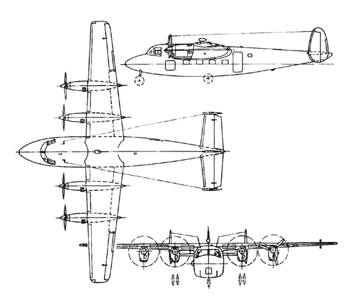
The fuselage is deep and flat-bottomed with a rounded nose, stepped cockpit, and square cabin windows. The underside of the fuselage has a marked upsweep. The wing is equi-tapered with square-cut tips and the engines are housed in a circular section of nacelles. There are prominent underwing bulges on the trailing edge outboard of the nacelles. The tail unit has triple oval fins. Main undercarriage legs retract forwards into the nacelles, and the nosewheel also folds forwards.
The last survivors were scrapped around the mid-1960s.
M.60 Marathon Engines: 4 x de Havilland Gipsy Queen 71, 246kW Wingspan: 19.81 m / 64 ft 12 in Length: 15.93 m / 52 ft 3 in Height: 4.27 m / 14 ft 0 in Wing area: 46.45 sq.m / 499.98 sq ft Max take-off weight: 7484 kg / 16499 lb Empty weight: 5198 kg / 11460 lb Max. speed: 322 km/h / 200 mph Ceiling: 5030 m / 16500 ft Range: 1368 km / 850 miles
HPR.5 Engines: two Leonides Major Wingspan: 65 ft Length: 52 ft 1 in Height: 14 ft 1 in
The origins of the V-12 / Mi-12 (NATO reporting name Homer) lie with a 1965 Soviet air force requirement for a heavy-lift helicopter able to carry major missile components. These would be brought into remote missile site areas by fixed-wing aircraft, notably the Antonov An-22, and then lifted from the airfield to the launch site by the new helicopter.
There also existed a civil requirement for such a machine, principally for use in developing Siberia which is resources-rich but communications-poor. The military specification, calling for a tandem-rotor configuration using dynamic system components from existing helicopters, and the V-12 has the same basic hold dimensions as the An-22: 4.4m by 4.4m, with length only 4.85m less than that of the An-22 at 28.15m.
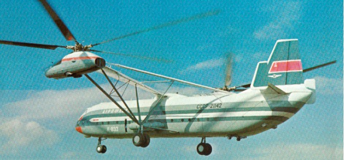
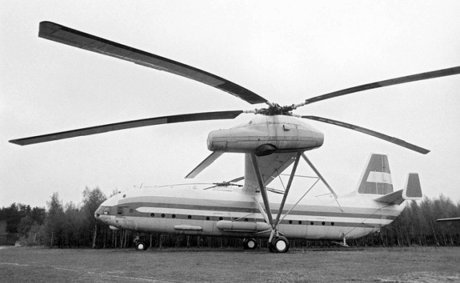
Although the requirement called for a tandem-rotor layout, Mil received early permission to concentrate instead on a twin side-by-side rotor configuration, which the design bureau claimed as having better reliability, fatigue life and stability. Thus the V-12, which first flew in the second half of 1968, appeared with a fuselage resembling that of a fixed-wing aircraft, from whose top spring two inversely tapered wings carrying the twin dynamic systems at their tips.
To avoid the task of developing new set of rotors, reduction gears and transmission, decision taken to double up Mi-6 dynamics and use two sets of Mi-6 engines, gearboxes and lifting rotors side-by-side, left rotor being mirror image, with small overlap.
The two engines are located side-by-side with twin intakes, and drive five-bladed metal rotors. The left rotor rotates anti-clockwise and the right unit clockwise; the two units are connected by transverse shafting to ensure synchronization and the continued rotation of both units in the event of engine failure at either wingtip. The lower part of each cowling can be dropped to form a working platform for mechanics.
The engines were 6500shp Soloviev D-25VF turbines giving the helicopter a maximum speed of 260km/h, with a 35400kg load and 500km range. The two 6500shp Soloviev D- 25VF turboshafts are uprated from the 5500shp of the Mi-6’s Soloviev D-25V by the addition of a zero stage to the compressor and by an increase of operating temperature. Rotor rpm reduced to 112; gearboxes linked by transverse shafting. Axes inclined forward 4deg 30min. Engine/rotor groups carried on wings of light-alloy stressed-skin construction with 8deg dihedral, sharp inverse taper and set at incidence 7deg root 14deg tip. Braced at root and tip to main landing gears with torque reacted by horizontal bracing to rear fuselage. Inner/outer trailing-edge flaps fixed in up position after flight trials. Fuel in outer wings and two external tanks; optional ferry tanks in cabin. Fixed twin-wheel landing gear with main tyres 1750 x 730mm, pneumatic brakes, and steerable nose tyres 1200 x 450mm. Large stressed-skin fuselage with crew door each side, three sliding side doors and full-section rear clamshell doors and ramp with left/right twin-wheel ventral bumpers. Aeroplane tail with fin, tabbed rudder, dihedralled tailplane with tabbed elevators, and endplate fins mounted vertically but toed inwards. Flight deck for pilot (left) with engineer behind and co-pilot (right) with elec-syst operator behind. Upper flight deck for nav with radio operator behind. Hydraulic flight control with emergency manual reversion. Autopilot with three-axis autostab; mapping radar under nose. AI-8 turbine APU for ground power and engine start. Main cabin 28.15m long, 4.4m square. Overhead gantry crane with four 1t hoists. Tip-up seats along sides (50 to 120).
Two V12 prototypes were built. Both prototypes had the same registration! This registration CCCP-21142 is in Cyrillic and means SSSR-75499. The first prototype was damaged in a heavy landing, but was repaired.
First hover 1967 terminated by impact with ground causing severe damage; cause coincidence of primary airframe aeroelastic freq with natural freq of control system, causing uncontrollable vertical oscillations.
The four Soloviev D-25 VF turboshaft engines had a combined output of 19388kW, enabling the V-12, first flown on 10 July 1968, to establish a series of records in February 1969. When submitted for ratification, was the first intimation received in the West of the existence of this giant helicopter. Later in the year, on 6 August 1969, the V-12 lifted a payload of 40204.5kg to a height of 2255m, establishing a record.
The first prototype was destroyed in a non-fatal landing accident during 1969, caused by engine failure.
The second prototype (21142, now at Monino), which was presented in the West at the 1971 Paris Air Show, and had set seven load-carrying records in 1969. On 22 February, a 31030kg load was lifted to 2951m and on August 6 1969, a load of 40,204.5kg was lifted to 2255m flown by Vasily Kolochenko. This was a new payload record for 2000m, and payload-to-height records for 35,000kg and 40,000kg.
No further development or production ensued.
The rebuilt first prototype Mil V-12 is located today next to the Mil Helicopter factory in Lyubertsi-Panki. The second prototype Mil V-12 CCCP-21142 is at the Central Museum of the Air Forces at Monino, located approximately 38 km from Moscow, Russia.
Mil V-12
Mil Mi-12 (V-12) Rotor dia: 114 ft 10 in (35 m) Overall rotors span: 67m Length: 121 ft 4.5 in (37 m) Height: 41 ft 0 in (12.5 m) Fuselage width: 4.4 m Engines: 4 x Soloviev D-25VF turboshaft, 6500 shp / 4780kW Empty weight: 60000kg Max TO wt: 231,500 lb (105,000 kg) Max level speed: 161 mph (260 kph). Cruising speed: 240km/h Service ceiling: 3500m Range: 800km Crew: 6-10
In 1937, a long range aircraft was in the development stage, Projekt 1061, which was to be powered by four individual engines, and have a range of 20000 km (12428 miles). Due to more important projects in development at the time (mainly the Bf 109 and 110), Projekt 1061 was only sporadically worked on until late in 1940. The German Naval Warfare Department wrote to Reichsmarschall Göring on August 10, 1940 that long range aircraft with a range of at least 6000 km (3728 miles) would be needed to reach the planned German Colonial Reich in central Africa. Also, about this time the RLM issued a requirement for long range aircraft with a range of at least 12000 km (7457 miles), to reach from French bases to the United States, in anticipation of the coming war with the U.S. Therefore, the work on Projekt 1061 was stepped up, with Willy Messerschmitt on December 20, 1940 informing designers Wolfgang Degel, Paul Konrad and Waldemar Voigt of the requirements for this long range aircraft.
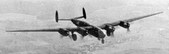
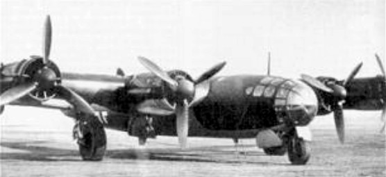
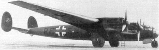
Three models were built. V1 (RE+EN) flew first in December 1942 with Junkers Jumo 211J-1 engines developing 1425 hp, it flew again on 2nd May 1944 with more definitive BMW 801G-2 engines. With a take off weight of 22000kg (48,400lb) it obtained a speed of 490km/h.at sea level. It spent a short time with Transportstaffel 5 and was eventually destroyed in an air raid at the end of the war.
V2 had BMW801G-2 engines, but was destroyed before it’s first flight in an air raid in 1943.
V3 was the forerunner for the Me264 A0 and was armed with MG131 and MG151 guns and had 3 Rb50/30 cameras, but was scrapped before the end of the war.
The “B” model was planned with 6 DB603 engines or with 4 BMW801E engines plus two BMW 018 turbojets.
The initial requirements were for a 20000 km (12428 miles) range, capability for military and civilian roles, at least a 5000 kg (11023 lbs) bomb load to be carried in an internal bomb bay, smaller bombs to be carried externally on under-wing pylons and to have a very clean airframe. In early 1941, Messerschmitt received an order to build six prototype Projekt 1061 aircraft, which were given the designation of Me 264. If the aircraft proved capable, a further 24 aircraft were to be built for “harassing attacks against the United States”. At the same time, Messerschmitt continued to work on a six engined version of the Me 264, Projekt 1075. Since the Messerschmitt design offices were running at full capacity, part of the design work was delegated to the Fokker Works in Amsterdam.
On January 22, 1941, the General Staff of the Luftwaffe demanded a long range aircraft for the submarine war. Because of its overoptimistic performance and weights data, the RLM chose the Me 264 as the best choice. Several schemes were proposed by the Messerschmitt design bureau to extend the range of the Me 264, including towing one Me 264 by another to altitude, in flight refueling by a second Me 264, adding two more engines bringing the total to six and using take-off rocket pods for overload takeoff conditions. With these recommendations, it was felt that a range of 18100 km (11247 miles) and a bomb load of 5000 kg (11023 lbs) could be achieved, and a range of 26400 km (16405 miles) without any bombload. Armament for both versions would have consisted of remote controlled turrets with either MG 131 or MG 151. In early 1942, GFM Milch canceled or reduced numerous development projects, including reducing the number of Me 264 prototypes from six to three, due to the worsening war situation. On February 28, 1942, the Me 264 development was to be temporarily turned over to the Dornier works, but they too were operating above their capacity. The Wesser Aircraft Works in southern Germany were also considered, but nothing came of this idea either. A commission headed by Lt. Col. Petersen arrived at the Messerschmitt-Augsburg complex on April 24, 1942 (at the orders of Milch) to check the actual performances of the Me 264, where it was found that the performances were about 90% of what Messerschmitt had been stating. Strangely enough, the very same day Willy Messerschmitt was cleverly presenting the RLM with the idea of using the Me 264 in “Atlantic Missions”, and harassing attacks on the American east coast. Shortly afterwards, on May 7, 1942, another detailed report was yet again submitted stating that the Me 264 with a takeoff weight of 45000 kg (99207 lbs) and powered by four Jumo 211J engines could attain a range of 13000 km (8078 miles), and with four BMW 801 engines a range of 14000 km (8700 miles) could be reached. To add to the confusion again, on May 16, 1942 a meeting was held concerning all long range aircraft. It was decided that any flights over 13500 km (8389 miles) would need in flight refueling, and General Jeschonnek had already turned down this option in February 1942 (even though initial in flight refueling tests with a Fw 58 and a Ju 90 had been successful). This ended (at this time) all discussions of harassing attacks against American targets, also reconnaissance missions over the Trans-Siberian railroad and even Equatorial Africa.
According to a study dated April 27, 1942, the long distance aircraft should be able to fly reconnaissance missions as far as Baku, Grosnyj, Magnitogorsk, Swerdlowsk, Tiffis or Tshejabinsk in the USSR, and flights to Dakar, Bathurst, Lagos, Aden and southern Iran were also reachable. Not only were New Jersey and New York in the U.S. within range, but also targets in Ohio, Pennsylvania and even Indiana; in addition, there were plans to station some Me 264s on Japanese bases on islands northeast of the Philippines, to fly reconnaissance missions as far as Australia, India and much of the Pacific area.
By mid-July of 1942, three Me 264 prototypes were being constructed. It was hoped that the Me 264 V1 could be ready for flight testing by October 10, 1942, but again this was optimistic due to delayed and sometimes missing component deliveries. By the end of August 1942 it was obvious that the October maiden flight could not be attained because of the excessive delay in the main landing gear delivery from VDM and the promised Junkers engines were also late. A general skepticism was creeping in concerning the numerous delays in getting the first Me 264 in the air, and again the consensus from the RLM and General Staff of the Luftwaffe was leaning towards the Junkers Ju 290 and the six engined Ju 390.
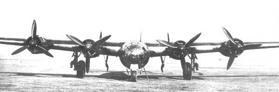
Meanwhile, the construction of the first prototype V1 was progressing very slowly at Augsburg. At last, on December 23, 1942, the Me 264 V1 was ready for its first test flight, which lasted 22 minutes. The landing gear was left down due to safety concerns. The test flights were later made at Lechfeld, because it had a sufficiently long concrete runway to accommodate the large Me 264, but could test only the first prototype due to the fact that the airfield facilities only had one hanger large enough to house the Me 264 V1.
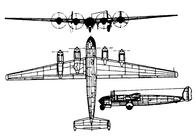
The Me 264 V1 had a very “clean”, all metal fuselage with a circular cross section throughout. Just behind the extensively glazed nose and cockpit was a galley, crew rest area and walkway to the rear of the plane above the lower, enclosed bomb bay. The wings were shoulder mounted, slightly swept back and tapered. They contained a single main spar and one auxiliary spar, with the wing loads being transferred through the main spar and two auxiliary bulkheads into the fuselage. The entire fuel supply was stored in the large wings. All control surfaces were conventional, including split flaps on the inner wing. The tailplane, with its twin fins and rudders, was electrically adjustable during flight. A tricycle landing gear system was designed, which was unusual for such a large aircraft at this time. A single nose wheel was used, although testing had been done for a twin nose wheel configuration using a converted Bf 109 (work number 5603). The test showed a loss of manoeuvrability, but no shimmying. Because of the ever increasing weight demands, the main landing gear was also to be strengthened, and even a droppable auxiliary main gear was considered. The exterior of the Me 264 V1 was puttied and sanded all over, to give the smoothest possible finish. The engines used on the first prototype were the 12 cylinder, liquid cooled Junkers Jumo 211J-1 . These were the same engines used on the Junkers Ju 88A-4 models, and to save time even the Ju 88 nacelles and radiators were utilized. The Me 264 V2 was to have extended wing tips and 1000 kg (2200 lbs) of armor added around the more vital parts of the aircraft. It was reportedly being readied for preflight ground tests when it, too, was destroyed in an air raid.
During the flight testing in 1943, the fate of the Me 264 still hung in the balance. Admiral Dönitz and the Supreme Naval War Staff favored the Focke-Wulf Ta 400. However, since this aircraft wasn’t supposed to be ready before 1946, it was decided that the Ju 290, He 177 and the Ju 390 should be produced in the interim to provide maritime reconnaissance. A teletype message reached Messerschmitt in May 1943, stating that the Me 264 should be abandoned. This caused some astonishment, because just a week earlier the RLM had insisted upon the completion of the Me 264 prototypes. In June 1943, Messerschmitt contacted Hitler to inform him on how well the Me 264 development was progressing, hoping that Hitler would intervene in his behalf. On July 8, 1943, at a meeting in the Supreme Headquarters, Hitler promised his support for the continued production of the Me 264 to Messerschmitt, but only for maritime uses. At the same time he dropped his decision to bomb the east coast of the U.S., because “the few aircraft that could get through would only provoke the populace to resistance”. Only one day later, GFM Milch agreed to continue the construction of the three Me 264 prototypes for the purpose of studies only. Göring, Milch, Friebel and Messerschmitt met on October 14, 1943 to discuss further development possibilities. According to Messerschmitt, the components for the first five prototypes were completed, but he lacked the necessary space and facilities in which to construct them. To get the space for the Me 410 production, all the Me 264 final assembly building jigs were moved from the Augsburg plant and stored at Gersthofen. Later that day, GFM Milch wanted to stop the Me 264 completely, in order to concentrate on the Me 262 jet fighter, to which Göering agreed. One day later, the production orders for the Focke-Wulf Ta 400 was cancelled, mainly because the Focke-Wulf resources were needed for the Fw 190D-9 and Ta 152 production.
On June 29, 1944, the Trial Establishments Headquarters definitely stated that the Me 264, as well as the Ju 390, would be unsuitable for operational deployment since its fitting with the entire military equipment and payload would excessively increase the takeoff weight and the wing load. Then on July 18, 1944 the only Me 264 prototype was destroyed in an air raid along with the assembled components of the following two prototype and 80% of the production facilities. Although numerous attempts were made to save the Me 264 program, Admiral Dönitz got Hitler to agree on September 23, 1944 that all work on the Me 264 project should be stopped. Less than a month later, on October 18, 1944 an unmistakable directive was received. The “Reichsmarschall Technical Order Nr. 2” stated: “The production of the Me 264 is herewith cancelled”. This confirmed the end of the eight year development program that led to only one test aircraft that was far from being operationally ready.
The V4 model was planned to use four high performance BMW 801 E engines with turbochargers and GM-1 boost system. Another idea was a provision as a long range transporter, which would carry 12 to 17 paratroopers and be armed with one FLH 151Z remote controlled turret. It was considered that two additional drop tanks could extend the Me 264’s range to 13600 km (8451 miles) and a top speed of 580 km (361 mph) at an altitude of 6300 meters (20700 feet), with an estimated flight time of 41 hours. Another version was to add two Jumo 004 jet engines outboard of the four radial BMW engines, and was submitted to the Luftwaffe for evaluation. It was even considered to include a towed Me 328 pulsejet powered fighter for protection.
A variety of engines were considered for the Me 264, including a four Jumo 004C jet engined version, a two or four BMW 028 turboprop engined version and a twin BMW 018 turbojet powered version. Another project was to have used Ritz heat exchangers to greatly increase range. The most unusual powerplant idea was for a steam turbine that was to develop over 6000 horsepower. Fed by four boilers and driving one of two forms of propeller – the first, of 17.5 ft (5.4 m) diameter, revolving at 400 500 rpm, the second, only 6.5 ft (2.0 m), turning at 6,000 rpm, fuel would have been in a mixture of powdered coal and petroleum. The main advantages to this engine would be constant power at all altitudes and simple maintenance. The Me 264 so allocated was destroyed in an air raid.
An armed long distance reconnaissance version (Me 264A) would have been equipped with three Rb 50/30 cameras, and armed with one MG 130/2, one DHL 151Z, one MG 151 and perhaps two MG 131 for the lateral positions.
The long range bomber version (Me 264B) was supposed to be fitted with four BMW 801E radial engines and an additional two Jumo 004C jet engines. The armament was similar to the above reconnaissance model, except the single MG 151 would be replaced with one MG 131. Its total weight would be 48100 kg (106041 lbs), or 49900 kg (110010 lbs) with the two Jumo 004C jet engines. The range would have been, with a 3000 kg (6614 lbs) bomb load, 11600 km (7208 miles) without the Jumo jet engines and 8500 km (5282 miles) with the jets. With the jet engines installed, the aircraft should have been able to reach a top speed of 655 km/h (407 mph) at 6700 meters (21981 feet). A top ceiling of 14500 meters (47572 feet) could be reached due to the pressurized cockpit. A naval version would be equipped with four Jumo 222E/F high altitude engines, plus the two Jumo 004C turbojets. the maximum offensive load was calculated to be 6000 kg (13228 lbs). It was also recommended at this point that the fully glazed cockpit should be replaced with a stepped cockpit, also, the defensive armament was being continually revised until all the turrets were remotely controlled, and revolved through 360 degrees. A new turret was even developed, armed with two MG 213 revolver cannon, then under development.
There was also a high altitude bomber version being designed, which would have been equipped with four BMW 801 E/F radial engines with superchargers. The cockpit was planned to be pressurized from the beginning. Since the rest of the plane would not be pressurized, remote controlled defensive armament would have to be installed. According to factory documents of July 9, 1943, this version was based on a 39000 kg (85979 lbs) takeoff weight, which included a 3000 kg (6614 lbs) bomb load, and was to utilize the jettisonable additional landing gear. The minimum penetration distance would have been 3500 km (2175 miles) at an altitude of 12000 meters (39370 feet), at a cruising speed of 640 km/h (398 mph). It would have required a climbing time of 70 minutes to reach this altitude. Again, the Jumo 222 E/F would have been the most efficient engines for high altitude operations, and it was planned to re-equip this aircraft when these engines became available.
5100 kg (11243 lbs) drop tanks were designed in September 1944, and were ready to be manufactured when the cancellation order arrived. Even after the cancellation order was received, work continued by many Messerschmitt engineers and designers in December 1944 on a courier version of the Me 264, with a range of 12000 km (7457 miles) and a load of 4000 kg (8818 lbs). At this point in time, the work done was merely a way to protect the Messerschmitt employees from being conscripted into the army.
Messerschmitt Me 264 V1 Flight Tests
December 23, 1942 Test Pilot: Karl Baur Airfield: Augsburg After extensive taxiing trials, the Me 264 made its maiden flight. The duration of this first flight was 22 minutes, and for safety reasons the landing gear was left down. On landing, the airframe was damaged in the area of the flap mounts when the aircraft rolled over the end of the runway due to the failure of the brake system.
January 20, 1943 Test Pilot: Karl Baur Airfield: Augsburg The second test flight was made. Karl Baur complained that the forces on the controls were too high, about the poor placement of the instruments and of exhaust fumes penetrating into the cockpit.
January 22, 1943 Test Pilot: Karl Baur Airfield: Augsburg The Me 264 was transferred to Lechfeld.
January – February, 1943 Test Pilot: Karl Baur Airfield: Lechfeld On the fifth test flight, the underside of the fuselage was damaged when it accidentally contacted the ground. Also, the hydraulic system of the landing gear failed, making it impossible to retract the gear.
February, 1943 Test Pilot: Karl Baur Airfield: Lechfeld Baur reported some problems with the inner flaps and a defective nose wheel. Despite some changes to the control surfaces, the forces against them were still too high and the changes had displaced the center of gravity. The nose wheel problems were fixed, and now the retraction functioned properly. Also, some minor defects were found in the electrical cables of the intercom system.
February, 1943 Test Pilot: Gerhard Caroli Airfield: Lechfeld Caroli also found that the forces against the control surfaces were still too high, especially at high speed. Small defects were still present in the radio system and landing gear.
February, 1943 Test Pilot: Karl Baur Airfield: Lechfeld During two flights by Baur, a speed of 600 km/h (373 mph) was reached. The faulty trimming and controls revealed that an eventual change in the entire control system would be inevitably needed. Flights with two or three engines were found to be satisfactory, but in flights with the automatic controls it was found that the servos were too low powered to control such a heavy aircraft.
March 2, 1943 Test Pilot: Karl Baur Airfield: Lechfeld Stability tests were continued.
March 4, 1943 Test Pilot: Karl Baur Airfield: Lechfeld A test of the polare system was cut short when after 15 minutes of flying time, the third engine began to smoke and had to be cut out. At this time, 11 test flights had been made totaling 12 hours flight time.
March 23, 1943 Test Pilot: Karl Baur Airfield: Lechfeld After the faulty engine was changed, the critical altitude tests were made. Several other test flights were made this day, mainly to check the longitudinal stability. Also, the first measures to improve the rudder effect was made.
March 23, 1943 Test Pilot: Karl Baur Airfield: Lechfeld During landing, the left oleo leg broke, which was probably not fully locked down, causing some damage.
March 23 – May 21, 1943 Airfield: Lechfeld During repairs, a new steering column, a reinforced wing skin, a modified nosewheel drive and a complete radio were added. Also, a new emergency tail skid was added, a changed tailplane and four new Jumo 211J engines were installed.
May 22 – June 5, 1943 Test Pilot: Karl Baur Airfield: Lechfeld Continued high forces against the ailerons and rudder surfaces were found. Six flights were made totaling 12 hour 16 minutes.
June 2, 1943 Test Pilot: Flight Capt. Wendel Airfield: Lechfeld Serious problems arose when the nosewheel jammed during retraction.
June 10, 1943 Test Pilot: FBM Böttcher Airfield: Lechfeld Reported that the cockpit excessively heated up in the summer sun.
August 11, 1943 Airfield: Lechfeld The Me 264 V1 was taken out of service, and re-equipped with BMW 801 twin row radial engines.
March 18, 1944 Airfield: Lechfeld The Me 264 V1 was slightly damaged in an air raid, and was quickly repaired.
April 14, 1944 Airfield: Lechfeld During the first test roll with the new engines, the brake shoes tore off.
April 16, 1944 Airfield: Lechfeld The Me 264 V1 was transferred to Memmingen.
April, 1944 Airfield: Memmingen During the 38th test flight, the emergency skid was torn out after a rough landing. When the rudders were fitted with balances, the excessive vibrations almost ceased.
late April, 1944 Test Pilot: FBM Scheibe Airfield: Lechfeld Scheibe, from the Rechlin Trial Establishment, complained about the canopy reflections during his test flight. He also indicated that the excessive airframe vibrations were the number one problem to fix.
late April, 1944 Test Pilot: Colonel Barsewich Airfield: Memmingen Barsewich, from the Chief Reconnaissance Department, judged the Me 264 V1 too slow for combat missions, even though the aircraft was about 10% faster than with the Jumo 211J engines.
early May, 1944 Test Pilot: Lt. Colonel Knemeyer Airfield: Memmingen After an uneventful flight, Knemeyer was completely enthusiastic about the Me 264, in his opinion all problems could be overcome in the further testing and refinement of the aircraft.
April 17 – May 17, 1944 Test Pilot: Karl Baur Airfield: Memmingen Flight testing was performed for tailplane flutter and the emergency tail skid. The rear of the plane was found to be too heavy.
April 26 – May 3, 1944 Test Pilot: Captain Nebel Airfield: Memmingen Three test flights were made by Capt. Nebel of the Rechlin Test Establishment to finally redress the tail vibrations. To avoid building an entire new tail, balance weights were added to get the vibration problems under control. Since the problem was not solved, a larger tail plane seemed inevitable.
June 5, 1944 Test Pilot: Karl Baur Airfield: Memmingen More stability tests were made, with a small improvement. However, the flights were complicated by the continuous problems with the Patin system.
June 6, 1944 Test Pilot: Karl Baur Airfield: Memmingen Extreme rudder fluttering was found in the 380 – 450 km/h (236 – 280 mph) range. Also criticized were the too soft automatic controls, which had to be adjusted again.
June 26, 1944 Test Pilot: Karl Patin Airfield: Memmingen A climb flight with combat performances was prematurely cut short when the fuel pressure of both inner engines fell to zero. After checking the fuel pumps, several defects were found. Also, the failure of the Patin, radio and electrical systems caused intensive repairs.
July 18, 1944 Airfield: Memmingen The Me 264 (RE+EN, work number 264000001) was damaged during an air raid. The extent of the damages was too severe for the damage to be repaired.
Specifications:
Messerschmitt Me 264 V1 Span: 38.9 m /127 ft 7 in Length: 20.115 m / 66 ft Height:4.3 m / 14 ft 1 in Wing Area: 127.7 sq.m / 1374.56 sq.ft Fuselage Diameter: 2.2 m / 7 ft 3 in
Messerschmitt Me 264 V3 Span: 43 m / 141 ft 1 in Length: 20.115 m / 66 ft Height:4.3 m / 14 ft 1 in Wing Area: 127.7 sq.m / 1374.56 sq.ft Fuselage Diameter: 2.2 m / 7 ft 3 in Empty Equipped Weight: 23360 kg / 51500 lbs Crew (6) Weight: 540 kg / 1191 lbs Fuel Weight: 19700 kg / 43438 lbs Oil Weight: 1260 kg / 2778 lbs Nitrous Oxide Weight: 680 kg / 1500 lbs Normal Loaded Weight: 45540 kg / 100416 lbs Max. Auxiliary Fuel & Tanks Weight: 10500 kg / 23152 lbs Max Overload Weight: 56040 kg / 123568 lbs Jettisonable Takeoff Equipment Weight: 4300 kg / 9481 lbs Cruising Speed: 350 km/h / 218 mph Max Speed: 545 km/h / 339 mph Service Ceiling: 8000 m / 26240 ft Max Range: 15000 km / 9315 miles Max Endurance: 45 hours Climb Rate (overload): 120 m/min / 393 ft/min. Landing Speed: 160 km/h / 99 mph Takeoff Run (Normal Load w/ RATO): 1500 m / 4920 ft