Gloster F.9/40 / G.41 Meteor

Meteor F.8

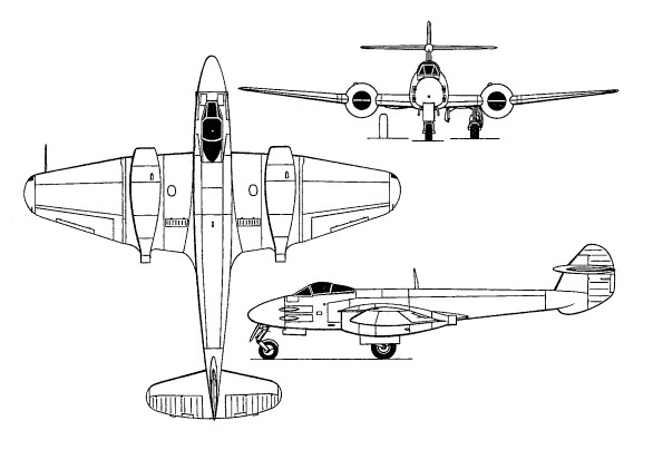
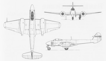
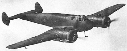
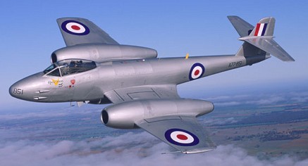
Designed by George Carter, the Gloster Meteor began life in response to Specification F 9/40, which called for a single-seat interceptor. The jet engine was still very much in its infancy when this project got under way and the low thrust available from early powerplants of this type necessitated the adoption of twin-engine layout from the outset. Under the impetus of war, design progress was swift and was rewarded with a contract for 12 prototypes in February 1941, although only eight of these prototypes were eventully completed.

Gloster F.9/40 / G.41 Meteor Article

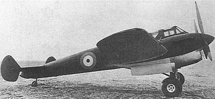
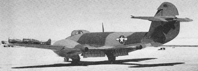
The eight original F.9/40 airframes were used to test several different types of British gas turbines including the Rover-built Power Jets W2B, the parent design of the Rolls-Royce Welland with which the Meteor I was fitted; the Metropolitan Vickers F.2/1, the first British axial-flow unit to fly (13 November 1943); the Halford H.1, the predecessor to the de Havilland Goblin; and the Rolls-Royce Trent, the first turboshaft engine to fly. Actually the 6530kg Halford-engined F.9/40 was the first version of the Meteor to fly (on 5 March 1943) as the W2B engines (4360kg) installed in another F.9/40 in July 1942 were not ready for flying until June 1943.

The eight prototypes built (DG202 – DG209) were used for both airframe and powerplant development trials. Due to difficulties with supplies of the first jet engines the first flights of the prototypes were spread over several years with the last of them flying after the first F.Mk I’s were in service with the RAF.

Developmental aircraft –

DG202
First Flight: 24th July 1943
Rover W.2B/23 turbojets.

DG203
First Flight: November 1943
First flown in 1943 with two Power Jets W.2/500’s. Its next flight was almost a year later in October 1944 with more powerful W.2/700’s.

DG204
First Flight: 13th November 1943
Metropolitan-Vickers F.2, Axial-Flow turbojets, crashed 1st April 1944 after just 3 hours 9 minutes flying time.

DG205
First Flight: 12th June 1943
Rover W.2B/23’s, second to fly.

DG206
First Flight: 5th March, 1943
First to fly. de Havilland Halford H.1 turbojets (2,700 lbs thrust).

DG207 (prototype Meteor Mk II)
First Flight: 24th July 1945
de Havilland H.1 Goblin, later became the prototype F. Mk II.

DG208
First Flight: 20th January 1944
First to be fitted with dive brakes and Rolls Royce W.2B/23 engines.
Modified fin and rudder

DG209
First Flight: 18th April 1944
Early version of W.2B/37 Derwent I.

Although the first flight of a Meteor was with the de Havillands turbojet, production Meteors were powered by engines developed by Rover and later Rolls-Royce W.2B/23 Welland 1 reverse-flow turbojets with centrifugal-flow compressors, with the de Havilland engines allocated entirely to Vampire production which entered service shortly after the end of WW II. Trials with the Metropolitan-Vickers engines also were not wasted despite being cut short by the crash of DG204 and plagued by early problems as the F.2 developed into the successful Beryl turbojet and led directly to the Armstrong Siddeley Sapphire two of which were fitted to a Meteor making it the most powerful ever to fly.

The first of these began taxi trials with four types of engine in June 1942 but it was not until 5 March 1943 that the type took to the air for the first time, this maiden flight being made by the fifth prototype. By then, the Meteor had been ordered into production.

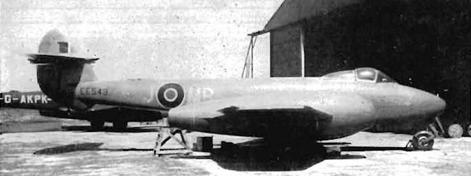
Only twenty Mk I’s were built, sixteen of them serving with RAF. Two of the three prototype Mk I’s EE211 & EE212 were delivered to RAE Farnborough for trials and design development, while the first EE210 (First flight 12th January 1944) was delivered to Muroc AFB in exchange for an example of the Bell X59 Airacomet.

Gloster Meteor I EE210/G first production model at Muroc, Spring 1944

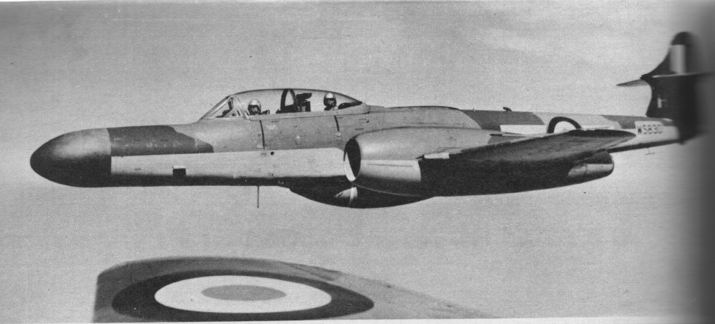
The /G (guard at all times) and prototype designation on the fuselage are still carried by DG202 at Cosford today. EE211/G was the second production Meteor, an F.Mk 1. Armed with four 20-mm cannon andpowered by two Wellan d I turbojets, it could reach a speed of 668 km/h (415 mph). Meteors provided good training for American bomber crews now faced with attacks from Me 262s.

616 Squadron at Cultrihead took delivery of the next ten EE213 – EE222 and the four aircraft EE224 – EE227 in July 1944. The last two deliveries EE228 & EE229 being attrition replacements for EE224 & EE226 with the latter crashing just two days after delivery. The first took delivery of the Meteors at Culmhead on the 12th July 1944 moving shortly afterwards to Manston in Kent where they started operations against the V1 flying bombs.

The squadron then moved to Manston where they would later take the Meteor into Europe although they were prohibited from flying over enemy lines because of the secrecy of the materials used in the engines. At 2.30pm on Thursday 27 July 1944, an RAF Gloster Meteor of No.616 (South Yorkshire) Squadron left its airbase at Manston, Kent, to make its first anti-V-1 patrol flight over the Channel, but it met no flying bombs. Shortly after, two more Meteors took off, and Sqn.Ldr. Watts saw a V-1, overtook it near Ashford, and pressed the firing button; but the guns jammed and the V-1 got away

On 4 August 1944 Meteor III won its first aerial victory, when Flt.Lt. P.J. Dean met a V-1 flying bomb about 3.5 miles south of Tonbridge, Kent. His Meteor cannon jammed repeatedly, so he knocked the flying bomb off course with his wings and made it crash. Several minutes later a second Meteor pilot, Fl.Off. J.K. Roger, reported that he too had downed a V-1 near Tenterden, Kent. Starting 11 August, 616 kept two Meteors on patrol duty throughout the day; each pair would patrol for 30 minutes while two more waited to take off and replace them. The squadron later moved to Belgium where it was joined by No. 504 Squadron with Meteor Mk III aircraft, also with Welland engines, but fitted with sliding hoods.

Meteor F.III EE245 No.15 Sqn Derwent engines

A Meteor was also used in the first tests of a ground level ejection seat.
The production Meteor F.1 was powered by two 7400kg Rolls-Royce Welland 1 turbojet engines and had a cockpit canopy that was side-hinged.

Meteor F.I of 616 Sqn July 1944

At RAE Farnborough EE211 was fitted with a pair of Powerjets W2/700’s and long cord engine nacelles which improved its high speed performance while at Rolls Royce EE223 in addition to being the first Mk 1 to have a pressure cabin for high altitude flight was also fitted with the more powerful W2B/37 Derwent I’s. The most interesting developmental Mk I was EE227, on its retirement by 616 Squadron in favour of the Meteor Mk III it became the world’s first turboprop, powered by a pair of Rolls Royce Trent’s.

The only Meteor F Mk II was the prototype based on DG207, also designated the G.41B it was powered by two DH Halford H.1 engines but did not enter production because its H1 engines (later known as the Goblin) were instead allocated to DH Vampire production following greater success with the W2/B Welland & Derwent designs after Rolls Royce became involved in engine production.

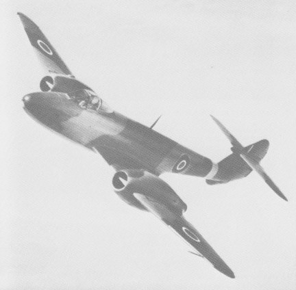
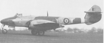
The first volume production version of the Meteor was the Mk III (G.41C) with a total of 210 aircraft built.
Similar to the MK I except for the new sliding Malcolm canopy and slotted airbrakes it had a strengthened airframe to absorb the additional power from the 2,000 lb thrust Derwent I engines. Due to production difficulties the first 15 had to make do with W.2B/23 Welland engines although some of these aircraft may have been retrofitted later once sufficient engines were available. These early aircraft almost all operated by 616 Squadron can be distinquished from the Derwent powered Meteors due to their slightly longer jet-pipe which protruded from the rear of the nacelle to a greater extent.

The Meteor F.Mk III saw operational service with 504 Squadron as well, being mainly em¬ployed in ground attack duties, but only a few of the 280 Meteor F.Mk IIIs built had entered service by VE-Day. Many of the first Meteor F. Mk III deliveries were painted white. This may have been an effort to prevent the Meteor from being mis¬taken for a German jet, as was the only No.616 Sqn Meteor F. Mk 1 to be shot at in the first three months (by a Spitfire).

The standard engines were two 8720kg Rolls-Royce Derwent Is, although the first 15 Mk 3s were fitted with Wellands. Sliding cockpit hoods were standard and provision was made for a long-range fuselage drop tank. The last 15 F.3s were fitted with the lengthened engine nacelles standardised on the Mk 4.

Many F Mk III’s were used in aviation research either directly from the Gloster production line or after squadron service including EE416 which went to Martin-Baker for ejection seat trials. Two others were fitted with strengthened undercarriage and a V Frame arrestor hook for deck landing trials on HMS Immplacable.

One of the thirty F Mk. III’s allocated for tests and trials showed the benefit of increasing the chord (length) of the engine nacelles. With the longer nacelles there was less compressibility buffetting at high speeds leading to an increase in the redline speed at 30,000 ft of 75 mph. As a result of these tests the last fifteen F Mk. III’s were delivered with longer nacelles. The increased power of the Derwent engine and this performance improvement led directly to the Meteor F4 and its successful attempt at the world absolute air speed record.

Two F Mk III’s were evaluated by foreign air forces with Mk III, EE311 going to the RCAF although it didn’t last long, running out of fuel and being ditched in June 1946. The second aircraft was operated for some years by the RNZAF. Re-serialled NZ6001 it was demonstrated throughout New Zealand from late in 1945 and eventually purchased for £5,000. It later became an instructional airframe and was scrapped in 1957.

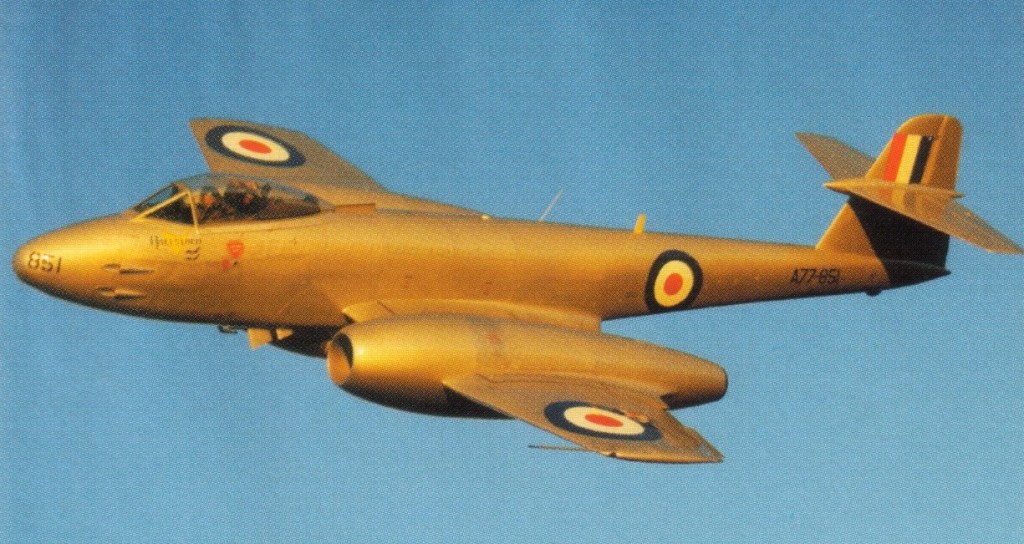
In May 1946 a F.3 Meteor was taken on charge by the Royal Australian Air Force, becoming the first RAAF jet fighter. It was not until 1951 that Meteors entered regular service with the RAAF and then they did so with a true “baptism of fire”. Meteor F.8 aircraft were taken into action by 77 Squadron RAAF, in Korea, against the Mig-15.

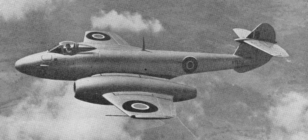
Production then switched to the Meteor F.Mk 4 with much more powerful engines, 583 being built be-tween 1945 and 1950.The first example flying on 12 April 1945. Power was provided by two Derwent 5 engines and the wing span was reduced to 11.33m to improve the rate of roll. Other features included long engine nacelles, pressure cabin, and fittings for bombs and rocket projectiles. An aircraft of this version set up world speed records on 7 November 1945 and 7 September 1946, flown by Group Captain E. M. Donaldson, of 975km/h and 991km/h respectively.

Meteor 4 – 1948

Gloster G.41 Meteor High Speed Flight

The Meteor 4 once used by Air Chief Marshal Sir James Robbs as his personal aircraft.

The private venture Meteor T.7 was a two-seat training version of the Mk 4, with the forward fuselage lengthened by 0.76m to accommodate tandem cockpits under a continuous canopy. No armament was carried. The first T.7 flew on 19 March 1948 and over 600 were built.

In the markings of the Brazilian Air Force, Meteor 7s were used in Britain to train Brazilian pilots. Brazil purchased 70 Meteor fighters and trainers.

Brazilian Gloster Meteor 7s

The F.8 was the most built of all Meteors with 1,522 being produced, first flown on 12 October 1948.

F.8

The F.8 differed in having a lengthened fuselage, redesigned cockpit and tail assembly.

The F.8 established international point-to-point records on London-Copenhagen, Copenhagen-London and London-Copenhagen-London in 1950 and in the following year set up a new international speed record over a 1,000km closed circuit of 822.2km/h.

The FR.9 and PR.10 were fighter-reconnaissance and unarmed photo- reconnaissance variants, the PR.10 having a similar nose and cockpit to the FR.9 but a 43 ft wingspan and an F.4 tail.

By 1950 the Meteor F.Mk 8 was well established in service, this model also being built under licence in Belgium and the Netherlands, embracing powerful Derwent engines, modified cockpit and canopy.
1090 F.8s were built.

Other single-seater variants included the Meteor FR.Mk 9 fighter-reconnaissance version of the Mk 8, and Meteor PR.Mk 10 unarmed version for high-altitude reconnaissance aircraft.

In addition to seeing widespread service as a day fighter, the Meteor also successfully adapted to night-fighter tasks, albeit as a two-seater. The initial variant engaged in this mission was the Meteor NF.Mk 11, the design of which was undertaken by Armstrong Whitworth was first flown in May 1950. The NF.11 had the longer span wing of the photo-reconnaissance Meteor, a lengthened nose to house the radar, tandem cockpits, and the tail of the F.8 day fighter. The four 20mm guns were transferred outboard of the nacelles. The NF.11 weighed about 14 ton at MAUW which included 700 gallons of fuel, two integral tanks of 375 gallons, an external ventral of 175 gallon, usually permanently fitted and two 100 gallon wing tanks. The NF.11 being succeeded by the Meteor NF.Mk 12 of April 1953 had a lengthened nose and improved radar, and a faired tail bullet which effectively increased fin area with a different radar, the NF.Mk 13 with tropical equipment, and the Meteor NF.Mk 14 was tested late in 1953 with a clear-vision canopy and other refinements.

The Meteor NF.14 Night Fighter was the last major development of the line. The NF.14 was a two-seat, twin-engined monoplane, powered by two Rolls-Royce Derwent 8 turbojets, each delivering 3,600 lb thrust. The service ceiling was 40,000 feet and the maximum speed was 579 mph. Its range, with ventral and underwing tanks, was approximately 950 miles at altitude. A ventral fuel tank was normally carried and two under-wing tanks of 100 Imp.Gal. were optional.

Meteor night-fighters were used for experimental launching of guided missiles.

Night-fighter production by Armstrong Whitworth totalling 547 aircraft.

Production of night-fighter variants eventually totalled 578, some later being modified for target towing duty as the Meteor TT.Mk 20 whilst many single-seaters served as Meteor U.Mk 15, Meteor U.Mk 16 and Meteor U.Mk 21 drones developed by Flight Refuelling Ltd.

The Meteor proved a success and over a thousand of the new fighters were built to re-equip twenty Fighter Command squadrons and ten squadrons of the Royal Auxiliary Air Force.

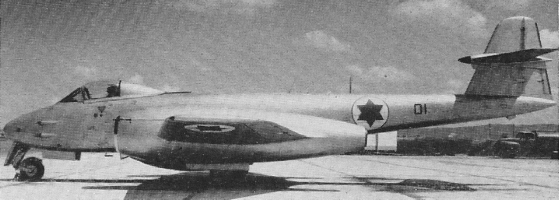
A total of 3,545 Meteors was produced by Gloster and Armstrong Whitworth., more than 1,100 of which were F.8s. Meteors were also exported in considerable numbers for service with the armed forces of Argentina, Australia, Belgium, Brazil, Denmark, Ecuador, Egypt, France, Israel, the Netherlands and Syria.

Argentine Meteors

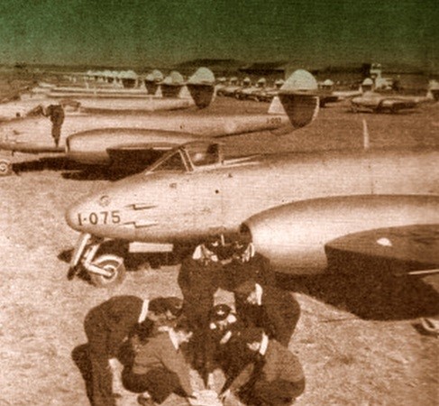
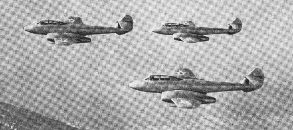
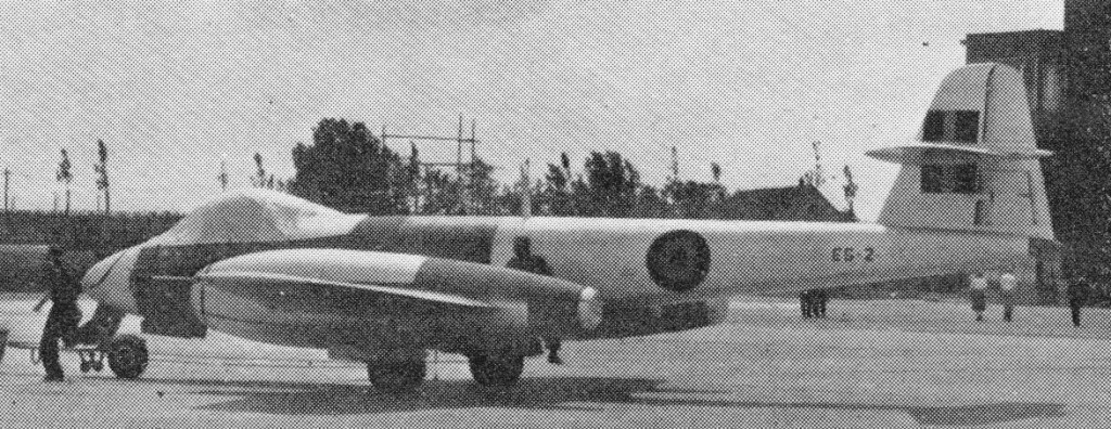
Part of the group of Gloster Meteors that Argentina bought from England in the beginning of the 1950s to serve as interceptors. The Air Force ordered 100 F4, 50 were ex-RAF, 50 were new. It was due to a large debt that England owed to Argentina that the airplanes were acquired. England could not pay the debt outright so arrangements were made for the airplanes.

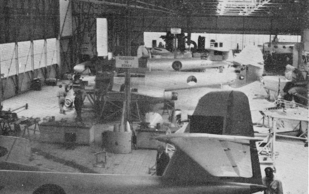
The Fokker assembled Meteor 8 (the first from British parts) were powered by Rolls-Royce Derwent 8s built in Belgium.

First Fokker assembled Meteor 8

By July 1950 production of 300 Meteor 8, to be evenly divided between the Dutch and Belgian Air Forces was underway at Fokker.

Two Belgian Meteor 8 and a Dutch Meteor 4 at Schiphol

To investigate a prone piloting position a Meteor F.8 was converted by Armstrong Whitworth circa 1955 to feature a prone position in a special elongated nose. Aft is a normal cockpit with a safety pilot. The prone-pilot Meteor was flown extensively from Baginton and Farnborough.

Gallery

G.41 Meteor F. I
Engines: two 771-kg (1,700-lb) thrust Rolls-Royce Welland 1 turbojets
Maximum speed: 668 km/h (415 mph) at 3050 m (10,000ft)
Service ceiling: 12190 m (40,000 ft)
Empty weight: 3692 kg (8,140 lb)
Maximum take-off weight: 6257 kg (13,795 lb)
Wingspan: 13.11 m (43 ft 0 in)
Length: 12.57 m (41 ft 3 in)
Height: 3.96 m (13 ft 0 in.)
Wing area: 34.74 sq.m (374.0 sq ft)
Armament: four nose-mounted 20-mm Hispano cannon (provision for six)
Crew: 1

Gloster G. 41 Meteor F.I
Engines: 2 x Rolls Royce W.2B/23C Welland, 7564 N / 771 kp
Length: 41.24 ft / 12.57 m
Height: 12.992 ft / 3.96 m
Wingspan: 43.012 ft / 13.11 m
Wing area: 373.941 sq.ft / 34.74 sq.m
Max take off weight: 13796.7 lb / 6257.0 kg
Weight empty: 8140.9 lb / 3692.0 kg
Max. speed: 361 kts / 668 km/h
Service ceiling: 39993 ft / 12190 m
Wing loading: 36.9 lb/sq.ft / 180.0 kg/sq.m
Range: 1164 nm / 2156 km
Crew: 1
Armament: 4x 20mm MG

Meteor F.III
Engines: 2 x 2,000lb Rolls Royce Derwent IV Turbojets
Span: 43ft
Length: 41ft 3in.
MAUW: 14,750 lb
Maximum speed: 415mph at 30,000ft
Service Ceiling: 40,000ft
Rate of Climb: 3,300ft/min
Range: 510 miles
Armament: 4 x 20mm Hispano cannon

F.4
Engines: 2 x Rolls-Royce Welland, 1700 lb.
Wing span: 37 ft 2 in (11.33 m).
Length: 41 ft 4 in (12.6 m).
Height: 13 ft 0 in (3.96 m).
Max TO wt: 15,175 lb (6883 kg).
Max level speed: 585 mph ( 941 kph).

F.8
Engines: 2 x 1633-kg (3,600-lb) thrust Rolls-Royce Derwent RD.8 turbojets.
Wingspan 11.33 m (37 ft 2 in)
Wing area 32.52 sq.m (350 sq ft)
Length 13.26 m (42 ft 6 in)
Height 4.22 m (13 ft l0 in)
Empty weight 4846 kg(10,684 lb)
Maximum take-off 7836 kg (17,275 lb)
Fuselage Tank Capacity: 330 Imp Gal / 1,500 lt / 396 U.S. Gallons
Ventral Tank Capacity: 175 Imperial Gallons / 796 Litres / 210 U.S.Gallons
Maximum speed 953 km/h (592 mph) at sea level
Initial climb rate 2134 m (7,000 ft) per minute
Service ceiling 13410 m (44,000 ft)
Range, clean 1110 km (690 miles)
Range: 767 mi at 40,000 ft
Armament: four 20-mm Hispano Mk V cannon / Two 1000lb (455 kg) bombs or eight 60 lb (27.3 kg) air to ground rockets.
Wheel track: 19 ft 5 in
Wheelbase: 13 ft 4 in

PR.10
Engines: 2 x Rolls-Royce Derwent R.D.8, 3600 lb
Wingspan: 43 ft
Length: 43 ft 6 in
Height: 13 ft 10 in
Wing area: 350 sq ft

NF.11
Engine: 2 x Rolls-Royce Derwent, 3500 lb.
Fuel cap: 375 internal (+375 external) Imp.Gal.
Armament: 4 x 20mm Hispano cannon.
Max speed: 520 kts (430 kts with wing tanks).

Meteor NF.14
Engines: 2 x Rolls-Royce Dewent
Span: 43 ft
Length: 49 ft 11 in
MAUW: 20,000 lb approx
Max speed: 590 mph approx

Meteor F.III
F.8

Gloster F.9/37

Designed by W G Carter to Specification F.9/37 calling for a twin-engined single-seater, this Gloster fighter was of all-metal stressed skin construction. It was intended to carry a fuselage-mounted armament of two 20mm Hispano cannon and four 7.7mm Browning machine guns.

Two prototypes were ordered, the first of these, powered by two 1050hp Bristol Taurus T-S(a) 14-cylinder radials, being flown on 3 April 1939. The aircraft attained a maximum speed of 579km/h at 4575m, but was badly damaged in a landing accident early in its flight test programme. When testing was resumed in April 1940, it had been re-engined with 900hp Taurus T-S(a) IIIs with the result that performance suffered, maximum attainable speed in level flight being reduced to 534km/h at 4630m. The second prototype, meanwhile, had been completed with 885hp Rolls-Royce Peregrine liquid-cooled engines, flying for the first time on 22 February 1940, and attaining a maximum speed of 531km/h during subsequent flight testing. Although the handling characteristics of Gloster’s F.9/37 contender were considered highly satisfactory and performance with the original engines had proved spectacular, no production was ordered.

Engine: 2 x Bristol Taurus T-S(a), 1050hp
Max take-off weight: 5269 kg / 11616 lb
Empty weight: 4004 kg / 8827 lb
Wingspan: 15.24 m / 50 ft 0 in
Length: 11.27 m / 36 ft 12 in
Height: 3.53 m / 11 ft 7 in
Wing area: 35.85 sq.m / 385.89 sq ft
Max. speed: 579 km/h / 360 mph

Glenn H. Curtiss Museum H.1 America Replica

Construction of the replica Curtiss H-1 America began in the spring of 2004 and a total of 6000 man hours went into the construction at the Glenn H. Curtiss Musem at Hammondsport, New York. It has been built using the same materials as the originals with the exception of the glue and fabric covering.
At Keuka Lake, New York, attempts were made to fly the replica but despite rigging changes and engine tuning it refused to fly.

The engines were then changed from the 90 hp OX-5 units to counter rotating OXX-6 of 100 hp.
The aircraft then flew at Keuka Lake, New York on 13-14 September 2007, piloted by Jim Poel.

Gidroplan Che- 22 Korvet / Che-23

Che-22

The Gidroplan Che-22 Korvet (English: Corvette) is one of several parasol wing light flying boat Boris Chernov designs of similar appearance, stemming immediately from the Che-20.

Che-22

The wing of the Korvet has no sweep and is of constant chord, with 1.5° dihedral; its thick airfoil section has a thickness-to-chord ratio of 0.15. It is a single spar, riveted duralumin covered structure, apart from its full span slotted flaperons, which are fabric covered, and GFRP sandwich, down turned, buoyant wing tips which support the wings when the aircraft is moored. Later aircraft have remodelled tips which include integral miniature float bodies to provide stability at speed on the water; they may also have separate flaps and ailerons. The wing is braced to the mid-fuselage by a single streamlined strut on each side, with the assistance of jury struts. Cabane struts carry the wing over the cabin. The tail unit is a GFRP structure with a straight edged, tapered, swept fin and balanced rudder which carries the unswept, straight edged tailplane, braced from above, a little above the upper fuselage line. The elevators are split by the rudder; the port surface has a trim tab.

The three-seat Che-22 Korvet made its first flight in 1993 and achieved certification in December 2001, with significant structural, control and instrumentation revisions made along the way. It proved successful, with 80 completed by January 2011. Since 1995 Chernov’s designs have either been built by the Gidroplan (Hydroplane) Company or by Gidrosamolet.

Korvet-L

Different variants of the Korvet have been fitted with several different engine types; some have a single engine and some are twins. In all cases the engines are mounted over and above the wing leading edge. Twins have their engines as close together as the 1.5 m (59 in) propellers diameters will allow. Most engines have been from the Rotax range: the 37 kW (49.6 hp) Rotax 503 UL-2V and the 47.8 kW (64.1 hp) Rotax 582 UL two cylinder two strokes, the first air-cooled and the latter with mixed air and water cooling, and the 59.6 kW (79.9 hp) Rotax 912 UL water-cooled flat four. The 59.7 kW (80.1 hp) Jabiru 2200 has also been fitted. Some drive two blade propellers, though others have three blades.

The Korvet’s fuselage is a flat sided, two step hull design, built from GFRP. The cabin is completely enclosed in a blister canopy which is all transparent apart from the underwing roof, giving all round views. Entry is by upward canopy sections on each side. The flying boat can be equipped as an amphibian with short spring cantilever legs with small mainwheels, the legs rotating through 90° for water touch-downs. There is a small tailwheel below the rudder. Skis are another option.

The first delivery of a Korvet was in 1990, when a pre-production aircraft went to a forest control organization. The first production aircraft flew in 1993, four years after the prototype. After receiving Russian certification at the end of 2001 and JAR/FAR certification a few months later, the Korvet sold quite well, with 60 built by the end of February 2002. An early Korvet 582 was sold in the Philippines, then bought by the Vietnamese and used as a model for the locally built A41 Factory VNS-41. Two Korvet-Js went to Cuba in military markings in 2008. Another Korvet-J was equipped for Earth resource survey with large underwing aerials; after successful trials these aerials were internally accommodated. By January 2011, eighty had been sold, the latest to Costa Rica. Of the eighty built, seventeen were Jabiru powered.

Korvet-L

As well as selling flyaway aircraft, Gidroplan also sell kits in different stages of finish.

Che-22P1
Engine: One Rotax 582

Korvet 503 (Che-22P2)
Engines: Two Rotax 503 UL
Discontinued by 2013

Korvet 582 (Che-22RS)
Engines: Two Rotax 582 UL
Precursor to the Korvet-L

Korvet 912 (Che-22D)
Engine: One Rotax 912 UL
Discontinued by 2013

Korvet-J
Engines: Two Jabiru 2200
Tip floats as Korvet-L
Flown by 2003

Korvet-L (Che-22RS)
Engines: 2 × Rotax 582 UL, 47.8 kW (64.1 hp)
Propellers: 2-bladed, 1.50 m (4 ft 11 in) diameter fixed pitch
Wingspan: 10.53 m (34 ft 7 in)
Wing area: 16.40 m2 (176.5 sq ft)
Airfoil: TsAGI P-IIIA
Length: 7.25 m (23 ft 9 in)
Height: 2.40 m (7 ft 10 in)
Max takeoff weight: 675 kg (1,488 lb)
Fuel capacity: 100 L (22.0 Imp gal; 26.4 US gal)
Optional enlarged tanks 130 L (28.6 Imp gal; 34.3 US gal); fuel weight 58 kg (127 lb).
Maximum speed: 159 km/h (99 mph, 86 kn)
Cruise speed: 130 km/h (81 mph, 70 kn)
Range: 450 km (280 mi, 240 nmi)
Service ceiling: 3,000 m (9,800 ft)
g limits: +3.8/-1.5
Rate of climb: 7.0 m/s (1,380 ft/min)
Take-off run on land: 80 m (262 ft)
Take-off run on water: 90 m (295 ft)
Crew: One
Capacity: Two passengers
Static buoyant tips revised to include miniature hydrodynamic float extensions
Flown by 2003

Korvet single
Engine: One Jabiru 2200
Propeller: three blade
Flown by 2008

Korvet Kabriolet
Engine: one Jabiru 2200
Open cockpit version, under development in 2010

Refly Pelican
Appeared at Oshkosh 2000, but not authorised by Gidroplane
Engine: Two Rotax 582 UL

Chernov Che-23
Two seat version, 75 mm (3.0 in) shorter and 170 kg (375 lb) lighter empty than the similarly powered Korvet 912. Raised tailplane; combined tailwheel and water rudder just aft of rear step. One Rotax 582 UL or 912 UL; three blade propeller.

General Dynamics F-111

During the 1950s, the general development of tactical aircraft moved in the direction of greater performance, at the expense of long field length, high cost and inflexibility. By 1959, USAF Tactical Air Command was ready to plan a new aircraft, in the first instance to replace the F 105, which would combine many new features and offer outstanding capability and versatility. In particular, it would be the first combat aircraft to have a variable sweep (so called ‘swing wing’) aerofoil to match the conflicting needs of high lift at takeoff or landing, low speed efficiency in subsonic cruise or loiter, and minimum-area minimum span shape for low level attack at the highest possible speed.

General Dynamics F-111 Article

What caused great difficulty was that, in the first place, the TAC planners set their sights too high in drafting Specific Operational Requirement 183, so that the figures could not be met. Second, the US Navy in 1959 also wanted an important new aircraft, a Fleet Air Defense Fighter, carrying a powerful radar and long range missiles. In 1960, the new Secretary for Defense, Robert S McNarnara, studied the two requirements and, in his words, ‘was struck by the high degree of similarity’. After discussion with his civilian aides, he decided to urge that the USAF and Navy work towards a common aircraft design. His advisors suggested that such a move, called ‘commonality’, would save a billion dollars.
After the longest and most hard fought procurement battle in history, General Dynamics Fort Worth won over Boeing¬ Wichita, the choice being announced on November 24, 1962. There had been an unprecedented four rounds of detailed technical and cost bidding, and in each round the consensus of customer opinion had, it was claimed, favoured Boeing. The Wichita team had not only offered what was in some respects a superior product, but they had consistently quoted a lower price. After Pentagon adjustments, the quotation for research, development and production of a total of 1726 aircraft (231 of them to be of the navy version) by Boeing was $5387 million and that from GD was $5803 million. As soon as the decision was announced, there was a storm of protest in Washington. It grew, as there was a prolonged public enquiry, and the position was later exacerbated by trouble with the winning aircraft and consistent failure to meet the impossible specification.
GD flew the first F 111A on December 21, 1965, and on the second flight operated the wings through the whole range of sweep, from 16 degrees to 72.5 degrees, ahead of schedule. An attempt to win a further bonus by exceeding Mach 1 was thwarted by severe engine compressor stall. The chosen engine, the Pratt & Whitney JTF10A 20, later given the military designation TF30 P 1, had been selected because it was a typically conservative Pratt & Whitney product. It was likely to deliver the modest specified performance maxi¬mum thrust with full afterburner was only 8390 kg (18500 lb) and give little trouble. It was the world’s first afterburning turbofan, calculated to combine high performance in the supersonic dash mode with excellent fuel economy in the subsonic cruise regime. The new feature of afterburning in both the core and fan streams gave little difficulty, but the installed powerplant was a disaster. Part of the problem was that, to save weight, General Dynamics had cut the inlet ducts back under the wings, and turbulent air was hitting the aerodynamically tricky compressor. It took considerable redesign of the engine and a total redesign of the inlet system, with a so-called triple flow 3 inlet, before the installation would work properly in all flight regimes.
Further extremely severe trouble was met with aircraft weight and drag, so that at first the specified range was not even approached. During 1965 66, using 18 development aircraft, the Fort Worth team restored some of the lost range by increasing the internal fuel capacity. This naturally raised the gross weight sharply, and accentuated the already marginally acceptable large size and weight of the F 111B Navy fighter version, co-producer of which was Grumman. After years of toil the F 111B came to an end in 1968 simply by the refusal of Congress to vote any further funds.
This removed the captivating goal of commonality, leaving the F 111A not quite the way it would have been designed for the USAF alone. A further fundamental point is that, partly owing to confusion over the concept of a ‘fighter’, the F 111 had been planned to replace all the tactical aircraft of the USAF, including fighters, and attack bombers and fighters of the navy. In fact, the resulting aircraft was in no way a fighter, though with different radar and missiles it might have been a long range intercepter. Though it had been given an internal gun, a 20 mm (0.79 in) M61 Vulcan, with its ammunition drum occupying the internal weapon bay instead of bombs, this gun had no air combat role and was removed from most of the delivered aircraft. The F 111A was instead a bomber.
Though the internal bay had been included to carry two B61 nuclear bombs at supersonic speed in a low level or high altitude attack, the main weapon load has always been hung externally. There are eight hard points on the wings, and all are on the swinging part; there are no pylons on the fixed gloves or fuselage. The outer pylons are seldom fitted, and a normal weapon load is 24 bombs (eight triplets) of a nominal 226 kg (500 lb) on the four inners, a true weight of 6314 kg (13920 lb). The F 111A can also carry a wide range of cluster bombs, dispensers, ALQ 119V ECM pods and other stores.

The F 111A was the first tactical aircraft to go into service with blind first pass strike capability. The equipment needed includes a large multi mode nose radar (in most versions, by General Electric), with two small dishes serving a terrain following radar (TFR).
The right seater is an observer or weapons system officer, with comprehensive navigation and radar displays, and in the terrain following mode it is his job to keep the pilot constantly informed about obstructions or other objects coming up ahead.

The F-111 crew sits side-by-side, both are enclosed in a capsule which separates from the aircraft in an emergency, a proven escape system which obviates the need for ejection seats.
In addition to 17 F-111As for development work, 141 went to the 4881 Tactical Fighter Squadron at Nellis AFB in July 1967, for intensive trials evaluation. With four tandem triplets of bombs, the maximum speed proved to be about 925 km/h (575 mph) at typical attack height; with two bombs in the weapon bay and nothing exter¬nal it was Mach 1.1, roughly according with SOR 183. At height the attainable speed in the clean condition was about Mach 2. Ferry range with six 2271 litre (500 Imperial gallons) drop tanks is about 6400 km (3980 miles). These were powered by two 8392kg afterburning thrust Pratt & Whitney TF30-P-3 turbofans. In March 1968, six F-111As of the wing’s 428th Tactical Fighter Squadron under Colonel Ivan H. Dethman were rushed to Takhli, Thailand, to begin combat operations against North Vietnam. The first three aircraft launched on the first three missions vanished for ever, although the detachment later flew 55 missions successfully. The USAF discovered, as a prisoner of war from this deployment would later confirm, that a tailplane problem caused uncontrollable pitch-up and roll. A separate fatique problem caused wing spar cracks and, in 1969, resulted in the loss of an F-111A when its wing was torn off. In 1969, the entire fleet of 300 aircraft was grounded while an exhaustive structural review programme remedied these problems.
GD delivered 141 of the A model with TF30 3 engines, including two YF 111A air¬craft rebuilt from a cancelled British order for 50 F 111K.
The Strategic Air Command’s FB-111A, operating with two wings, is a very long-range variant powered by two 9230kg afterburning thrust Pratt & Whitney TF30-P-7 turbofans, with modified inlets, long-span wing, and provision for nuclear or thermonuclear weapons or up to 50 340kg HE bombs; 76 FB-111As were built.
The Royal Australian Air Force bought 24 F 111C with long span wings and stronger landing gears, these suffering a nine year delay due to structural problems and contract uncertainties and were delivered to Australia in 1973 after lengthy delays. The F-111C differs from the F-111A model in having a longer-span wing and stronger landing gear. Four F-111Cs have been converted to the reconnaissance role and the remainder, like many USAF ‘Aardvarks’, are being equipped with Pave Tack pods for laser acquisition of ground targets.

One of six RAAF F-111C at Red Flag 07

The Royal Australian Air Force operates three versions of the F-111:

  • the F-111C strike fighter
  • the unique RF-111C, modified for photo-reconnaissance work, and
  • ex-US Air Force F-111G’s, which help ensure Australia maintains its strike capability until the F-111 is retired.
RAAF F-111s January 1989

RAAF F-111 Article

The F-111D, F-111E and F-111F are variants of what has become a highly specialised long-range strike aircraft ideal as a counter to the Soviet Sukhoi Su-24 and as a means of hitting targets in eastern Europe from the British Isles. These variants are located respectively at Cannon AFB, New Mexico, RAF Upper Heyford and RAF Lakenheath, England. Production amounted to 96 F-111D, 94 F-111Es and 106 F-111Fs.
The F-111H was a proposed strategic bomber once perceived as an ideal interim step for the 1980s when it appeared that the Rockwell B-1 had been cancelled. The F-111K was the intended version for the UK’s Royal Air Force. Neither was built, and total production amounted to 562 airplanes.

The F 111D, of which 96 were built, has the slightly more powerful 8891 kg (19600 lb) TF30 9 engine and the totally different ‘Mk II’ avionics, with mainly solid state digital circuits. The F 111E (94) had only improved engine inlets, otherwise resembling an A. The final F 111F version (106) has the vastly improved TF30-100 engine, rated at 11385 kg (25100 lb) thrust, and a simpler and cheaper version of the F 111D avionics. In 1967 some $118 million was spent in the development of a multi sensor reconnaissance pallet which was test flown in the eleventh F 111A. There remained an intention to rebuild some or all D models as RF-111Ds.
Since 1976 much further development has been in progress to update this vital and powerful tactical attack force. Grumman has been developing the EF 111A electronic warfare aircraft by transferring the ALQ 99 tac jamming system of the EA 6B Prowler to rebuilt F 111A airframes.
In 1965 McNamara, before leaving the Pentagon, announced that 210 strategic bomber versions designated FB-111A would be bought to replace Strategic Air Command’s B 58 and older B 52 bombers. Increased costs caused the eventual force to be terminated at only 76, and these equip two small (30 aircraft) wings, styled Bomb Wing (Medium), the 380th at Plattsburgh and 509th at Pease. The FB 111A has a modest engine, the 9230 kg (20350 lb) TF30 7, a so called ‘Mk 2B’ avionics system, and the long span wing and strong landing gear. It can carry a theoretical bombload of 50 free fall bombs of nominal 340 kg (750 lb), actually weighing a total of 18710 kg (41250 lb). 76 FB-111As were completed in 1971. Using the fuselage and intakes of the F-111E, the FB-111A introduced the larger wings designed by Grumman for the US Navy’s F-111B, plus uprated engines.

EF-111A

The EF 111A was born out of a series of studies undertaken during the late ’60s aimed at providing the USAF with a tactical EW system to replace its ageing fleet of EB 66 aircraft. The emergence of ALQ 99E tactical jamming system gave the green light for full scale airframe development and in January 1975, Grumman was awarded a $85.9 million contract for the construction of two prototype EF-111s. These aircraft were in fact preceded by an F 111A fitted with a ventral ‘canoe’ radome of the type proposed for the production models and which was used to test the aerodynamics of the installation together with five static air frames which were used in a series of electronic tests. The first fully aerodynamically representative prototype (AF serial 66 0049) made its maiden flight on 10th March, 1977 and was followed by a second aircraft (66 0041) which carried a complete electronic suite on 17 May 1977. Both aeroplanes were involved in an 84 flight company test programme and an 86 flight evaluation by the USAF.
Surplus F 111A airframes were chosen for the programme and Grumman was assigned the task of converting the type into a dedicated EW platform.

Grumman EF-111A Raven Article

In November 1979, full scale production of the EF 111A was sanctioned and the two prototypes were re worked to definitive standard. Aircraft number 049 reappeared on 19th June, 1981 and was initially retained by Grumman for further testing whilst 041 became the first ‘production’ air¬craft to be delivered to the USAF.
Despite outward appearances, the EF-111A is a virtual re build of the original aircraft. During conversion, Grumman remove the wings and tail surfaces and strip the fuselage back to a basic keel structure. When the re build is complete, the original components have a fatigue life of approximately 8,000 hrs whilst the new features are rated for 10,000 hrs.
The forward avionics bay remains unchanged and continues to carry the AN/APQ 160 navigation and the AN/APQ 110 terrain following radars which are standard to the F 111A. Aft of the radar boxes, a new oxygen converter has been installed along with a considerable quantity of new electronic equipment, the exact nature of which has not yet been cleared for publication.
The basic geometry of the crew escape capsule is retained but the right hand side of the cockpit has been completely re built to house an electronic warfare officer (EWO) and his related controls. The pilot’s instrumentation remains essentially similar to that carried by the original aircraft but with some additions and re arrangement of individual items. The complete EF 111A cockpit layout is shown in the accompany¬ing illustration.
Aft of the cockpit, the weapons bay has been extensively re worked to house the transmission and other elements of the Al Q 99. The installation takes the form of a pallet structure hung across the bay with nine transmitters attached to its underside and a range of related electronics above. What is known about the exact distribution of these items is shown in the accompanying inboard profile.
Completing the weapons bay modifications is a 4.9m long canoe’ radome for the ALQ 99’s transmission antenna built into the underside of the bay doors. The electronics pallet is quoted as weighing 1,939kg with the ‘canoe’ adding a further 210kg, giving a total installation weight of 2,149kg. To provide power for the system, the original 60kVA engine mounted generators have been replaced with units rated at 90kVA. To cope with this increase, a new electrical sub system has been installed involving extensive re wiring. To cope with the heat output of the palletised ALQ 99, two new environmental control systems have been installed, namely the air cycling system from the F 111F and a refrigeration system to provide a constant 4.4 degrees C air flow for electronics cooling. The air cycling unit uses a ram air intake below the starboard main engine inlet duct and two exhausts mounted on either side of the rear of the under fuselage. The remaining modification of note concerns the vertical tail surface which has been re stressed to carry a fin top fairing and four side blisters designed to house a systems integrated receiver (SIR) group which is used to provide threat data for the various onboard EW systems. The fin top ‘pod’ is produced by Canadair and weighs, fully equipped, a respectable 432kg. An integral ‘glove’ is used to fair the installation into the vertical surface. The standard F 111A vent tank and HF antenna are retained within the fin structure.
The EF-111A flew in production form on 28 June 1981. Production Ravens achieved an initial operational capability in November 1983 and entered service with a USAF unit in England in 1984. The 42nd and last was delivered in December 1985.

Gallery

F-111A
Engines: 2 x Pratt & Whitney TF30-P-3 turbofan 12.500/21,000 lb (5,670/9,525 kg).
Wing span: 63 ft 0 in (19.20 m) fully forward, 31 ft 11.5 in (9.74 m) fully swept.
Length: 73 ft 6 in (22.40 m).
Height: 17 ft 1.5 in (5.22 m).
Gross weight: approx 80,000 lb (36287 kg).
Max speed: 1,650 mph (2,655 km/h) above 36,000 ft (11,000 m).
Max range (internal fuel): 2,750 (4,425 km).
Crew: 2.

EF-111A
Engine: 2 x P&W TF30-P-3 turbofan, 18,500 lb thrust.
Installed thrust: 164.6 kW.
Wing span: 19.2-9.8 m (63-32 ft).
Length: 23.16m.
Height: 6.10m.
Wing area: 48.8 sq.m
Empty wt: 25,070 kg.
MTOW: 40,340 kg.
Max combat speed: 2,216 kph.
Initial ROC: 5690 m / min.
Service ceiling: 13,715 m.
T/O run: 1350 m.
Ldg run: 600 m.
Fuel internal: 19,000 lt.
Ferry range (on internal fuel): 3,706km.
Unrefuelled endurance: 4 hr plus.
Combat radius: 370-1,495km.

F-111B
First fight: 18 May 1965.
Wing span: 70 ft.
Length: 67 ft 6 in

FB-111
Span: 72.5deg 10.34 m (33 ft 11 in); 16deg sweep 21.34 m (70 ft)
Length: (with probe) 23.1 m (75 ft 9.5 in)
Gross weight: (after in flight refuelling) 55747 kg (122900 lb)
Maximum speed: (Sea level, clean, most versions) 1346 km/h (836 mph, Mach 1.1); (high altitude, clean) 2335 km/h (1450 mph, Mach 2.2)

FB-111A
Engines: 2 x Pratt & Whitney TF30-P-7 turbofan, 20,350 lb / 9231 kg thrust.
Wingspan: 70 ft 0 in / 21.34 m
Wingspan swept: 33 ft 11 in / 10.34 m
Length: 73 ft 6 in / 10.34 m
Height: 17 ft 1.5 in / 5.22 m
MTOW: 114,300 lb / 51,846 kg
Speed: 1650 mph / 2655 kph
Ceiling: 60,000 ft / 18,290 m
Range: 2925+ mi / 4707+ km
Armament: six SRAM missiles (or nuclear bombs) or up to 37,500 lb (17,010 kg) of conventional bombs.
Crew: 2

F-111C
Engine: Two Pratt and Whitney TF-30 turbofans (9,500 kg thrust each)
21.3m extended, 10.3m swept
Sweep: 72.5-16deg
Length: (with probe) 23.1 m (75 ft 9.5 in)
Height: 5.3m
Basic Weight: 24,000kg
Gross weight: 51846 kg (114300 lb)
Maximum speed: (Sea level, clean, most versions) 1346 km/h (836 mph, Mach 1.1); (high altitude, clean) 2335 km/h (1450 mph, Mach 2.2)
Crew: 2

RF-111C
Wing span: 19.2 m / 9.8 m (63-32 ft).

F-111D
Span: 72.5deg sweep 9.74 m (31 ft 11.5 in); 16deg sweep 19.2 m (63 ft)
Length: (with probe) 23.1 m (75 ft 9.5 in)
Gross weight: 41958 kg (92500 lb)
Maximum speed: (Sea level, clean, most versions) 1346 km/h (836 mph, Mach 1.1); (high altitude, clean) 2335 km/h (1450 mph, Mach 2.2)

F-111E
Span: 72.5deg sweep 9.74 m (31 ft 11.5 in); 16deg sweep 19.2 m (63 ft)
Length: (with probe) 23.1 m (75 ft 9.5 in)
Gross weight: 41958 kg (92500 lb)
Maximum speed: (Sea level, clean, most versions) 1346 km/h (836 mph, Mach 1.1); (high altitude, clean) 2335 km/h (1450 mph, Mach 2.2)

F-111F
Span: 72.5deg sweep 9.74 m (31 ft 11.5 in); 16deg sweep 19.2 m (63 ft)
Length: (with probe) 23.1 m (75 ft 9.5 in)
Gross weight: 45360 kg (100000 lb)
Maximum speed: (Sea level, clean, most versions) 1346 km/h (836 mph, Mach 1.1); (high altitude, clean) about Mach 2.5.

F-111G
Wing span: 19.2 m / 9.8 m (63-32 ft).

General Aviation Corp GA-15 / PJ-1

Fokker was the winner of a competition instigated by the US Coast Guard for an FLB (Flying Boat) for patrol and rescue in the open sea. The PJ-1 flying boat developed from the B.4A amphibious aircraft.
Because the American Fokker Factory was owned by the General Aviation Corp, at that time, the five flying boats ordered were designated GA 15, and the Coast Guard designation was PJ 1. They had a four man crew and were equipped with two 420 h.p. Wasp engines driving pusher propellers. The first aircraft was converted by the Naval Aircraft Factory to PJ 2, with tractor propellers. All PJs were equipped with an undercarriage to enable them to beach under their own power. The PJ flying boats the last Fokker aircraft built in America until 1958.