Work on the multifunctional aircraft Grokhovsky G-38 (Russian: Гроховский Г-38) began in the summer of 1934 at the request of the VVS leadership. The collective of the experimental institute headed by Grojovski took up the task.
The new model, also known as “Light Cruiser – 2” or LK-2 was developed under the direct supervision of the head of the VVS Ya. I. Alksnis and the deputy commissioner MN Tukhachevsky.
The general conception of the model was assigned to VF Rentel, who designed a monoplane aircraft with a double tail cone configuration and mixed wood and metal construction, retractable gear, 28-meter wingspan and capacity for three crew members. The results of the calculations with the selected engines showed that the model would not be able to compete even with contemporary fighters. Its speed barely reached 300 km/h. The armament, composed only of 7.62 mm machine guns, was also considered poor.
PA Ivensen, a 25-year-old engineer, who had previously worked for was recruited to lead the project group. After familiarizing himself with the results of Rentel’s work, Ivensen confirmed that for the selected design 300 km/h was a limit, but a solution could be found capable of raising this value to 500 km/h.
After three intense days of redesign, the project group made a significant group of modifications. The wingspan was reduced by 1/3 of the original, being fixed at just over 14 meters, increasing the wing loading and with it the speed. This introduced a new problem by increasing the landing speed to 125 km/h. instead of the 90 km/h demanded in the requirements.
Notwithstanding, the opinion of Valeri Pavlovich Chkalov played a decisive role in defining that “…the greatest advantages must be obtained in the air and not at one’s own aerodrome. You need advantages in speed and maneuver to win. There will be little need to land if they knock you down easily, but if you succeed you will land at any speed…”.
Apart from Ivensen, specialists were invited to work on the G-38 MV Orlov – Head of the resistance department of the SNII (Samoliotni NII) of the GVF AK Martynov – TsAGI Professor of Aerodynamics VN Belyaev – Professor at TsAGI specialized in resistance of materials and loads VI Korovin – Aeronautical Designer AF Epishev – Specialist in strength calculation and static tests
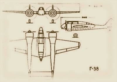
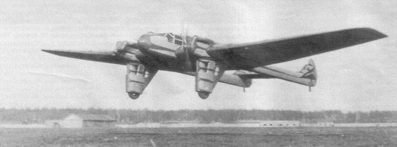
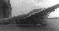
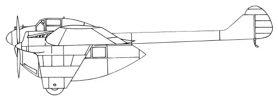
The G-38 was designed as a double-fuselage aircraft, of mixed construction, with great use of wood. Only the central gondola, intended for the crew, was made of metal. Control surfaces were fabric covered.
The wing was strengthened, allowing it to withstand heavy loads and even considering the possibility of hanging bombs, rockets and auxiliary fuel tanks on it. It was built in wood with a honeycomb structure and plywood covering.
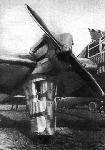
The 800 hp Gnôme – Rhône 14Krsd engines were located in the wing centerplane and were continued in the oval section tail cones, tapering towards the tail end, built on a wooden structure and covered in plywood.
The landing gear was of the conventional type with a tail skid. The main units retracted backwards, being stored inside the motor nacelles.
The central gondola housed a crew of three, with the navigator located in the bow and pilot and radio operator seated back to back.
The G-38 was designed with an armament of two ShVAK cannons and two ShKAS machine guns firing forwards, another two ShKAS machine guns operated by the navigator in the nose cabin and a last pair operated by the radio operator, defending the rear. There were also two AG-TB 40.8 mm grenade launchers. Under the central gondola bombs could be located on external supports.
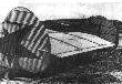
A scale model of the G-38 was built, which was blown in the TsAGI wind tunnel, showing the possibility of reaching a top speed of 550 km/h. The carpenters who worked on this model took such pains to polish it that the model was commonly called “the piano.”
In December 1934 the conceptual project of the “Light Cruiser” was finished. The new model surpassed in all its characteristics the similar models of AN Tupolev Mi-3 (ANT-21) , Mi-3D (ANT-21bis) and DIP (ANT-29).
MN Tukhachevsky, after getting acquainted with this project, declared the G-38 the “main object of aviation technique in the rearmament of the RKKA”. He especially demanded to increase the acceleration of development, stressing the state importance of the creation of this aircraft and promised, in case of successful flight tests, to recommend its creators to receive state awards and decorations. In two and a half months, a life-size model was finished, which was exhibited in a hangar at the Moscow Central Airfield, located in the Jodymka field. This mock-up was visited and analyzed by the commissar of heavy industry GK Ordzhonikidze, the head of the VVS Already. I. Alksnis , MN Tukhachevski and a significant number of senior Red Army officers.
Among the visitors was the test pilot Valeri Pavlovich Chkalov. After carefully reviewing the plane, he ended by saying to Grojovski:
“Excellent machine. Prepare it soon. The first flight is mine.”
The plans were quickly sent to the Leningrad Factory No.47, which operated under the Grokhovsky Institute. The G-38 prototype was nearly complete by the end of 1936. With the restructuring of the experimental institute and its change of subordination all the works were cancelled.
In 1937, after the firing squad of Marshal MN Tujachevski, a GUAP commission that visited the institute made the decision that the aeronautical construction at the Grojovski institute was not objective and aimed to destroy the aircraft under development, considered to have little prospect. In front of the workers of the institute, both the G-26 and the G-38 were transferred to one end of the factory airfield, doused with gasoline and burned.
G-38 Engines: 2 Gnôme-Rhône 14 krsd, 800 hp Wingspan: 13.4m Wing area: 32.0 m² Length: 8.8m Height: 2.9m Loaded weight: 4500 kg Wing loading: 160 kg/m² Power load: 2.8 kg/hp Speed at sea level: 550 km/h Landing speed: 125 km/h Armament: Two ShVAK cannons and six ShKAS machine guns Bomb load: 500 kg Accommodation: 3
The G-37 troop transport aircraft was obtained as a development of Grojovski’s ideas regarding means of air landing. On this occasion, the transporter plane could be used in different functions, including transporting troops using a special container that was fixed to the bottom of the center plane with capacity for 10-12 soldiers.
The project, originally known as ULK, acronym for Universalnoye Letayuche Krylo or Universal Flying Wing, was [Grojovski|PI Grojovski]] himself, but its design and projection were entrusted to the head of the Leningrad branch of Oskonbyuró IV Titov, production preparation was led by VF Rentel and execution by RM Kalinin.
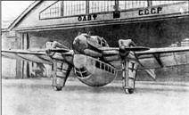
The Grojovski G-37 (Russian: Гроховский Г-37) was designed as a twin-engined, low-wing monoplane with a double tail cone. The structure was metal and the entire covering of the plane was made with corrugated metal.
The G-37’s wing came from a crashed Tupolev ANT-9. This wing was totally metal with a 4-spar structure and was made up of a centerplane and two consoles. Virtually the entire wingspan of the trailing edge of the consoles was taken up by the ailerons. After removing the ailerons, this wing presented an area of 80.97 m². A central gondola with the cockpit and flat bottom was fixed on the centerplane with a constant chord to allow the fixing of the detachable ventral cargo container.
In order to accommodate the ventral container, the G-37 featured a fixed landing gear with a long length of the landing gear faired in “trousers” with tunnel-type inlets for the oil and water radiators. The wheels were simple and there were no brakes. The suspension of the main landers was by rubber. In winter conditions, the replacement of the wheels with skis was foreseen.
Two M-17 liquid-cooled engines with a power of 680 takeoff hp and 500 nominal hp were selected as power plant, moving 3.15 m diameter fixed-pitch wooden propellers, also inherited from the Túpolev ANT-9. The motor mounts were fixed to the centerplane structure. The bonnets continued in the form of two parallel tail cones, ending in two medium-sized empennages. The empennages were metallic and were integrated into the structure of the cone. The rudders had aerodynamic compensators on the upper part and servo rudders or trimmers on the trailing edge.
The two tail cones were metal, with an oval section that tapered towards the tail and were located on the wing. In the lower rear part, the non-steerable landing skids were fixed and with suspensión was spring steel. Both empennages were joined by a constant chord stabilizer to which the elevator was attached. This stabilizer had a three-beam structure and was fixed to the empennages by means of 4 points in such a way that its angle of incidence could be modified on the ground. Originally the surface of this stabilizer was 10.5 m², but during the tests it was increased by 20%.
The fuel system consisted of tanks in the center of the plane with a capacity for 1000 kg of fuel.
The cockpit with capacity for 1-3 crew members was located in the central gondola, depending on the type of mission. In the bow was located the open cockpit of the gunner with the possibility of installing a pair of Degtiariov light machine guns on a swivel mount. Behind it was the closed cabin for two crew members located side by side. Behind this cabin was a small cargo or baggage compartment in which an additional fuel tank could be installed. The G-37 featured dual flight controls using cables and wires.
The fixing supports of the cabin in the center plane could be used to fix other types of containers or loads, and even to carry up to a ton of bombs.
Engineers VA Ryvkin, GS Avdieyev and spouses PS and AF Epishev also participated in the preparation of the landing cabin or container. All from OSOVIAJIM.
Already prior to the construction of the G-37, Grojovski and his collective had worked on the development of a cabin for 12 soldiers, individual containers for paratroopers, tested in a Tupolev TB-1 bomber, and a larger cabin for 17 soldiers, officially named KPS. -17 and known as “buffet”, which was tested on a TB-3.
The project planned various types of cabins depending on the aircraft’s mission, but only one was built, which was completed in Poplidki and attached to the aircraft in Moscow. This cabin was calculated to transport 10 passengers or 12 equipped soldiers or 10 wounded or four stretchers with a nurse.
Its construction was totally metal with corrugated metal covering and side windows. The length of the cabin was about 7 meters with the front hinged, forming an access opening to the right side. The soldiers or passengers were located on both sides on wooden benches, intertwining their legs due to the narrowness of the cabin.
This cabin featured a hatch in the forward part of the floor, which could be used to drop propaganda over enemy territory. This container could be dropped in flight, either due to an aircraft emergency or in the performance of a landing task over an area where it was impossible to land. The cabin descended with the help of a parachute 40 meters in diameter.
The G-37 was built in the winter of 1933-1934 at the Leningrad Factory No.47, which was subordinate to Grokhovsky ‘s OKB.
The pilot Valeri Pavlovich Chkalov was unable to fly due to the punishment imposed for destroying an airplane. For almost six months he had been forbidden to take flight and for him that had become a true torture. On May 7th he was at the civilian fleet airfield in Leningrad (formerly a hippodrome) and in an open hangar he saw the strange G-37 on the skin of which read “In the name of the Leningrad Komsomol”.
The G-37 was to be tested by AB Yumashiev on May 7, 1934, who had not arrived at the airfield at that time. Chkalov requested permission to run the G-37 around the runway. Knowing the punishment, they initially declined his request, but at his insistence they decided to authorize it, but warning him that he should only taxi.
Runway runs were run from end to end and Yumashiev was still missing, so Chkalov was cleared to make the first flight.
After takeoff the plane began to oscillate slowly, moving the tail up and down. This movement was increasing and it seemed that the flight would end in disaster, but Chkalov managed to land the plane almost at the end of the runway. After correcting the problem (a bad installation of the tail control cable) the factory tests developed quickly and without complications until June 1, 1934.
On June 12, 1934 Chkalov flew from Leningrad to Moscow, landing at Frunze Central Airfield (formerly Trotsky airfield located on the Khodimka field), where he received designation for further testing. There Grojovski and a group of Oskonbyuró workers were waiting for him. The aircraft was presented to GK Ordzhonikidze, MN Tukhachevski and Ya. I. Alksnis, making a positive impression. Above all, the visitors valued the high flight speed, much higher than that of the Tupolev R-6 that had begun to be produced in series.
During the transfer of the G-37, Chkalov without trying, managed to set an unofficial speed record for twin-engine aircraft. Covering the distance between Leningrad and Moscow in 2 hours and 15 minutes, the plane reached an average speed of 310 km/h. According to Chkalov, the plane could develop a higher speed after adjusting the engines correctly and replacing the old wooden propellers with new ones (these propellers, taken from ANT-9 planes, were exposed to the elements for more than three years, for which they lost between 15 and 20% its effectiveness.
Flight tests were supervised by PA Khrustalev.
Development testing of the G-37 took place during the winter of 1935. The aircraft showed excellent stability and response to controls. The centering and static moments of the tail units were maintained during the tests similar to those of the Túpolev ANT-9 and no vibrations or anomalies were observed in any of the flight regimes. Both the propulsion and fuel systems worked flawlessly throughout the testing period.
The flight characteristics of the G-37 with the cockpit hung under the fuselage deteriorated considerably. Top speed at sea level dropped to 235 km/h, while cruising speed at 2,500 meters was 250 km/h.
At the beginning of 1935 and at the request of the head of the VVS, Yakov Alksnis, new M-17 engines were installed in the G-37, with which performance improved significantly, reaching a maximum speed (without the container) of 375 km/h. These results opened up new prospects for the use of the G-37 as a postal or military reconnaissance aircraft.
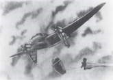
In the spring of 1935 the tests of use of the transport cabin were continued with drops of paratroopers through the lower hatch. Among the enthusiasts who took the plunge were Grojovski himself and several members of his collective.
Flight tests of the G-37 continued until November 1936 when the institute led by Grojovski was reorganized.
During testing it became clear that the idea had prospects for practical use, but the capacity of the ULK needed to be increased. Grojovski ‘s task force developed calculations for a version powered by modern M-34N engines and using a thinner, smooth-coated wing instead of the corrugated ANT-9. A model of this version, known as the G-37A, was tested in the VVA Zhukovski wind tunnel, yielding a possible top speed of over 400 km/h.
Unfortunately, these works could not be carried out due to the liquidation of the institute.
Despite the cancellation of the work on the G-37, the investigations carried out by Grojovski and his colleagues were not lost.
Between 1939 and 1940, in the OKB of SV Ilyushin, the conversion of the operational units of the DB-3 bomber would begin into a long-distance landing troop transport plane by adapting a D-20 metal cockpit created by AI Privalov under the fuselage. and designed to transport 10 skydivers.
DK-12 cabins for 12 soldiers were widely used during the Great Patriotic War attached to Il-4 (DB-3F) aircraft.
G-37 Powerplant: 2 × М-17, 680 hp at takeoff and 500 nominal hp Wingspan: 23.70 m Wing area: 84.00 m² Length: 15.20 m Height: 4.52 m Empty weight: 3075 kg Normal flight weight: 5950 kg Maximum takeoff weight: 6250 kg Fuel capacity: 650 kg Maximum speed at sea level: 240 km/h Maximum speed at altitude: 285 km/h Landing speed with maximum load: 90 km/h. Practical range: 1700 km ROC: 335 m/min Time to 1000 m: 3 min Time to 6000 m: 18 min Practical ceiling: 8050 m Accommodation: 1 – 3 Payload: 10 passengers, 12 soldiers or 1000 kg of cargo
Groen Brothers Aviation, Inc. (GBA) has developed a plan that can rapidly bring the gyrodyne into the modern age. Implementing this plan would enable the design, development, production and delivery of safe, fast, vertical takeoff and landing, long range high payload rotorcraft. These aircraft will have the ability to hover and will be economical, reliable and easy to maintain. This can be accomplished using a tiny fraction of the cost and time that would normally be necessary. Gyrodyne components and flight control systems can be incorporated into certain existing production high wing airplanes with only small modification to the airframe. The time and cost savings benefits of using an existing production airplane are possible because neither the airframe nor most of its systems will need to be designed, engineered, developed, structural loads measured, analyzed, tested, redesigned and engineered, tested again and then prepared for production. And, since the technology is simple, engineering risks are low. Groen Brothers Aviation has also developed proprietary mission adaptive rotor blade technology. This technology allows GBA’s rotor systems to be optimized for hover flight and then during transition from hover to forward flight it can change to be optimized for high speed. Load sharing between the rotor and the aircraft’s fixed wing adds to the high speed capability of GBA’s gyrodyne aircraft designs. Using an airplane that is already in production also means that the production plan, materials management system and massive supplier chain, quality assurance system, tooling, and production line are already in place and do not need to be designed, developed and paid for again, nor will there be a production learning curve to overcome. The only components that will need this development are the tip-jets (which have no moving parts), rotorblades, rotor head, mast and flight control system. Since the airframe is suspended from the rotor exactly from where it is suspended from its wing, in flight loads to the airframe should be virtually unchanged. This concept was successfully tested by Groen Brothers Aviation through modifying a Cessna Skymaster airplane. It’s two piston engines were removed. The forward engine was replaced with a Rolls-Royce model 250 gas turbine engine, and the aft engine was replaced with a large clam-shell cargo door. The wings were clipped and the existing twin boom tail was inverted to give rotor clearance. The rotor system from one of GBA’s Hawk 4 Gyroplanes was directly connected to the high wing attach points that were already carrying the Skymaster’s fuselage. This conversion, using minimal assets, took less than one year from first conception to first flight. This aircraft demonstrated its exceptional stability and ease of flight, characteristic of a well designed gyroplane. A technology demonstrator development of the Hawk 4 was announced in late 2000 as Hawk 6G with an expected first flight (prototype N9112A) in January 2001. The first flight was eventually made on 22 September 2001. Based around Cessna 337 fuselage with a single 335kW Rolls-Royce 250-B17F2 turboprop in the nose for propulsion, driving a FC9684C-6RX three-blade propeller, and a Rolls-Royce 250-C18 above the fuselage for rotation. The craft was fitted with an inverted Cessna 337 tailplanes and shortened wing with spoilers and two-blade rotor system from the Hawk 4. External fuel tanks are mounted at wingtips, and are modified Piper PA-24 Comanche wingtip units. Fuel capacity 416 litres. Estimated cruising speed was 209 to 241km/h, and a useful load of 907kg. Price was US$950.000 in 2003.
The 1995 Grob G-850 Strato 2C high-altitude and long-duration atmospheric/ stratospheric/ climatic research aircraft with a unique compound propulsion system using two turbocharged piston engines and two gas generators, was first flown March 1995. Featuring an extremely long span wing of composite construction, one aircraft was built in the 1990s, but was abandoned despite setting a world altitude record for piston engined aircraft on its last flight.
Engines: 2 x 300kW Teledyne Continental TSIOL-555 piston Max take-off weight: 13350 kg / 29432 lb Empty weight: 6650 kg / 14661 lb Wingspan: 56,50 m / 184 ft 9 in Length: 23,97 m / 75 ft 6 in Height: 7,76 m / 23 ft 12 in Wing area: 145.00 sq.m /1560.77 sq ft Cruise speed: 520 km/h / 323 mph Ceiling: 26000 m / 85300 ft Range: 18100 km / 11247 miles
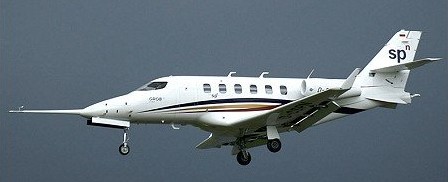
The Grob G-180 SPn (or spn) is a low-wing twin-engined corporate jet projected by Grob Aircraft in 2005. It can land on both paved surfaces and unimproved runway capability.
Engines: 2 x 1270kg Williams FJ44-3A turbofans Max take-off weight: 6300 kg / 13889 lb Wingspan: 14.86 m / 49 ft 9 in Length: 14.81 m / 49 ft 7 in Height: 5.12 m / 17 ft 10 in Cruise speed: 754 km/h / 469 mph Ceiling: 12497 m / 41000 ft Range: 3334 km / 2072 miles
The bases of this project go back to an idea presented by Fleet Senior Lieutenant II Golenischev-Kutuzov, who proposed to build a special hovercraft capable of carrying out torpedo attacks on enemy ships. Little by little the idea of the hovercraft was derived from a specialized seaplane. This idea of Golenischev-Kutuzov was presented to PRTV for its implementation.
The plane began to be designed and built in 1916 at the Shchetinin Society. Co – engineered by Mikhail Mikhailovich Shishmariov, who headed the construction department at the Shchetinin factory. Shishmariov developed the entire technical project for the new aircraft, while Grigorovich was in charge only of the general conception of the model and the general direction during the preparation of the plans and technical documentation.
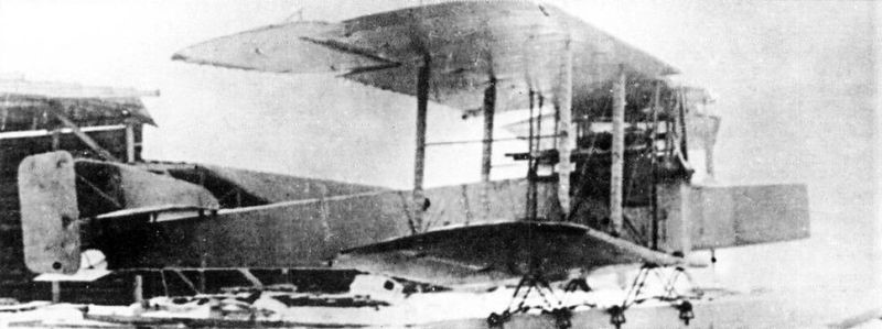
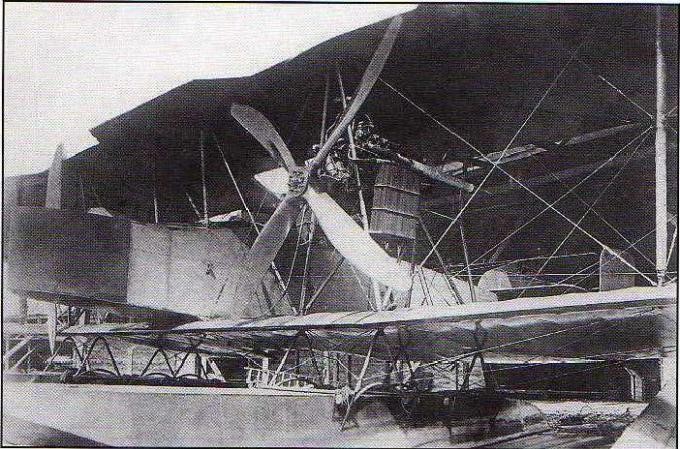
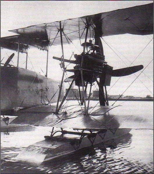
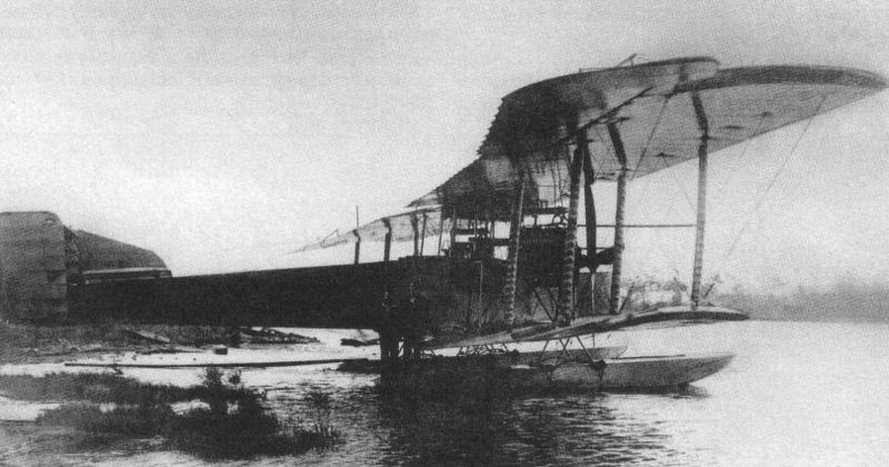
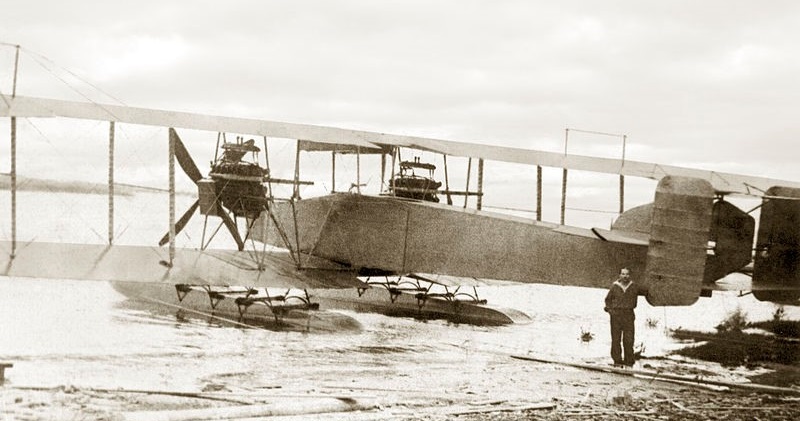
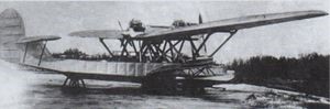
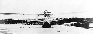
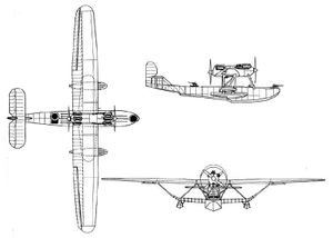
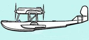
The GASN was designed as a huge twin-engine sesquiplane with a pair of floats and capable of carrying a 450-hp torpedo designed at the “Novi Lessner” factory in Petrograd. The power plant consisted of two 220 hp Renault engines located between both planes on steel tube supports and moving large four-blade propellers.
The initials GASN (Григорович/Шишмарев ГАСН) correspond to G idro Aeroplan S petsialnovo N aznachenia (Special Missions Hydroplane), although the model was also known as SON ( Samoliot O sobovo N aznachenia ) and in either of the two names it was considered to create an aircraft capable of carry and launch a naval torpedo, making this model the world’s first naval torpedo boat. We must add that this subject was considered highly secret, so in fleet documents references to the project are made as Type K.
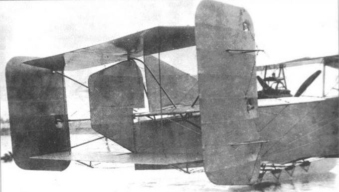
The floats had a traditional construction similar to that used for the hull of submarines at the time and were fixed to the lower wing by means of uprights in an inverted V made of steel tubes with rubber attachment points.
The fuselage had a rectangular cross section secured by cables and covered with fabric.
The tail was of the biplane type with three rudders and a small keel on the central empennage.
The large-span wing featured traditional wood-frame construction with fabric covering. The structure had three auxiliary spars to be able to fix the large ailerons. The shape in the plane of the wing was rectangular with a constant chord, but instead of being straight it presented a slight sagging.
The leading edge of the upper wing had indentations in the area of the propellers. The interplane supports were built with steel tubes on which they installed fabric-covered aerodynamic fairings and cable tensioners.
The GASN crew consisted of 3-4 people. In the bow area there was a position reinforced with sheets of plywood for an observer-gunner in charge of defending the forward hemisphere. Behind this position was the cockpit for two pilots and behind the wing box a third position for a gunner.
Even without completing the assembly of the first example, a request for the construction of 10 examples had been sent to Shchetinin.
The first flight of the prototype took place on August 24, 1917 in Petrograd under the leadership of Senior Lieutenant A. Ye. Gruzinov. The first tests showed that the GASN had good behaviour in the water and was easily controllable, but it was necessary to modify the trim and improve the response of the rudders. It was proposed to advance the engines, locate certain weights and increase the wing’s rake angle to advance the center of gravity of the airplane. It was also proposed to increase the surface of the rudders.
The GASN on Krestovsky Island in Saint Petersburg in 1920.
On September 24, during one of the flights, one of the floats was damaged, showing the need to reinforce its structure. After the repairs the plane began to fly again. These flights produced another series of problems, which is why the possibility of the Navy not continuing development and adapting the “Ilya Muromets” bomber or the Jioni twin-tailed plane for this role was considered.
The events of the revolution in Petrograd and the chaotic situation of the first years of the revolution prevented further development. Despite these factors, the GASN and an important set of construction elements of the started series of 10 copies were preserved intact, initially at the Shchetinin factory, which had changed its name to “Gamayún” and later at the “Krasni Liotchik” Factory.
The intention to continue the works would arrive in 1920. In that year Grigorovich traveled to Moscow and received an engineering post in Glavnoavia. His first task consisted of trying to continue the development of the projects stopped in the period 1917-1918. Grigorovich proposed to restore the work on the GASN torpedo bomber, knowing the state of conservation of the prototype and a good number of parts and components to assemble various aircraft of this type.
In November 1920 the GASN was made airworthy and the pilot LI Giks began carrying out the tests. Dmitri Pavolvich was on the shore supervising the process. On the 4th of that month, after long checks on the state of the engines, the mechanic Ozolin told Giks that the plane was ready for flight. The pilot stood in the cockpit and gave instructions to release the seaplane into the water.
During takeoff runs, tabs of fire began to come out of the exhaust pipes of one of the engines. Fearing a fire Giks decided to interrupt the test.
The engines were once more overhauled and the plane was finally cleared to take off, despite the fact that the weather conditions had deteriorated with a southerly wind that made take off difficult and the appearance of floating ice in the bay.
Steering the plane in the direction of Volni Island, Giks turned the plane upwind and took off. The plane was beginning to climb without difficulty when suddenly the engine on the right stopped working. The pilot turned for a landing near Krestovski Island. After gliding, the pilot managed to land and tried to steer the seaplane with a single engine. It was found that the seaplane’s rudder was ineffective and the aircraft only rotated around one axis. Giks directed the mechanic to go to the wing to try to compensate by sinking the float, but that didn’t help either. Waiting for help Giks switched off the engines. The plane began to drift freely.
The crew members removed the cushions from the seats, sprayed them with gasoline and lit them, throwing them near the plane as a signal for help, but help did not appear anyway.
For a whole day the plane drifted. At dawn the crew confirmed that they were about three kilometers from the shore and that the entire plane was surrounded by sheets of ice that made rescue difficult. Finally it was possible to bring the plane to the shore. The analysis of the accident showed that during the preparation of the flight, instead of oil, it was poured into the diluent tank.
With this the development came to an end.
GASN Power plant: 2 x Renault, 220 hp Upper plane wingspan: 28.0 m Wing area: 150.0 m² Length: 14.50m Payload: 1450kg Speed at sea level: 110-120 km/h Accommodation: 3 – 4 Armament: two machine guns Bombload: 450 kg torpedo or 480 kg of bombs
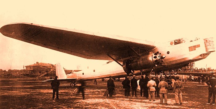
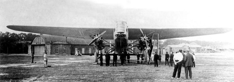
TB-5 the day of its first flight at Jodinka airfield. June 30, 1931
In the winter of 1929-1930 the OGPU leadership decided that it would be necessary to continue the chain of success of the TsKB -39 with a new bomber. In the spring of 1930 and again with great pressure on design and construction times, the requirements were delivered.
There is a version that alleges that the initiator of this idea was the then head of the TsKB-39 Ye. S. Paufler, who, seeing a high-wing aircraft with engines under the wings in a Farman promotion, decided that he should build something like that. All the builders refused except Grigorovich, who decided to take up the challenge.
Be it this way or not, the documents confirm that in the spring of 1930 and practically without the traditional approvals, the TsKB-39 was given the task of building a heavy bomber that was named Airplane-8 or TsKB-8. The VVS however refer to the model under the designation TB-5 (Russian: Григорович ТБ-5).
The deficit in aluminum production seems consistent that the air forces had opted for the creation of a model built from more affordable materials.
By the early 1930s, a new “Sháraga” or Special Technical Bureau (OTB) of the OGPU dedicated to the development of aircraft engines had appeared in the Soviet correctional system. Noted builders such as BS Stiechkin, NR Brilling, AA Bessonov were there.
This group was given the task of designing, testing and producing a 24-cylinder engine that was known as FED (an acronym for Félix Edmúndovich Dzerzhinski). This engine with 4-row distribution in X and central injection system, had to develop a power of 1,100 – 1,250 hp at an altitude of 3,000 meters and its construction was directed by AA Bessonov. These values were considerable for the time.
The FED was conceived as the power plant for the new TB-5 bomber and its installation was planned in two variants: on the wing leading edge or in gondolas fixed to the wing intrados. Different situations led to the FED not being available at the established time, so the TB-5 had to be equipped with 4 Gnôme-Rhône 9Aq engines , a licensed copy of the excellent British Bristol Jupiter VI engine later built under license in the Zaparozhie Factory No.29 as M-22. The engines were located in tandem under each wing console. Despite the fact that the total power was almost similar to that calculated, the new drive installation had much more frontal resistance and the efficiency of the propeller was reduced by the tandem configuration, which had a negative impact on performance.
Practically all the personnel of the TsKB and a large part of the personnel of the VR Menzhinski Factory No.39 in Khodinka were mobilized for the work on TB-5, where Paufler’s “Sháraga” would be transferred from the Butirka prison.
Airplane-8 was built in just one year, which was record time for such a large and complex aircraft. Grigorovich in the same period, in parallel, worked on the IZ fighter. The appearance of both models in May 1931 (and the resounding success of the I-5) practically caused Grigorovich to receive amnesty.
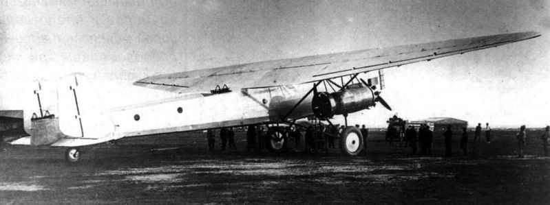
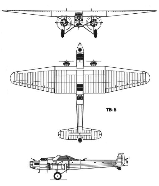
The TB-5 was designed as a high-wing bomber with a double tail unit. Its construction was mixed, with little use of aluminum, a metal short in the USSR of those years.
The spacious fuselage featured a skeletal structure constructed from fabric-covered welded steel tubes. For ground transportation, the fuselage could be divided into three sections: the forward section to the wing trailing edge, the intermediate section to the beginning of the stabilizer, and the tail section.
The TB-5 wing featured a three-spar structure and constant rib pitch. The stringers were built with special profiles made of duralumin and tubes. The ribs were formed by stamping. The construction of the wing was quite complex, especially when it came to covering the fabric.
The airfoil selected was the R-II with 18% in the midplane area and 12% in the extremes. The wing had some small bracing supports that also helped to give the necessary rigidity to the power plant.
The tail was built on the basis of a fabric-covered aluminum frame. The horizontal plane presented a second, thinner unit, located at a greater height and called “stabiliron”, creating a kind of biplane box. Its function was to decrease the force on the joystick during landing operations and trim changes.
In the TB-5, on each side of the fuselage, under the wing, two 480 hp Gnôme-Rhône 9Aq engines were installed in tandem, so that they moved a propeller with two wooden blades in a driving configuration and another in a driving configuration. This engine would later be built under license under the designation M-22. In order to improve cooling, the rear engine was fitted with a Townend ring around the cylinder head.
The projected bomb load (with the use of the FED engines reached 2,500 kg) was located in an interior hold in the fuselage. DER-18 supports were located on the sides of this hold, allowing the crew to move freely inside the aircraft.
Defensive armament consisted of three TUR-5 turrets with paired Degtyaryov light machine guns for aircraft. The first of these turrets was located above the forward navigator’s position, just in front of the cockpit; the second just behind the wing and the third in the tail section of the fuselage. Apart from these positions in the bow there was a mobile firing tower, developed in the armament section under the direction of AV Nadashkievich. This can be considered the first Soviet attempt to obtain a remotely operated turret using mechanical and electrical controls.
This tower was built in the form of a cylindrical tank that rotated around its vertical axis. In the front part it had a slot that allowed the vertical displacement of the two machine guns. The horizontal movement of the machine guns was ensured by the rotation of the tower. The gunner was located inside the tower and if necessary, could leave it using a rear door towards the nose of the aircraft. For the first time in the USSR two PV-1 machine guns were installed here, built on the basis of the infantry Maxim, but using air cooling instead of water. For the first time, uninterruptible belt feeding was also used.
The rotation of the tower was carried out by means of an electrical system and the vertical movement of the machine gun was carried out by the shooter, located in a small seat.
Pilot and co-pilot were located in a closed cabin, with seats side by side. The crew of the TB-5 had some facilities that could be considered a novelty for the time: a toilet and four hammocks for resting.
Grigorovich TB-5 shortly before starting his first flight.
In the early summer of 1931 the TB-5 was first brought out onto the airfield. After engine tests and a few runs, the decision was made to allow the flight. On June 30, 1931, test pilot B. Buxgolts made the first test flight over Jodinka airfield.
After landing, Buxgolts came down from the cabin smiling and said:
“Stability in the air is good. Ease of control excellent. Very little pressure on the rudders.”
By July 20, the plane had made four successful flights. With a weight of 11,200 kg and a fuel capacity of 1,850 kg, it had managed to cover a distance of 1,100 km during 6.7 hours of flight with an average speed of 162 km/h and a ceiling of 3,000 meters. Range with maximum fuel load of 2,410 kg and takeoff weight of 12,060 kg (including 500 kg of bombs) was 2,100 km. The maximum speed recorded was 180 km/h, the ceiling was 3,500 meters and the take-off run was about 400-420 meters.
The TB-5 during the development of the tests.
The performance obtained was not high, especially when compared to the Tupolev TB-3 bomber that had already been flying for a few months. The main cause of these results was the powertrain. The propellers used were more suitable for a fighter than for a bomber of that size. To make matters worse the rear propeller had to be shortened so that it could operate under the wing.
Despite these difficulties, the TB-5 presented a not insignificant set of advantages, among which stood out a better distribution of defensive weapons, better distribution of the bomb load on the plane, smaller dimensions and weights, much lower cost and simpler construction. The group of builders did not lose hope of being able to count on the promised FED engines, with which performance should be increased significantly. It should be noted that by the summer of 1931, Factory No.24 had 12 engines of this type in production and had aggregates and components for another 10 units.
Front view of the Grigorovich TB-5 bomber.
All these possibilities were evaluated and finally on July 25, 1931 the Labor and Defense Council (STO) asked the Pan-Soviet Aviation Union to prepare the conditions to produce six TB-5 bombers (one as a prototype of the series and the other 5 to perform military operation tests). Almost in parallel with this decision, these specimens were included in the plans for the formation of the new bomber squadrons for 1932.
The head of the VVS PI Baranov considered that, due to the delay presented by the FED engines, it was advisable to postpone the manufacture of the TB-5 copies for the year 1932 and he sent a request with these reasons to the United Council of the Economy of the USSR (VSNJ according to the initials of Vsiesoyuzni Soviet Narodnovo Jozyaistva). However, the chairman of the Council of People’s Commissars (SNK) VM Molotov had other ideas, so he ignored Baranov’s request and instead requested to take the necessary measures to speed up the construction of the series. According to M. Maslov the reasons for this decision could be of a political nature. The TB-5 bomber had been created within the OGPU and just a few days before, on July 6, 1931, this organization had given Stalin a demonstration of its achievements. There he was shown the I-5 fighter, the R-5 reconnaissance aircraft, the TSh-1 attack aircraft, the TB-5 bomber and the modern IZ gun-wielding fighter. Stalin was widely pleased and hinted that the OGPU leadership seemed to have succeeded in finding the most productive formula in aeronautical development. As a collateral consequence of this presentation, on August 27, 1931 the TsKB and the TsAGI would be unified under Czech control in the TsKB-TsAGI organization headed by Ye. S. Paufler.
During this time the TB-5 had received a significant group of improvements. In the month of June 1931, work was done on the structural reinforcement and the fixing system of the engines. The cockpits were fitted with upper access hatches, glazing was introduced in the midplane trailing edge area, the Townend ring was removed from the rear engines.
During the winter of 1931-1932 the bomber was prepared to operate with skis and several flights were made to analyze its behaviour. The design group was working on improving the conditions for installing the still awaited FED engines, but other variants of installing engines on the leading edge of the wing were analyzed. Works on this configuration were led by SA Kochierigin. Scale models with this configuration were tested in the TsAGI wind tunnel.
During this stage, other aeronautical constructors such as BI Cheranovski, VP Yatsenko and AN Refaeliants worked on the plane.
Unfortunately, the construction of the series could not be carried out, mainly because Factory No.39 was overloaded with the production of several experimental models.
The TB-5 flights continued and Soviet pilot MM Gromov would participate in them.
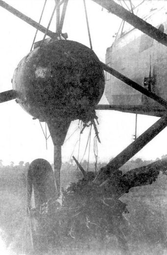
During one of the days of May 1932 and during a flight at a height of 800 meters a strong vibration began. The cause was that the left rear engine detached from the mounting bracket and the propeller broke the fuselage and embedded itself in a wooden bomb mock-up. The fuel caught fire.
Gromov ordered to shut off the fuel supply to the engines and began to glide with dives over the left wing to try to put out the fire. Eventually this was achieved and the pilot made a forced landing at Factory No.22 airfield in Fili. Only at this moment did they become aware that when the flames intensified the engineer AV Chesalov, who was in the wing area, had parachuted down to land without difficulty.
Condition of the left engine of the TB-5 after the accident of MM Gromov.
After this mishap, the TB-5 remained in Fili until December, without repairs being attempted. Grigorovich had switched to the development of fighters.
At the end of 1932, after verifying that the manufacture of the Túpolev TB-J bomber (military version of the ANT-14) was even more complicated than those of the TB-3, it was decided to return to the subject of the TB-5.
To assess the possibility of re-establishing the TB-5, a commission was created led by the representative of the TsAGI VN Chernishevich, who worked on December 1, 1932. As expected, the competing aircraft was harshly criticized: the aircraft was valued as overweight, with poor motor installation and design problems. On the other hand, the TB-5 had had its engines, part of the flight instruments, and weapons disassembled, and it was estimated that to give the bomber full flight capacity again, it would be necessary to invest 75 or 100 thousand rubles.
The commission considered that to improve the bomber it would be necessary to reinstall the engines on the wings, which would guarantee an increase in speed, which would reach 190-200 km and a ceiling of 4000 m, but the cost of the modifications would amount to 200 thousand rubles.
Incredibly, despite these assessments, it was decided to restore it with the proposed modifications, for which it would be returned to Factory No.39. A short time later, at a meeting of the VVS management, it was recognized that even with the modifications, the benefits of the TB-5 did not satisfy the requirements of the moment.
In the month of February 1933 the head of the GUAP Baranov instructed:
“The plane disarm it. Works on him stop them.”
With this it all ended. TB-5 was not restored and its remains were handed over to the TsAGI structural resistance department. The Tupolev TB-J also did not see the light of day, as by the end of 1933 the specifications for bombers had grown considerably.
On the basis of the TB-5 in 1931 Chertverikov developed the reconnaissance flying boat MDR-3 or TsKB-11, which kept the design of the wing, tail and structural elements of the bomber. Finally, this design would not be produced either.
TB-5 Powerplant: 2 × 480 hp M-22 ( Bristol Jupiter VI Wingspan: 31.00m Wing area: 150.00 m² Length: 22.10m Height: 5.02m Empty weight: 7483 kg Normal takeoff weight: 12535 kg Wing loading: 83.5 kg/ m² Power Load: 7.0kg/hp Fuel + lubricant capacity: 3300 kg Top speed: 200km/h Cruising speed: 182km/h Range: 2100 km Ceiling: 3500 m Accommodation: 5 – 7 Armament: 3 x TUR-5 type turrets with paired Degtyaryov light machine guns / 1 x pair of PV-1 machine guns Bombload: 1000 kg
In September 1927, when the assembly of the first prototype of the open sea explorer ROM-1 was finished, it was decided to give the green light to the construction of a second prototype, which received the designation ROM-2 or MR-3bis (Russian: Григорович РОМ-2 (МР-3БИС)).
Already in mid-1927 the Aviatrust leadership was convinced that the work of the OMOS naval department in Leningrad was not bearing the expected results, so all experimental work had to be concentrated in the capital.
In September 1927 the decision was made to dissolve the OMOS TsKB and transfer all its specialists to Moscow, placing them in the facilities of Factory No.22 in Fili. About 200 workers were transferred from Leningrad to Moscow, including 44 builders. The organization in the new location was renamed OPO-3 (acronym for O pytni P roizvodsvenni O tdiel – 3 or Experimental Productive Department – 3). In practice, this transfer process lasted until the first quarter of 1928. In the documents of this period related to the start of the activity of the EPO-3 it can be seen that the financial situation was destabilized and losses of state assets were recorded.
On 27 June 1928 the president of the Aviotrust , MG Uryvayev, called a meeting in the building of the EPO-3 in which the director of the factory No.2 FS Malakhov participated PD Samsonov as a representative of the OPO-3 (Grigorovich was in Sevastopol in the process of continuing the ROM-1 tests), VI Nikitin as replacement for the head of the OPO. The meeting basically touched on the problems of the new situation. It was reported that in Moscow the acceptance of the Leningradense group had not taken place and that the interrelation with the factory was progressing with difficulty. The facilities provided for the work were small and insufficient for the staff, their repair extended over time. The phone connection had only been running for a month and a half.
The supply of materials was defined as lousy, the workers assigned by the factory were all of low qualification, the salary for the members of the OPO-3 was lower than that of the rest of the factory workers (this was explainable because despite that the OPO-3 was considered a section of Factory No.22 was not subordinate to its technical line). It was also said that for housing issues of the 13 employees received, half had already left the department (later, the abandonment of the OPO-3 by specialists and collaborators would increase in such a way that by the end of 1928 only 50% remained of transferred personnel).
Under these conditions, ROM-2 was built.
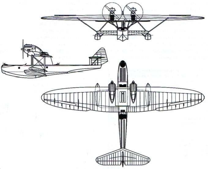
Originally the main difference between the ROM-1 and ROM-2 was the installation in the latter of two German BMW-VI 500/680 hp engines located separately on the wing, but during the construction process important modifications were made. In the work records of the OPO-3 it is stated that in Factory No.22 a new hull and elliptical wings were built for this hydrofoil.
The upper wing kept its wooden construction, but its plan view showed an almost elliptical shape with ailerons of increased area and a surface area greater than 5 m². The leading edge had less curvature than the trailing edge. On this occasion, the extrados of the centroplane featured a corrugated aluminum coating. The wing consoles featured a double stringer structure with plywood covering from the leading edge to the position of the second stringer. From then on, the covering was made of fabric. The ailerons and the tail section kept the fabric covering.
The lower metallic wing was little different from the original ROM-1, but the underwing floats lost their reef and were fixed with small piles to the wingtips.
The hull was lowered by 1.5 meter. The contours of the ROM-2 were quite different and were characterized by increased transverse sagging in the keel area with the sides concave on the bottom, which ensured a smoother landing, especially in swell. In the lower zone, near the recess, the coating reached 1.5 mm. In the rest of the helmet 1 – 1.2 mm.
The fuel system was modified. Three fuel tanks with a total capacity of 810 liters were installed in the center of the hull. A fourth tank with a capacity of 310 liters was installed in the center plane. During the tests, the engines used 3.25 and 3.5 metre propellers interchangeably.
The ROM-2 crew was maintained with 4 people and its defensive armament consisted of two points of fire operating paired Lewis or DA machine guns. A TUR-6 turret was mounted in the fore area and a TUR-5 in the rear position. Small bombs could be placed on the gunwales as on the Dornier Wal. Larger calibre pumps could be installed under the lower wing. The total capacity of ropes reached 600 kg. As special equipment highlights the installation of a Kodak camera in the rear cabin and a tank with drinking water for long flights.
An anchor was located in the bow, which during the flight was fixed to the upper front deck.
Another distinctive feature of the ROM-2 was the ability to be dismembered in such a way that the hydrofoil could be moved overland using four rail platforms.
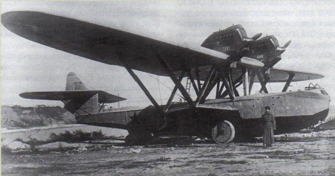
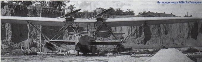
ROM-2 in Taganrog
The ROM-2 was to be projected to fly for 5 hours covering a radius of 500 km. Its construction began in Leningrad at the then-renamed Factory No.23 (Formerly GAZ No.3 “Krasni Liotchik”), but was soon moved to Moscow, to the collective’s new location at Factory No.22 in Fili.
The ROM-2 left the OPO-3 workshops at the beginning of July 1929, but only a month and a half later it would be fully ready. At the end of September the prototype was shipped by rail to Sevastopol, where it was assembled and prepared for flights. There it was found that the hydrofoil showed an increase of 690 kg in relation to the projected data.
The date of the first flight of ROM-2 is not exactly known, but it must have occurred around October 1929. As a test pilot, S. Rybalchuk, who had previously flown the unsuccessful ROM-1, was selected.
There is evidence that the short testing period was characterized by minor problems and breakages. On November 6, during the launching process, the lower right wing and the stabilization float broke. On the 29th of that month another accident occurred in Sevastopol, near the Konstantinov battery. That day at 1:45 am Rybalchuk took off and landed with quite rough seas. During the third landing the plane entered facing a wave and as a result several construction elements were damaged.
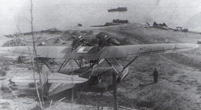
ROM-2 during the tests in Sevastopol.
The report that was produced highlighted the successful hull design, the spaciousness of the cabin and the good performance in takeoff over the sea. The stabilization float scheme was considered unsuccessful and the lack of rigidity in certain elements of the construction was highlighted. The radius of action of 445 km, maximum speed and manoeuvrability in the air were also highlighted as negative.
In Rybalchuk’s report can be found: “The performance of the ROM-2 can be considered somewhat superior in relation to the ROM-1, especially in relation to maximum speed and control. The overall performance rating can be considered below average. The machine remains heavy and in this configuration it has no prospects. “
As a conclusion in December 1929 it was considered that the ROM-2 2BMW6 was not ready to enter service with the VVS. It was decided to return it to the factory to repair the defects and deliver it for retesting before August 15, 1930. It was recommended to lengthen the nose to improve the behaviour on the water, review the design of the floats, locate the engines towards the depth of the wing and advance the location of the pilots.
Once at the factory, they worked on repairing the prototype. The hull was shortened by 0.20 meters, the engines were raised on the wing, being located on some N-type structures. Baptized ROM-2bis, the new variant, according to the opinion of military specialists, had nothing to offer either.
Despite the fact that by the end of 1929 in the OPO-3 all the detailed plans for the series production of the ROM-2 had been completed and that Factory No.22 had prepared to take on a small series of 22 copies, for reasons not very clear this production would not be carried out. Work on ROM-2 was abandoned and the project for an improved model, known as ROM-3, was never completed.
Grigorovich ROM-2 Engines: 2 x 500/680 hp BMW VI Wingspan: 26.80 m Wing area: 108.20 m² Length: 17.40 m Empty weight: 4150 kg Normal takeoff weight: 6587 kg Oil weight: 90 kg Total load capacity: 2437 kg Wing loading: 61.0 kg / m² Power load: 4.9 kg / hp Maximum speed at sea level: 180 km / h Maximum speed at 3000 m: 163 km / h Landing speed: 95 km / h ROC: 143 m / min Turn time: 50s Range: 900 km Endurance: 5 h Service ceiling: 4500 m Time to 1000 m: 7.0 min Time 2000 m: 14 min Time 3000 m: 22 min Practical range: 900 km Landing run: 170 m Take-off run: 250 m Accommodation: 4 Armament: 3 x Lewis or DA machine guns in turrets TUR-6 (forward) and TUR-5 (in the rear fuselage). Bombload: 600 kg
On June 17, 1925, the Scientific Committee of the Directorate of the VVS (UVVS) approved the technical task for the development of an open sea exploration airplane (ROM according to the initials of Razviedchik Otkrytovo Morya) with two Lorraine-Dietrich engines of 450 hp. Almost in parallel OMOS was tasked with creating a hydrofoil to cover this request.
Development of the Grigorovich ROM-1 (in Russian: Григорович РОМ-1) commenced in the summer of 1925. The aircraft was ordered during Summer 1925, the task was considered of high priority. According to the TZ, the hull had to be all metal (aluminum alloy), the wing – wooden. V.B.Shavrov was responsible for hull design, P.D.Samsonov – for wing and powerplant. The hull layout was chosen as simple as possible to avoid complicated procedures.
The ROM owes its name to the initials of Razviedchik Otkrytovo Morya or Open Sea Explorer, but the company internally called it MR-3 (Morskoi Razviedchik – 3) and apparently the Navy also called them MDR-1 (Mosrkoi Dalni Razviedchik – 1), so in literature it is sometimes named in these ways. Shavrov also used the name MR-3 to refer to Grigorovich’s MR-5 model, which has contributed to some confusion, although today there is consensus that this was an error by the author.
The ROM-1 (ROM = Razviedchik Otkrytovo Morya [Open Sea Reconnaissance]) was a long range maritime reconnaissance sesquiplane flying boat with two engines installed in a tandem nacelle, supported on struts over the hull. The hull was made from aluminum and the wings were made of wood, attached to the sides of the engine nacelle. The water-tight lower wings, attached to the sides of the hull, were installed slightly above the waterline and carried two floats on their tips. The ‘wing box’ included 20 struts. Thickness of the walls was from 1.0mm above the waterline and 1.5…2.0mm below. The tail surfaces had aluminum alloy frames with fabric covering.
The upper wing, built in wood, had a span of 27 meters with a total area of 86.6 m². The two stringers of the upper wing had a trunk-like structure. Initially each of them had a single thickness of 100 mm throughout the span, but later pairs of 60 mm thick were installed. The wing nerves were skeletal in type. In the upper part of the wing from the leading edge to the second spar the covering was plywood covered with fabric and from there only fabric. The upper wing had a Gettingen-426 profile, but a thicker Gettingen-420 profile was used in the area where the supports were attached, so when looking at the model from the front, the variation in wing thickness could be clearly appreciated, which widened towards the center of each half plane.
The lower plane was made entirely of aluminum and, like the helmet, was covered in waterproof coated fabric. The stabilization floats were located in the external section of the intrados, which had a semicircular section in the upper part and a configuration of a reent in its lower part. Fixing to the wing was done by eight small steel supports.
Originally all the joints were caulked with layers of fabric covered with anticorrosive or tar, but here a mistake was made: the tightness was achieved but the thickness of the layers at the seams tried against the finish. Soon all this work would be scrapped and the joints would be covered with waterproof tape, giving the finish more aesthetics.
The bracing between both planes was achieved by means of 20 diagonal supports and two stiffness frames, which was directly reflected in the increased weight of the structure. The inner interalar supports were made of aerodynamically shaped aluminum tubes but the outer ones were made of rectangular profiles.
Samsonov proposed the installation of two 450 hp Lorraine-Dietrich engines, located in tandem and opposite on the centroplane, so that they moved a traction propeller and an impeller. The need to move the engines forward to improve the c of g resulted in the need to locate two steel supports located forward on the hull, just in front of the cockpit.
The ROM-1 crew consisted of four people. In the bow area a gunner was installed operating a pair of Lewis machine guns in a TUR-4 turret with a Herts collimator. Two crew members: pilot and mechanic, sat side by side in an open cockpit, located in front of the wing leading edge and protected by a small windshield. In the rear section of the fuselage, just behind the propeller, there was another defensive position covered by the fourth crew member, operating a pair of machine guns in a TUR-5 turret, which covered the rear hemisphere. A number of bombs could be attached to both sides on Sbr-8 brackets and bomb aiming device in the nose cockpit.
The centering of the hydrofoil was the cause of the biggest headaches. To achieve good stability it was necessary to position the engines well forward, increasing the length of the driving nacelles and installing two new interplane supports not conceived in the original project, which added a little more weight to the construction. Despite this, the rear centering was still outside the permitted limits. This had to be corrected by the crew before take-off by distributing cargo and fuel.
In the process of developing the ROM there were important variations in the request of the military. Despite having approved the project as a reconnaissance aircraft, on May 31, 1927, the Aviatrust requested the possibility of considering the installation of a Type 1915 450 kg torpedo. Grigorovich objected that this installation would bring important changes in the project and the need to use more powerful engines, but finally he would develop a conceptual project with this configuration that is known as MT-1 (MM-3).
Built at GAZ No.3 “Krasni Liotchik” of Leningrad, in order to build the metal hull, it was necessary to prepare the production in Leningrad of the aluminum sheets, pipes and rivets, since the AGOS profiles, which were already being produced, could not be used. In western countries these elements were already manufactured in large quantities but Soviet finances in the 1920s could not afford such expenditures.
On the other hand, a new need also arose: to develop the structural elements of the hydrofoil hull, designed from angles with profiles of 1.5 – 2 mm thick and 800 mm wide. The cross section of the hull had the shape of a pentagon all along with the tip pointing downwards, since a certain angle (12º) was conceived in the keel area. The majority use of straight lines with simplified contours was maintained. The recess had a height of 150 mm and an inclination of up to 45º.
On September 15, 1927, the management of the “Krasni Liotchik” factory declared that the ROM was practically ready, leaving only to stretch the fabric covers and complete the equipment. Already abroad, the hydrofoil was assembled and painted and on September 27 the Aviatrust technical committee gave the green light to the delivery for the flight tests. In parallel the OMOS TsKB was tasked with starting the construction of a second prototype. From this moment on, the first prototype was called ROM-1 (MR-3) and the new prototype ROM-2 (MR-3bis).
In the spring of 1927 static tests were carried out, which showed that in general the construction of the hydrofoil could be characterized as resistant. The wing, however, showed a deflection of 0.3 meters under normal overloads and up to 1.5 meters before breaking, prompting the replacement of the 100mm spars with a 60mm pair. The center plane section was also reinforced. Unfortunately these measures increased the weight of the aircraft by about 600 kg. The ROM-1 suffered from same problem as some other aircraft of D.P.Grigorovich – too rear CG location. To fix the problem engines, fuel tanks and payload were moved forward.
The prototype ROM-1 built at GAZ-3 first flew in the autumn of 1927. The first flights were made in Leningrad, in the immediate vicinity of the Grebni test station.
At conclusion of the flight test pilot L. Giks wrote: “The take-off from the water took place at a speed of 97 km / h with an ascent speed of 3 meters per second. The flight took place at an altitude of 400 meters. Gliding at a speed of 110 km / h with engines off was stable. The speed recorded on landing was 85 km / h. During the circle flight the handling was normal. The aircraft responds well to the ailerons, but the rudder surface is insufficient. He responded better in the height shot. Backward centering is felt and the plane finds it difficult to dive. In general, the aircraft is heavy at the controls, which can be explained by the low speed with a very large take-off weight. “
The tests of the model carried out in Leningrad until November 1927 were characterized by the absence of a defined system or program. Grigorovich felt quite uneasy during those days, he took the project with a certain coldness and did not even show up to the tests, something unusual for him. The OMOS had received the order to leave Leningrad and move to Moscow to locate in a factory in Fili where the OPO-3 of the TsKB would be created.
On November 21, 1927, with the beginning of the winter frosts, Dmitri Pavlovich ordered the aircraft to be dismantled, moved to the commander’s airfield, packed the parts in boxes, and shipped to Sevastopol.
At the end of November 1927 the ROM-1 was sent to Sevastopol, where the flight tests were continued. On February 24, pilot Giks reported: “Take-off takes place at speeds of 90 – 95 km / h. During the flight you feel pressure on the legs, but not great. I reached the height of 3200 m. At speeds between 80 – 90 km / h the landing is excellent. With a load of 1500 km the maximum speed is 158 – 162 km / h. Ailerons are not very effective. “
In June 1928 it was decided to send the ROM-1 to Taganrog with the aim of making a number of improvements there. Grigorovich arrived in Sevastopol, who was to continue with Giks towards Taganrog, but none of this happened. A couple of months later, upon arriving in Moscow, Grigorovich was arrested.
The work on ROM-1 was continued under the direction of P. D. Samsonov, as representative of the OPO-3. As of August 20, 1928, a series of modifications were made that included the installation of new 2.96 m diameter propellers obtained from a Farman, internal changes in the cabin, addition of 900 × 200 mm wheels (from a Vickers Vernon), which could be installed to facilitate the entry and exit of water, among others.
In Sevastopol the flights were carried out by the pilot S. T. Rybalchuk. After the changes, a certain number of flights were made in which the flight characteristics were not fixed. In the final report, written in the fall of 1928, the pilot wrote: “The excess weight of the construction does not allow to load the total capacity of fuel for prolonged flights nor the completion of the armament. The weak Lorraine engines of only 450 hp are not sufficient for normal piloting of the airplane at maximum payload. I consider that the ROM-1 in the current state cannot be used in the proposed mission. “
The situation became doubtful, but the opinion had been created that the ROM-1 could not be used as a military model, so it was simply left in the open awaiting decisions from the commanders.
Shortly before the 1929 flying season they remembered ROM-1 again. The prototype was admitted to Factory No.31 in Taganrog for review. Mechanical engineer K. N. Ganulich wrote in the report: “As a result of the plane being in the open all autumn, the wooden wings have been damaged in such a way that they need to be repaired. The entire interior surface has been filled with water, the coating has become moldy, and the plywood layers have separated at the leading edge. The worst condition is the leading edge and ailerons. The helmet is in good condition. The coating lacquer is fine. “
The ROM-1 repairs were carried out between April and mid-May 1929. The hydrofoil was again flown and sent to Sevastopol. On June 17, 1929, the assistant to the head of the VVS RKKA Ya. I. Alksnis gave the order to conduct state testing of the ROM-1, ROM-2 and MR-5 models.
The tests began in Sevastopol on July 2, 1929. The first attempts, carried out in Golandia Bay, showed that with a center of 30.4% the hydrofoil did not lift the bow. They were forced to return to a base in Najimov Bay, where a person moved into the rear cabin and a 40 kg dead weight was added there. With this, it was possible to move the centering to 35% and it was possible to take off without difficulties, but warming of the engines was appreciated.
At night, when the temperature dropped, Rybalchuk managed to make a flight in which a height of 3470 meters was set. The next day new radiators taken from a Dornier Wal were installed and several flights were made until August 2. A total of 84 flights were executed in ROM-1.
In preparing the report Naval Aviation NII engineer Korovin wrote: “Poor visibility from the cockpit, hard controls, sensitive pedal pressure on the right leg, complex starting system. Shallow cabin, high deck. Pilots cannot exchange positions in flight. “
It was also found that, with a load of 1305 kg in calm sea, take-off was impossible. The tests had to be carried out with loads of 1135 kg.
On September 19, 1929, a commission, made up of specialists from the NII under the direction of the head of the Black Sea VVS Lavrov, defined that the ROM-1 could only be used in pilot training tasks or as a transition model to operations.
The withdrawal of the ROM-1, as late as 1928, from flight tests was a terrible blow to Grigorovich’s reputation. The extremists accused him of being a saboteur and wasting the valuable resources of the Soviet state on experiments. On September 1, 1928, Grigorovich was removed from his position and arrested under the accusation of developing anti-Soviet activities within the famous Prompartia case.
Only after the failure of the ROM-1 did Grigorovich come to understand the importance of accuracy in aerodynamic calculations, the resistance of materials and the details of operation. And despite the fact that the evolution of global hydroaviation passed before his eyes and to some extent with his participation, Grigorovich unfortunately drew few useful conclusions for himself from this process.
Grigorovich ROM-1 Engines: 2 × Lorraine-Dietrich 12E W-12, 340 kW (450 hp) each Crew: 4 Length: 16.0 m (52 ft 6 in) Wingspan: 28.0 m (91 ft 10 in) Wing area: 104.6 m2 (1,126 sq ft) Empty weight: 4,518 kg (9,960 lb) Max takeoff weight: 5,830 kg (12,853 lb) Fuel weight: 775 kg Oil weight: 185 kg Total load capacity: 1312 kg Maximum speed: 165 km/h (103 mph, 89 kn) Cruise: 132 km/h Range: 800 km (500 mi, 430 nmi) Endurance: 5 hours Service ceiling: 3,470 m (11,380 ft) Time to 1,000 m (3,281 ft): 10 minutes 6 seconds Time to 2000 m: 25.3 min Time to 3000 m: 54 min Takeoff Speed: 118 km/h Landing Speed: 85 km/h Landing Roll: 13 sec Takeoff Roll: 25 sec Turn time: 80 sec Wing loading: 56.0 kg/m2 (11.5 lb/sq ft) Armament: 4 x 7.62 mm (0.300 in) DA machine guns Crew: 4
The Grigorovich E-2, or DG-55 (Russian Григорович Э-2, ДГ-55), was a two-seat, twin-engined, low-wing, prototype sport aircraft of Soviet origin.
Inspired by the de Havilland DH.88 Comet racer which had won the MacRobertson Air Race in 1934, the Grigorovich OKB began work on a similar aircraft. Like the DH.88, the Russian “Kometa” was a highly streamlined conventional low-wing monoplane with twin engines forward of retractable main undercarriage in nacelles under each wing. Built of wood, it also featured an enclosed cockpit and landing flaps.
Intended to be a lightweight, high-speed sport aircraft the DG-55, later designated the E-2, was slightly smaller than the DH.88 and with less powerful engines, using the 120 hp (89 kW) Cirrus Hermes.
Only one prototype was constructed, flying in 1935.
Following completion of its flight tests, the E-2 Kometa was handed over to the OSOAVIAKhIM paramilitary sports organisation, who used it for light liaison duties.
Engines: 2 × Cirrus Hermes, 89 kW (120 hp) each Propellers: 2-bladed fixed pitch propellers Wingspan: 11 m (36 ft 1 in) Wing area: 13.8 m2 (149 sq ft) Length: 7.9 m (25 ft 11 in) Empty weight: 1,051 kg (2,317 lb) Max takeoff weight: 1,546 kg (3,408 lb) Maximum speed: 296 km/h (184 mph; 160 kn) Cruise speed: 265 km/h (165 mph; 143 kn) Range: 2,200 km (1,367 mi; 1,188 nmi) Service ceiling: 5,000 m (16,000 ft) Crew: 2