Designed by the Hiro navy air arsenal in 1932, this twin-engined land-based heavy bomber was not a particularly successful venture, and only eight were built. The prototype made its first flight in March 1933, and a number of faults were revealed during the flight test programme. Most serious were a weakness of the basic airframe structure, and a tendency to wing flutter. Difficulties were also encountered with the original powerplant, which consisted of a pair of 600 hp Hiro Type 94 water cooled engines. The G2H1 went into production in 1935 as Navy Type 95. The production version carried a crew of seven, was armed with four 7.7 mm (0.303¬in) Type 92 machine guns, and carried an internal bombload of six 250 kg (551 1b) or four 400 kg (881 1b) bombs. Only six were built by Hiro, because of the generally unsatisfactory nature of the aircraft. Two others were completed by Mitsubishi, with 900 hp 18 cylinder engines. In 1934, Mitsubishi evolved the Ka 9 long range reconnaissance monoplane based on the G2H1 design. The chief claim to fame of the two types was their influence upon the development of the highly successful Mitsubishi G3M bomber. The few G2H1s built took part in raids against mainland China during the Sino Japanese war. Before long, however, most of them were destroyed in a fire at their base on Cheju Island in the Korea Strait.
Span: 31.68 m (103 ft 11.25 in) Length: 20.15 m (66 ft 11 in) Gross weight: 11000 kg (24 251 lb) Maximum speed: 245 km/h (152 mph).
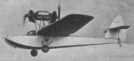
The Hinkler Ibis was a two-seat all wooden monoplane powered by two Salmson AD.9 radials mounted in an over-fuselage nacelle, one pusher, one tractor, Designed and built by H.J.Hinkler and R.H.Bound at Hamble in 1929. Construction of the wing was sub-contracted to Hendy Aircraft Ltd at Shoreham.
It was flown for the first time in May 1930 at Hamble. Registration was G-AAIS c/n 1.
It was put into store in Southampton until 1953 when it was displayed statically for a brief period until it was broken up at Lee-on-Solent in 1959.
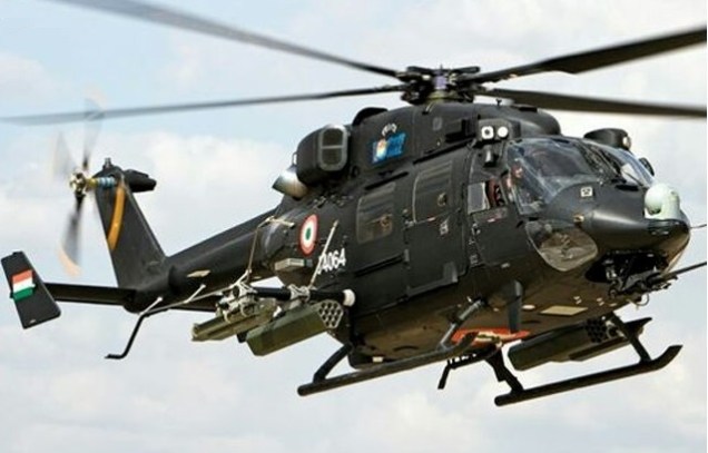
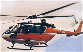
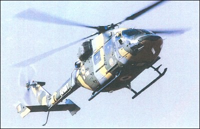
The indigenously designed and developed Advanced Light Helicopter is a twin-engine, multi-role, multi-new generation helicopter in the 5.8-tonne weight class. The multi role helicopter is powered by two Shakti Engines.
The features that are unique to LCH are sleek and narrow fuselage, tri-cycle crashworthy landing gear, crashworthy and self-sealing fuel tanks, armour protection and low visibility features which makes the helicopter lethal, agile and survivable.
Indigenously-developed weapon system integrated helicopter Rudra was to make its maiden appearance in the Republic Day parade on Rajpath on January 26 2018.
It is equipped with a 20 mm Turret Gun and 70 mm Rocket System and has a facility for air to air missile system.
The LCH is fitted with Self Protection Suite consisting of Radar/Laser Missile warning systems and Countermeasures dispensing system.
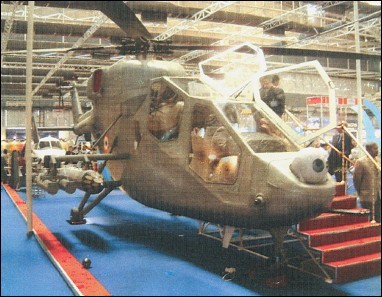
An attack helicopter derivative of Dhruv, displayed in model form at the Paris Air Show, June 2001 as LAH (light attack helicopter) proposal, but was restyled LCH, signifying light combat.
The original slimmed-down ‘gunship’ fuselage was discarded and the basic Dhruv airframc retained except for the forward fuselage modified to tandem crew seating. Officially launched on 5 February 2003, the LCH replaced the earlier LOH programme, which was met by a foreign design. The LCH was scheduled to fly in 2005, and intended to augment, and eventually replace Indian Air Force Mi-35 fleet.
The design features a four-blade hingeless main rotor with swept blade tips. Intended for anti-tank, close air support, air-to-air combat and scout roles, extensive use of composites is to reduce radar signature.
Landing gear is a non-retractable tricycle type and power is by two 895kW Turbomeca/HAL TM333-2C2 Ardiden 1H turboshafts (Indian name Shakii) with FADEC, derated to 798kW.
Systems include a four-axis autostabilisation system; anti-resonance isolation system (ARIS).
Armament is an undernose 20mm cannon and stub-wing hardpoints for ASMs, AAMs or rocket launchers.
HAL LCH Engines: two 895kW Turbomeca/HAL TM333-2C2 Ardiden 1H turboshafts Main rotor diameter: 13.20m Length overall, rotors turning: 15.86m Fuselage length: 13.94m Height to top of rotor head: 5.27m Stub-wing span: 4.43m Max. take-off weight: 5,500kg Empty weight: 3,243kg Never-exceed speed: 330km/h Max cruising speed: 280km/h Service ceiling: 6,500m Range with standard fuel: 700km
An agreement was signed with MBB (Germany) in July 1984 to support design, development and production of an Advanced Light Helicopter (ALH), design starting in November 1984. Ground test vehicle runs began in April 1991.
Five flying prototypes (two basic, one air force/army, one naval and one civil) were built. PT1 first civil prototype (Z3182) rolled out 29 June 1992; first flight 20 August and ‘official’ first flight 30 August 1992 PT2 second civil prototype (Z3183) made its first flight 18 April 1993 PT-A (army/air force prototype Z3268) on 28 May 1994 PT-N (naval prototype), with CTS 800 engines and a retractable tricycle undercarriage, flew for first time (IN901) on 23 December 1995
Total hours flown, including ‘hot-and-high’ trials in environments of 45°C and more than 6,000m, were about 1,500. Military certification of air force/army, naval and coast guard versions was completed in March 2002.
Versions:
Air force/army: Skid gear, crashworthy fuel tanks, bulletproof supply tanks, IR and flame suppression; night attack capability; roles to include attack and SAR.
Naval: Retractable tricycle gear, harpoon decklock, pressure refuelling; fairings on fuselage sides to house mainwheels, flotation gear and batteries.
Civil: Roles to include passenger and utility transport, commuter/offshore executive, rescue/emergency medical service and law enforcement. Wheel landing gear. Prototype targeted to fly in 2001, but this not achieved until 6 March 2002; DGCA certification to be followed by FAA/JAA type approval. Civil version entered production in 2003. Launch customer Azal India Helicopter (one ordered 5 February 2003, for delivery later that year).
Coast Guard: High commonality with naval version; nose-mounted surveillance radar; roof-mounted FLIR; starboard side, cabin-mounted 7.62mm machine gun; radar console and operator’s seat; liferaft, loudhailer.
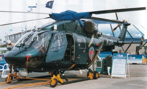
The first modern helicopter of local design and construction. Conventional layout, including high-mounted tailboom to accommodate rear-loading doors-hour-blade hingeless main rotor with advanced aerofoils and sweplback tips; Eurocopter FEL (fibre elastomer) rotor head, with blades held between pair of cruciform CFRP starplates; manual blade folding and rotor brake standard; integrated drive system transmission; four-blade bearingless crossbeam tail rotor on starboard side of fin; fixed tailplane; sweptback endplate tins offset to port; vibration damping by Lord ARIS (anti-resonance isolation system), comprising four isolator elements between main gearbox and fuselage.
Main rotor blade section DMH 4 (DMH 3 outboard); tail rotor blade section S 102C (S 102E at tip). Rotor speeds 314 rpm (main), 1,564 rpm (tail).
Flying controls are integrated dynamic management by four-axis AFCS (actuators have manual as well as AFCS input); constant-speed rpm control, assisted by collective anticipator (part of FADEC and stability augmentation system acting through ATCS).
The main and tail rotor blades and rotor hub glass fibre/carbon fibre; Kevlar nosecone, crew/passenger doors, cowling, upper rear tailboom and most of tail unit; carbon fibre lower rear tailboom and fin centre panels; Kevlar/ carbon fibre cockpit section; aluminium alloy sandwich centre cabin and remainder of tailboom.
Landing gear is non-retractable metal skid gear standard for air force/army version. Hydraulically retractable tricycle gear on naval and civil versions, with twin nosewheels and single mainwheels, latter retracting into fairings on fuselage sides which also (on naval version) house flotation gear and batteries; rearward-retracting nose unit; naval version has harpoon decklock system. Spring skid under rear of tailboom on all versions, to protect tail rotor. FPT Industries (UK) Kevlar inflatable flotation bags for prototypes, usable with both skid and wheel gear.
The first three, and fifth, prototypes each powered by two Turbomeca TM 333-2B2 or -2C turboshafts, with FADEC, rated at 740kW for T-O, 783kW maximum contingency and 666kW maximum continuous. LHTEC CTS 800-4H (998 kW) selected late 1994 and test-flown in the fourth prototype, but subsequently embargoed; all then went to TM 333-2B2 until availability of 895kW class Ardiden 1H (Shakti) in about 2006. The twin turboshafts are mounted above the cabin.
Transmission ratings (two engines) 1,280kW for 30 minutes for T-O and 1,156kW maximum continuous; OEI ratings 800kW for 30 seconds (super contingency), 700kW for 2.5 minutes. Transmission input from both engines combined through spiral bevel gears to collector gear on stub-shaft. ARIS system gives 6° of freedom damping. Power take-off from main and auxiliary gearboxes for transmission-driven accessories.
Total usable fuel, in self-sealing crashworthy underfloor tanks (three main and two supply), 1,400 litres. Pressure refuelling in naval version. Crossfeed and fuel dump systems in all military versions.
Flight crew of two, on crashworthy seats in military/naval versions. Main cabin seats 12 persons as standard, 14 in high-density configuration. EMS interior (first flown by PT2/Z3183 in January 2001) can accommodate two stretchers and four medical attendants, or four stretchers and two medical personnel. Crew door and rearward-sliding door (military) or hinged door (civil) on each side; clamshell cargo doors at rear of passenger cabin.
DC electrical power is from two independent subsystems, each with a 6kW starter/generator, with battery back-up for 15 minutes of emergency operation; AC power, also from two independent subsystems, each with a 5/10 kVA alternator. Three hydraulic systems (pressure 207 bar, maximum flow rate 25 litres/min; systems 1 and 2 for main and tail rotor flight control actuators, system 3 for landing gear, wheel brakes, decklock harpoon, rescue hoist (naval variant) and optional equipment. Oxygen system.
Avionics: Comms: V/UHF, HF/SSB and standby UHF com radio, LFF and intercom. Radar: Weather radar optional. Surveillance radar in Coast Guard version. Flight: SFIM four-axis AFCS, Doppler navigation system, TAS system, ADF, radio altimeter, heading reference standard. GPS nav system in civil version, with additional VOR/ILS, DME and marker beacon. Mission: Roof-mounted FLIR in Coast Guard version. EMS version equipped with navaids, patient monitoring, data recording systems, and datalink to transmit medical information to ground-based hospitals.
A 1,500kg capacity cargo sling can be fitted.
Armament is cabin-side pylons for two torpedoes/depth charges or four anti-ship missiles on naval variant; on army/air force variant, stub-wings which can be fitted with eight anti-tank guided missiles, four pods of 68mm or 70mm rockets or two pairs of air-to-air missiles. Army/air force variant can also be equipped with ventral 20mm gun turret or sling for carnage of land mines. Cabin-mounted 7.62mm machine gun in Coast Guard version, firing from starboard side doorway.
Naval trials by PT-N conducted in March 1998 aboard aircraft carrier INS Viraat and smaller decks of other Indian Navy vessels. May 1998 US trade embargo, imposed following India’s refusal to sign nuclear test ban treaty, blocked import of CTS 800 engines (30 ordered) and delayed planned first flight of PTC-2 civil fifth prototype (VT-XLH) with this engine until 6 March 2002. Instead, all variants were to be powered by TM 333, including retrofit of PT-N prototype; contract announced 7 February 2003 for HAL to co-develop and co-produce Turbomeca Ardiden 1H (Indian name Shakti) for future, higher-powered versions of Dhruv. Weight reduction programme initiated in mid-1998; RFPs issued later same year for cockpit display system. By the end of 1998, manufacture was well advanced of three preproduction aircraft (PPN-1, PPA-2 and PPA-3: one for each of the three armed services).
Indian government requirement for armed forces and Coast Guard, to replace Chetaks/Cheetahs; letter of intent for 300 (Army 110, Air Force 150, Navy/Coast Guard 40) followed by contract for 100 in late 1996, but allocation revised by 2001 as Army 120, Navy 120, Air Force 60 and Coast Guard seven; all to be delivered by 2015. Second production lot contains 20.
Deliveries (four each to Indian Air Force and Army, two each to Navy and Coast Guard) were due to begin in late end of 2001, to be followed by two each to Coast Guard, Navy and Air Force by the end of March 2002. Seven deliveries actually achieved by this date: Army two (IA-1101 and -1103) starting 20 March 2002, Air Force two (J-4041/4042 on 20 March), Navy two (IN-701 /702 on 28 March) and Coast Guard (CG-851 on 18 March) one. However, Army’s IA-1102 had been delivered for trials use earlier, on 4 January 2003. Eight more scheduled for delivery by 31 March 2003, of which Indian Navy received two on 24 March. Initial batch of 30 TM 333-2B2 engines ordered in mid-1999 to power first 12 (including two civil) production Dhruvs; all then intended for delivery by 2002. Further 52 engines ordered mid-2000 to power next 20; deliveries of these almost completed by February 2003; further contract at that time for over 300 more, for delivery from early 2004. Hindustan Aeronautics showed the ALH / Dhruv (Polaris) at the 2003 Paris Air Show. Unit price of basic aircraft approximately Rs250 million (US$5.1 million) (2002). Total programme costs US$170 million by 1997.
Initial Indian Army aircraft were delivered to 201 Squadron.
Development and marketing agreement between HAL and Israel Aircraft Industries announced in late 2002; involves both Dhruv and LAH derivative; IAI to concentrate on avionics and other internal systems.
ALH Engines: 2 x Turboméca TM 333 2B, 986 shp Length: 42.29 ft / 12.89 m Length rotors turning: 15.87m Fuselage length: 12.89m Height: 12.336 ft / 3.76 m Rotor diameter: 43.307 ft / 13.2 m Max take off weight: 12127.5 lbs / 5500.0 kg Weight empty: 4886.3 lbs / 2216.0 kg Max. speed: 151 kts / 280 km/h Cruising speed: 132 kts / 245 km/h Initial climb rate: 1771.65 ft/min / 9.00 m/s Service ceiling: 19685 ft / 6000 m Hovering ceiling: 3000m Maximum range: 432 nm / 800 km Range: 216 nm / 400 km Crew: 2 Payload: 14pax (max 1500kg)
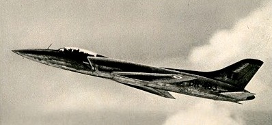
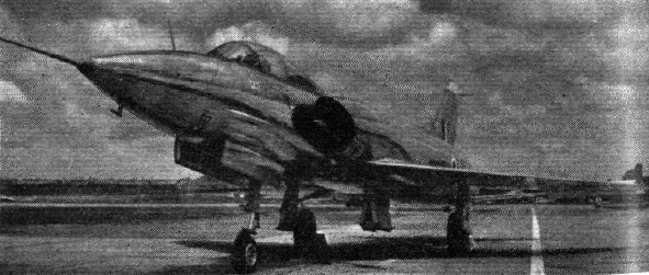
Designed by a team led by Kurt Tank, HAL produced the HF 24 Marut for the Indian Air Force as a single seat ground attack fighter with subsonic performance. Work on the project began in 1955, to meet an Indian Air Force requirement, and first flight tests of the aerodynamic envelope were made in March 1959 with a full scale wooden glider.
The prototype first flew on June 17, 1961 powered by two 4850 lb thrust Bristol Siddeley Orpheus 703 turbojets. The prototype has room for a second pilot, with dual controls, in the rear of the cockpit, but this space was to be normally occupied by armament, fuel, cameras or electronic equipment.
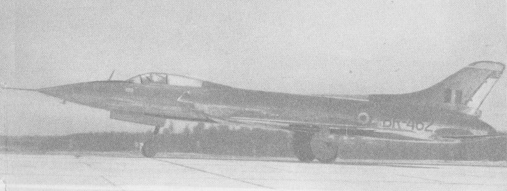
First prototype
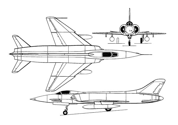
The airframe has sharply swept low wings, sweptback tail surfaces, and one-piece all-moving tailplane low-set on the fuselage. The fuselage is area-ruled and semi-circular engine intakes, with central shock body are on each side of the cockpit. The tricycle undercarriage has single wheels on each unit. The main units retract inward and nose-wheel retracts forward.
Hindustan HF-24 1st prototype
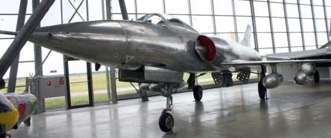
Production of 129 (plus 18 two-seat HF-24 Mk 1Ts two seat operational trainers) ended in 1977. Power for each production aircraft is provided by two 4,850 lb thrust Rolls Royce Bristol Orpheus 703 turbojet engines and armament comprises four 30 mm Aden cannon and 50 68 mm air to air rockets carried in a retractable pack in the lower fuselage. Underwing stations can carry the usual selection of bombs, rockets, napalm tanks, and drop tanks.
HF-24 Marut preserved at the Oberschleissheim museum near Munich.
Marut Mk.1 Engine: 2 x HAL/Rolls-Royce Orpheus Mk 703, 21.6kN Max take-off weight: 10908 kg / 24048 lb Empty weight: 6195 kg / 13658 lb Wingspan: 9.0 m / 29 ft 6 in Length: 15.87 m / 52 ft 1 in Height: 3.6 m / 11 ft 10 in Wing area: 28.0 sq.m / 301.39 sq ft Max speed: 1070 km/h / 665 mph Cruising speed: 486 kts / 900 km/h Ceiling: 12000 m / 39350 ft Range: 800 km / 497 miles Crew: 1 Armament: 4 x 30mm Aden cannon /120rds, 50 x 68mm missiles / 1816kg ext Hardpoints: 4
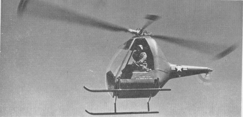
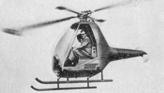
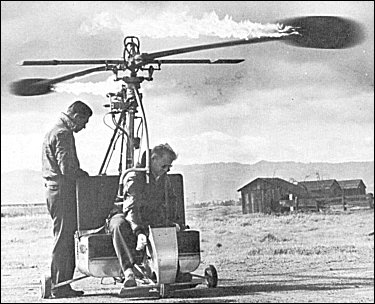
Early in 1952, Hiller approached the Navy about authorizing construction of an evaluation quantity of Hornets. The proposal was accepted because it was felt that a revised Hornet might meet a Marine Corps requirement for an ultralight flying vehicle. By summer a fixed-price contract had been negotiated for delivery of five units, three to go to the Navy as the HOE-1. Impressed by the simplicity of the original HJ-1, the Army asked to take the remaining two (serials 53-4663 and -4664) under the designation YH-32. At the end of 1954, Army officials ordered a dozen more Hornets (55-4963 through -4974), and Hiller’s own test and demonstration requirements brought the total of second-generation Hornets to twenty-five, including the three ULV gunships. The twelve aircraft were all delivered by late 1956. This evaluation quantity of HOEs and YH-32s marked the first production of tip-jet-powered helicopters in history, and the first procurement of such vehicles by U.S. military services.
Although the new military helicopter shared the name and designation of the original HJ-1 “Hornet”, it was an all-new machine with no commonality. It had lightweight skids, and it had rudder pedals controlling a single-blade tail rotor. While not needed to offset torque, the tail rotor – which furnished crisper yaw control than was provided by the earlier Hornet’s rudder – helped during autorotation and permitted rapid sideways flight as required by increasingly stringent military control requirements.
The HOE-1/H-32 was designed by both Bob Anderson and James B. Edwards, the vice president of engineering, who had come to Hiller in January 1952 from Douglas Aircraft. The HJ-1 suffered a growth in size and weight. A larger cockpit, fiberglass body and tail boom (the first structural use of fiberglass in aircraft construction), and other changes raised the empty weight from the original Hornet’s 160kg to 240kg, and the gross weight climbed to 480kg. As a result, the service ceiling fell from 3350m to 2100m. Even with 200 litres of fuel, the craft’s range shrank from 65km to 45km, its maximum powered endurance at economy cruise being roughly thirty minutes.
The joint military program by the Army and Navy had many extra-contractual changes that – including the dual certification programs – eventually consumed more than a million dollars of Hiller resources.
The first of the HOE/H-32 series flew in September 1953, with deliveries to commence the following spring. The services did not receive them until the end of 1954, because these machines had been procured on a “certification specification” basis rather than on the standard “mil. spec.” basis, and civil certification of the helicopter and its engine would take time, as both were new to the experience of the CAA. The 8RJ2B ramjet engine was a refined and uprated version of the unit Hiller had developed in 1949. Now eight inches in diameter and weighing 5.7kg, it produced the equivalent of 45hp. Manufactured by Ryan in San Diego under license from Hiller, the 8RJ2B was made out of lnconel X, a high-nickel alloy. Because Inconel X corrodes on contact with lead – then commonly found in automotive gasoline, which was a likely fuel for this engine – the engine’s interior was coated with a protective ceramic material. By August, the 8RJ2B had logged 559 hours in the air, 2104 hours on the whirlstand, and 1545 hours in free airstream static tests. Its early teething troubles had been completely solved, even the once nagging problem of flameouts. If flameouts should occur, the engine now reignited itself so quickly that the pilot never perceived the problem. Another selling point was the remarkable portability and simplicity of the 8RJ2B. An untrained person could change a Hiller Hornet’s engine in just three minutes with a screwdriver.
Ramjet testing on the ground included static duration runs, which were a sore point with residents of Belle Haven and East Palo Alto. One test in March 1953 lasted 200 hours, while another the following February ran for 150 hours. At night an inversion would often form over the entire San Francisco Bay area, causing the bam-bam-bam of the whirling ramjets to skip over much of the local area and bounce squarely into the fashionable Atherton and Menio Park neighborhoods. Residents often telephoning the plant at Palo Alto to complain. The problem was significantly reduced in the spring of 1954 by construction of a circular barrier 5.5m high and 12m in diameter, which was designed to muffle jet engine noise. During the last days of ramjet certification in 1954, several overspeed runs were conducted on the whirlstand. At peak rpm, when the tip jet was subjected to as much as 14000 Gs (boosting its “weight” to some 80300kg), supporting bolts sheared and the 8RJ2B shot away through protective walls, acoustical barriers, and property fences before coming to rest some 150m from the test site. The test stand also departed the area, flying off toward San Francisco Bay. It was later recovered from nearby mud flats. The only known structural failure of a Hiller tip-power rotor, this test far exceeded expectations and overwhelmingly satisfied the stringent certification requirements. On October 28, 1954, the CAA awarded Hiller’s 8RJ2B engine Type Certificate No. 280, officially approving it for commercial production and sale should Hiller so desire.
Parallel certification for the “Hornet” helicopter was not granted. The reason was the cold drag problem associated with autorotation, as with the earlier HJ-1. The new military Hornets descended steeply at almost 18m/s, but their massive rotors stored so much energy that landings were simple after one became accustomed to the high sink rate. Hiller test pilot and marketing executive Robert Boughton found that whereas one would begin to flare 15 to 18m above the ground in a normal helicopter, the “Hornet” demanded that one begin pulling up on the collective a full two to three hundred feet off the ground. Enough inertia was stored in the tip engines to permit the pilot to touch down, rise into the air again, and land a second time. A solution to the unacceptably high sink rate was proposed to the military during development of the H-32 and HOE. The company suggested that the flameholders in the mouths of the ramjets be modified to function like controllable shutters. During autorotation, they could simply rotate shut to close off air-flow through the engine and greatly reduce cold drag. If one engine failed, the “Hornet” could be flown some distance to a safe landing, although it could not maintain altitude. An automatic low-fuel power reduction further enhanced safety by alerting the pilot to land while sufficient fuel remained to do so under power. Still, with range so limited and the possibility of fuel starvation so great, flameholder shutters were clearly a desirable feature. The military declined because its strict acceptance standards made no provision for such devices. Without them, the Hornet’s autorotation proved unacceptable to the CAA, which otherwise found the diminutive craft satisfactory. Civil certification was accordingly denied. Failure to achieve this production license removed any possibility of Hornets reaching the private market, although it is doubtful that Hiller would have chosen to market a civil version in any event.
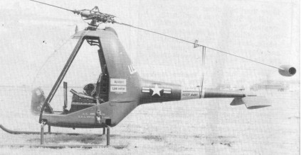
YH-32
On a warm day the Hornet could barely hover over a metre above the ground with two people and a full fuel load. The Hornet was able to run on a wide variety of fuels, but the fuel tank held only enough for 25 minutes flying or 65km range. The rotor needed to be spun to 50 rpm by a small motor before the ramjets would start. Normal operating speed was 550 rpm. Fuel pressure was then built up, fuel flow valves were opened, and the starter button was depressed to fire a spark plug in each ramjet. Ninety seconds later, the Hornet’s rotor reached 450-500 rpm and away it flew. Pilots who had the chance to try it out reported generally pleasant and forgiving characteristics.
The museum owning the only remaining flyable example of the 17 Hornets built received complaints from neighbours a mile and a half away when they last flew it.
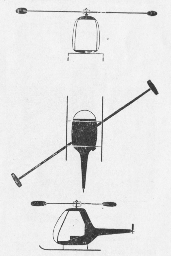
HOE-1 Engine: 2 x 8RJ2B ramjets, 17kg / 31 lb of thrust each Main rotor diameter: 7.0m / 23 ft Fuselage length: 3.45m / 12 ft. 8 in Height: 2.44m Take-off weight: 487kg Loaded weight: 1,200 lb. Empty weight: 239kg Max speed: 129km/h / 80 m.p.h Cruising speed: 111km/h Service ceiling: 3500m / 12,000 ft Range: 450km Typical range: 31 miles at 70 m.p.h. with full load. Seats: 2
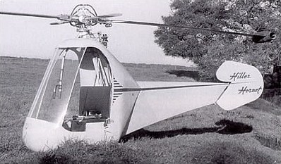
Originally intended for the civil market with a price as little as $5,000, the Hiller Hornet was a tiny helicopter powered by ramjet engines mounted on the rotor tips. Although Hiller never realized the long-held dream of flying crane production for want of government sponsorship, this program did have conspicuous successes. The comprehensive body of research it generated has paved the way for such helicopters to be built in the future, eliminating every real or imagined obstacle to their construction. This program also fostered the development of two generations of the Hiller HJ-1 Hornet. The first of these generations began with the construction of three HJ-1s in Palo Alto in 1950. Just 2.1m high, weighing 400kg fully loaded, and topped with 7m-diameter rotors, these machines were far less complex than conventional helicopters. Only their Rotormatic paddles revealed them to be Hiller machines. Frank Peterson flew the first Hiller HJ-1 “Hornet” in August day in 1950. The two-place craft was of simple construction, consisting mainly of a reinforced steel tube framework overlaid with a skin of fiberglass and plastic laminate. The Hornet was powered by two Hiller 8RJ2B ramjets, one fixed to the end of each main rotor blade, with an auxiliary one horsepower gasoline engine being used to spin the rotor blades up to the 50 rpm required prior to ignition of the ramjets. The HJ-1 “Hornet” generated substantial public interest when unveiled by Hiller in February 1951. At that time it was announced that the company might offer them for sale at less than $5,000 each. Its top speed was 130km/h, cruise was 110km/h, the service ceiling was 3350m, and the initial rate of climb was 5.6m/s. The only drawback was range, as a fully loaded HJ-1 could travel only a little under 65km. The HJ-1 was stable for a small helicopter because of its Rotormatic paddles and high-inertia rotor. The docile manners ended at autorotation. Whereas conventional helicopters autorotate at 9m/s or so, the Hiller “Hornet” plummeted at 15m/s, because the intakes of its ramjets retarded rotor windmilling. Hiller’s aeronautical engineers christened this aerodynamic braking “cold drag”. However slowly it turned during autorotation, the rotor – with the weight of ramjets at its tips – had plenty of accumulated kinetic energy left to trade for lift when the time came. One merely needed skill, nerve, and fast reflexes to know when to haul up on the collective lever. Hiller Test Pilot Bruce Jones was the first person to autorotate a tip-powered helicopter. Ground observers stood aghast as he hurtled downward in the HJ-1, came to a radical flare in the nick of time, and settled to the ground. With a mix of relief and anger, Hiller’s non-pilot contracts manager ran up to the Hornet, shouting that the craft was not insured. “Listen,” the pilot replied hotly, steadying himself on rubbery legs. “I’m lucky to be alive! The aircraft was falling at 15m/s and I was falling at 10, and I barely caught up with the controls to land the damn thing!” Jones, a veteran World War II flier and a former Bell helicopter demonstration pilot, soon became the undisputed master of Hornet autorotations. An argument arose on the Hiller flight line one summer day in 1951 over what accuracy, if any, was possible during “deadstick” landings. Jones settled the issue once and for all by autorotating from 900m to land within 15m of dead center of the Hiller apron. With no torque to counter, the “Hornet” dispensed with a tail rotor in favor of a simple airplane-style rudder canted to take advantage of rotor downwash. Pedals were likewise eliminated; side-to-side movement of the collective lever worked the rudder to provide yaw control. An overhead cyclic stick provided lateral and longitudinal control as in the early model 360. On the touchy subject of noise, Hiller publicity releases optimistically stated that “the Hornet’s sound range compares favorably with that of a conventional-powered helicopter.” The “Hornet” had just two controls (cyclic and collective-cum-rudder) and tachometer, fuel flow gauge, airspeed indicator, altimeter, and starter button on its instrument panel. The Korean War preempted plans to market the HJ-1. Viewing its rapidly expanding backlog of military helicopter orders, and an uncertain public demand for the HJ-1, Hiller Helicopters announced in September 1951 that plans for marketing a civil version of the Hornet had been indefinitely deferred.
A side-by-side two seat ultra-light helicopter with two Hiller ramjets attached to the ends of the rotor blades. No tail rotor and fixed tricycle undercarriage. One prototype was built, registered N6728C.
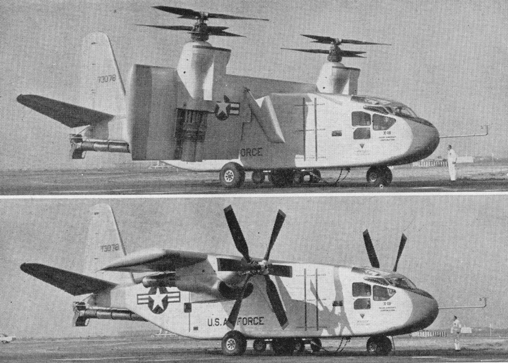
A prototype in the VTOL arena was the 33,000 lb Hiller X-18 tilt-wing convertiplane. The X-18 took to the air for the first time in November 1959, and in overall concept was configured as a transport type. Power was provided by two 5850-shp (4362-kW) Allison T40-A-14 turboshafts driving the two contra-rotating propeller/rotor units located one on each wing, and a 3400-lb (1542-kg) thrust J34 turbojet providing exhaust gases to a tail-mounted thrust diverter used for longitudinal control in vertical flight.