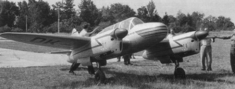
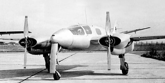
One of three new Czechoslovak prototypes unveiled at an international airshow held at Prague-Ruzyne airport on September 7, 1947, was the civil HK-101 light twin.
Engines: 2 x Walter Minor 4-III.
One of three new Czechoslovak prototypes unveiled at an international airshow held at Prague-Ruzyne airport on September 7, 1947, was the civil HK-101 light twin.
Engines: 2 x Walter Minor 4-III.
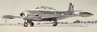
The HA-300P research glider was to provide advance information on the probable flight characteristics of the powered aircraft.
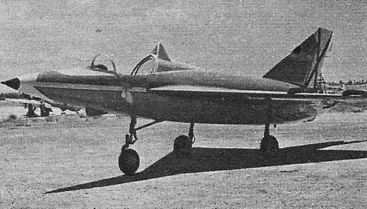
Rolled out of Military Factory No. 36 at Helouan for the first time in 1963, the Messerschmitt designed supersonic interceptor was expected to commence flight trials with an Indian test pilot. Development on the Hispano HA 300, or, XC 6, began in Spain and was subsequently shelved. The fighter is powered by two 4,850 lb.s.t. (2 200 kgp) Bristol Siddeley Orpheus 703 turbojets for initial flight trials, but the definitive version is expected to be powered by a pair of 7,000 lb.s.t. (3 175 kgp) turbojets of a type developed in Egypt by Ferdinand Brandner. Whereas the fighter is only likely to attain about Mach 1.2 with Orpheus engines, a maximum speed of the order of Mach 2.2 is anticipated with the Brandner designed engine which, if successful, may also power the Hindustan HF 24. Basically of clipped delta planform, and featuring a long, needle nose, the fighter has side by side mounted engines, a narrow track, fuselage housed undercarriage, and a Martin Baker zero altitude ejection seat.
HA-300P
Wingspan: 20 ft 2 in
Length: 33 ft 5.5 in
Wing area: 215.278 sq.ft
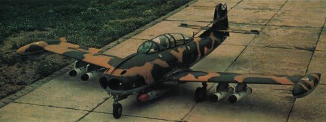
HA 200 Saeta development potential as a lightweight ground attack aircraft lead, via the two seat HA 200E Super Saeta with more powerful Marbore engines, to the purpose built, single seat HA 220 Super Saeta, with increased armour, self¬-sealing fuel tanks and an additional fuel tank in the rear cockpit, replacing the second seat. Powered by two 1,058 lb thrust Marbore VI engines, the rear cockpit is used to accommodate an additional fuel tank. Armament can comprise a variety of bombs, guns, and rockets on under-¬fuselage/wing stations.
Two Browning M 3 machine guns.
Prototype (XC.10C) flown for first time on April 25, 1970. EdeA designation C.10C, later A.10C.
Twenty five were built.
Military Users: Egypt, Spain.
HA 220 Super Saeta / C-10C
Wing span: 35 ft 10 in (10.93 m)
Maximum speed: 435 mph (700 km/h).

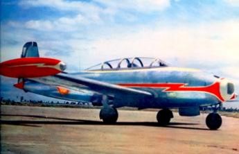
Hispano decided to build a basic jet trainer using two Marbore II engines, and designed the HA.200 Saeta (Arrow) Spain’s first jet aircraft which used many components from the HA.100 Trianaa, including the wings and rear fuselage.
Willy Messerschmitt supervised the design. The engines, mounted in the lower forward fuselage, were fed from an air intake in the nose, and exhausted from two nozzles below the trailing edge of the wing roots. The HA.200 stored its fuel in two wing and two fuselage tanks.
Two prototypes were built and first flew on 12 August 1955 with the Fernando Juan Valiente. 190 were built, both by Hispano and under a licence agreement in Egypt (as the Helwan HA 200B AI Kahira).
From the autumn of 1957 an experimental program was initiated by INTA. Ten pre-production aircraft were ordered by the Spanish Air Force, of which 5 will be transformed into HA-200 A (E14A Ejército del Aire in). The first aircraft was to fly on July 21, 1960, the rest be be delivered until 1962.
An additional series of 30 HA-200 A was built. The first of them flew October 11, 1962, the others being delivered between 1963 and 1965. In April 1965 flew the first HA-200 B (C10B in Ejército del Aire service) of which 55 were built and incorporated in the Ejército del Aire over 1965-1967.
Hispano’s Saeta fulfilled jet training, ground attack training and, in the dedicated single seat HA.220 model, limited strike roles in Spainish service. The indigenous CASA 101 Aviojet provided the replacement, deliveries commencing in 1980.
The Egyptian aircraft were supplanted by the Aero L 29 Delfin.
Variants:
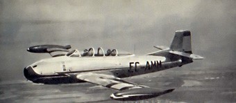
HA 200R Saeta
Prototype EC AMM first flew on August 12, 1955, followed by second prototype. Spanish Air Force (Ejercito del Aire EdeA) designation XE.14 for the prototypes and E.14 for 10 pre-production examples, five of which were brought up to HA 200A status.
HA 200A Saeta
First production batch (of 25), powered by Turbomeca Mabore lls, first example flown on October 11, 1962. Much refined over earlier HA.200s. EdeA designation E.14A. Attack version (two hard points) C.10A, later A.10A.
HA 200B AI Kahira
Version for Egyptian Air Force. 20mm Hispano cannon in the nose, replacing 7.7min Breda Safat machine guns of the HA.200A. First of five Spanish built examples flown on July 21, 1960. 63 HA¬200Bs built under licence in Egypt as the AI Kahira (Cairo) at Factory 36, Helwan, Cairo.
HA 200D Saeta
Further refined production batch, EdeA designation E.14B. 55 built.
HA 200E Saeta
Dedicated ground attack/counter insurgency aircraft, with four wing hardpoints and Mabore VIs. Conversions (about 40) undertaken from HA 200Ds, designated C.10Bs then A.10Bs.
Wing span: 36.17 ft (10.42 m)
Overall length: 29.29 ft (8.9 m)
Height: 9.33 ft (2.8 m)
Wing area: 187.2 sq.ft (17.4 sq.m).
Wing aspect ratio: 6.22.
Empty wt: 4233 lb (1921 kg).
Normal T/O wt: 5842 lb (2652 kg).
MTOW: 7617 lb (3458 kg).
Internal fuel cap: 164 Imp.Gal. (745 lt).
External fuel cap: 106 Imp.Gal. (481 lt).
Wing loading: 31.2 lb/sq.ft (152 kg/sq.m).
Max speed: 435 mph (699 kph)
Initial ROC: 2755 fpm (14 m/sec)
TO dist 50 ft: 1740 ft (530 m)
Range: 930 sm (1496 km).
Hispano Aviation HA 200 D Saeta
Engine: 2 x Turboméca Marboré II A, 3924 N
Length: 29.429 ft / 8.97 m
Height: 10.696 ft / 3.26 m
Wingspan: 35.860 ft / 10.930 m
Max take off weight: 8048.3 lb / 3650.0 kg
Max. speed: 352 kt / 652 km/h
Service ceiling: 39370 ft / 12000 m
Range: 810 nm / 1500 km
Crew: 2
HA 200 R1
Engines: 2 x 880 lbs.t. (400 kgp) Turborneca Mabore IIA turbojets
Max speed, 435 mph (700 kph) at 22,966ft (7 000 m)
Cruise, 298 mph (480 kph)
Initial climb, 3,345 fpm. (17 m/sec)
Service ceiling, 41,000 ft (12 500 m)
Range, 1,056 mls (1 700 km)
Empty weight, 3,697 lb. (1677 kg)
Loaded weight, 6,305 lb (2 860 kg)
Span, 34ft 2.25 in (10.42 m)
Length, 29ft 1.5 in (8.88 m)
Wing area, 187.2 sq.ft (17,4 sq.m)

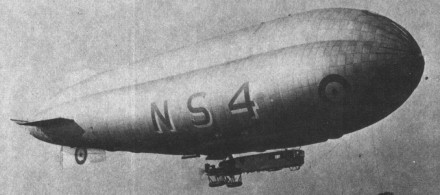
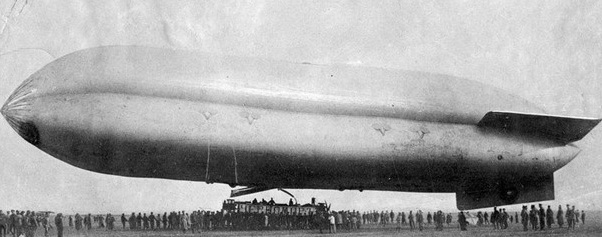
Another trefoil-section vessel, the ‘North Sea or ‘NS’ class was the last non-rigid airship type to be built for the Royal Navy, the first being ordered in January 1916 and delivered to the naval air station at Pulham in February 1917. The original idea had been for an airship which could carry out convoy duties and also co-operate with naval surface vessels, a concept that was never put into practice, the whole ‘NS’ fleet being used for patrol duties. One reason for this decision was the trouble that was experienced with the Rolls-Royce engines first fitted, the problem lying with the over-long shafting, about 3.05 m (10 ft) in length. It was only when this complicated transmission and the engines had been exchanged for direct-drive Fiats, that the type was able to prove its usefulness; previously only 18 were delivered, a mere 12 being with operational units.
Although a variety of car configurations was encountered, all of them were of similar lines, with the power-plant mounted in a separate nacelle joined to the crew quarters by a wooden catwalk. This forward part of the car had been designed with some consideration to the comfort of its occupants. Such additions as a chart table and bunks were now essential, since the 10 men aboard were expected to operate as two watches, five being on duty while the remainder rested.
From July 1917 the small number of North Sea airships then in use were all based on the Firth of Forth at East For¬tune, but by the end of the war over 100 had seen service. An early example (NS14) had gone to the United States and become A5580, while NS6 became a familiar sight to Londoners as a result of its frequent appearances over the capital; and in 1919 NS11 established an endurance record for a non¬stop cruise of 6437 km (4,000 miles) in 101 hours.
Although its primary duty was to attack U-boats with its cargo of bombs, an historic use for NS7 and NS8 was to make up the aerial force with the British fleet sent to accept the surrender of the German naval forces on 21 November 1918. All convoy protection and coastal patrol airships carried about 181 kg (400 lb) of bombs with which to attack U-boats, but the useful load varied with the water ballast carried. Earlier models of the ‘NS’ class were powered by a pair of 186.4-kW (250-hp) Rolls-Royce engines, while latterly NS12 to NS18 received 223.7-kW (300-hp) Fiats.
Type: convoy escort airship.
Powerplant: two 186.4-kW (250-hp) Rolls-Royce Eagle III V-12 or 193.9-kW (260-hp) Fiat A.12 six-cylinder water-cooled piston engines
Maximum speed 93 kph (55 mph)
Service ceiling about 7010 m (23,000 ft)
Range 4828 km (3,000 miles)
Useful lift 3810 kg (8,400 lb)
Width 17.30 m(56 ft 9 in)
Length 79.86 m (262 ft 0 in)
Volume 10194 cu.m (360,000 cu ft)
Armament: four or five 7.7-mm (0.303-in) Lewis machine-guns on free mountings, plus bombs
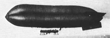
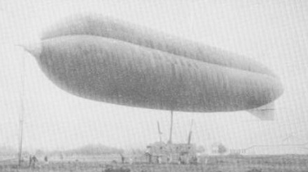
Designated the ‘C’ class from its anticipated use as a coastal type (‘Coastal’ class was an alternative name), this non-rigid type was of medium size and constructed with a trefoil envelope section, frequently known as the Astra Torrès type. The first of the pattern was ordered in June 1915 from Kingsnorth where it was assembled in the following September. The choice of envelope construction posed problems that were overcome in an interesting manner. Among these was the method of car suspension: the cables for this purpose were attached along the intersection line of the lobes and from here ran through the bottom of the covering to the car. And it is noteworthy that though the gas cells were contained in a non-rigid structure, it was possible to site one of two defensive gun positions on top.
Pembroke was the first naval air station to have the type, and the first flights took place from here in June 1916, other bases being Pulham, Howden. Mullion, East Fortune and Longside. The seas that came under the care of the ‘Coastal’ class airship patrols were those off the Norfolk coast, Lands End, the mouth of the Humber, the Firth of Forth and Aberdeen. Although the work of these vessels was largely unspectacular, one was the subject of an interesting set of experiments which were carried out on 6 September 1916. These were made with the first of the type, C1, in conjunction with the light cruiser HMS Canterbury, and were conducted offshore to look into the question of future developments, whereby an airship might be refuelled from a surface vessel.
A total of only 26 airships of this class were delivered, although these remained in service for lengthy periods. Thus they enjoyed a reputation for longevity as well as for extended flight times, the endurance of the design being as much as 12 hours. The crew of these airships consisted of five men, four of them in the car which also contained the two engines, fore and aft, driving tractor and pusher propellers respectively. The men’s accommodation was very considerably more comfortable than that of the fifth man, the upper gunner who had a special climbing tube through the envelope to reach his lofty position. ‘C’ class airships gave good and reliable service once the problems of cooling for the rear engine and blowing in of the nose cone had been solved.
When engines of differing powers were fitted in any one ship, the more powerful was normally that at the rear, while it is interesting to note that the cars were constructed from a pair of Avro 510 fuselages. Cl alone differed from the others in having a 57.9-in (190-ft) envelope with a 3964.4-cu.m (140,000-cu ft) capacity. The type had small variations of airscoop position and car details.
Four 1916-built Coastal airships were purchased by Russia in 1916, named Chernomor-1, 2, 3 (Name of the character of Russian fairy tale). The envelope volume was 4500 cu.m and the highest speed 80 km / h with two 173 h.p. engines.
In 1916, Chernomor-1 was at the very beginning of the next flight over the Black Sea, when engine failed. When returning to the base, the second engine failed. The situation was complicated by a decrease in the temperature of hydrogen in the envelope, which occurred as a result of the dense cloud covering the sun. The airship began to descend rapidly. The discharge of ballast and heavy equipment did not correct the situation. The gondola collided with water 10 km from the shore near the Kherson lighthouse, a boat coming to the rescue, and towed the airship to the Round Cove. When transporting the airship to the boathouse a strong wind rose, and in order to avoid the danger of damage, Chernomor-1 was dismantled. After that, it was never reassembled.
In one of the Chernomor-2 test flights, one engine failed. It was decided to land at the airfield Kachinskaya Aviation School. When landing, the second engine also failed. Despite this, the landing was done. Due to the increased wind and lack of space for safe parking, the airship “Chernomor-2” was dismantled. After that, it was never reassembled.
In the end, “Black Sea-3” was burned at the boathouse, and the “Black Sea-4” was not completed.
The C-Star class (sometimes written as C* class) of non-rigid airships or “blimps” were used by Britain’s Royal Naval Air Service for convoy escort duties during World War I. Developed from the Coastal class (often referred to as the “C class”), the Star in their designation indicated a modification of the original class which they slowly replaced in service.
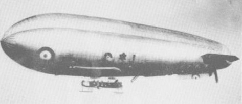
The C-Star class were slightly larger than their predecessors. With an endurance of up to 30 hours, and more powerful (and reliable) Renault engines, the C*s had the same basic layout as the Coastal Class, with the same trilobe envelope. However, the envelope tapered towards the rear, as on the SSZ class, which greatly improved stability, as did the larger control surfaces.
‘C’ class
Type: sea patrol airship
Powerplant: two 111.9-kW (150-hp) Sunbeam six-cylinder water-cooled piston engines, or one 179-kW (240-hp) Fiat and one 82.0-kW (110-hp) Berliet water-cooled piston engines
Maximum speed 80 kph (50 mph)
Service ceiling 2134 m (7,000 ft)
Useful lift 1608 kg (3,545 lb).
Width 12.04 m (39 ft 6 in).
Length 59.66 m (195 ft 9 in)
Volume 4813.9 cu.m (170,000 cu ft).
Armament: two 7.7-mm (0.303-in) Lewis machine-guns, plus bombs.
Chernomor
Volume: 4,500 cu.m
Max.speed: 80 km/h
C-Star
Powerplant: 1 × tractor-mounted Berliet, 110 hp (82 kW) & 1 × pusher-mounted Fiat, 260 hp (193 kW)
Volume: 210,000 cu ft (6,000 cu.m)
Length: 218 ft 0 in (66.46 m)
Width: 49 ft 3 in (15.01 m)
Height: 57 ft 3 in (17.53 m)
Useful lift: 4,030 lb (1,830 kg)
Maximum speed: 58 mph (93 km/h, 50 kn)
Endurance: at half speed 20 hours; at full speed 10 hours
Service ceiling: 9,500 ft (2,900 m)
Crew: Five
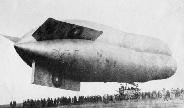
The UK’s first rigid airship was proposed in 1908 as a means of evaluating the naval airship as a weapon of war along German lines, and an order was placed with Vickers. The work was to be undertaken by a joint civilian/naval team, few of whose members had much experience in the type of work involved. Since the vessel was to be flown from water her gondolas were given planing bottoms, although alternative mooring to a mast anticipated German ideas. Construction was to be of the new alloy duralumin as a compromise between those factions who wanted wood or steel. Engine tests were begun in mid-February 1911, and it was hoped that the maiden flight might coincide with the Coronation Review of the fleet by King George V.
The extraction of HMA No. 1 (RI) from its floating shed called on the resources of a number of tugs and a hauling party of 300 sailors on the ropes, a difficult task since the airship, now nicknamed Mayfly (its official designation was ‘HMA Hermione’), proved much heavier than expected. This combined with misdirection of the handling party or (according to some reports) a sudden cross-wind, caused the airship to strike one of the uprights of the shed entrance, some damage resulting. This was unfortunate, since an earlier sojourn in the open had seen the airship successfully moored to the short mast provided as the superstructure of a naval vessel (the first use of such equipment in history) and reports speak of the RI thus riding out a storm with winds rising to as high as 72 km/h (45 mph).
The damage now sustained had to be repaired, and the airship’s return to its shed also provided an opportunity to lighten the structure. It was not until 24 September 1911 that the RI next appeared, fully loaded with hydrogen after a 10-hour inflation of the gas cells and ready for flight. The method of handling was as before, and it was necessary for the airship’s nose to be turned. Hardly had the strain been taken on the ropes than a loud crashing was heard from within the centre of the vessel as its back broke. Understandably the crew began to leap overboard as ordered, and with the weight relieved from the rear gondola the stern rose up to complete the destruction.
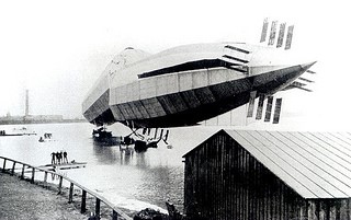
The Mayfly never flew and was later scrapped.
HMA No. 1
Engines: two 1 19,3-kW (160-hp) Wolseley eight-cylinder water-cooled piston
Estimated maximum speed 64 km/h (40 mph)
Estimated useful lift 20321 kg (44.800 lb)
Diameter 14.63 m (48 ft 0 in)
Length 156.06 m (512 ft 0 in)
Volume 18774 cu.m (663,000 cu ft)
An Advisory Committee for Aeronautics was formed in 1909, and a small dirigible, the Baby, was completed and flown. At the end of the year the Balloon School was made a separate establishment with Capper at its head, and the Factory became a civilian unit, although still under War Office direction.
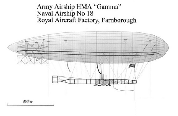
The airship Baby had been rebuilt and improved into the larger Beta, and followed by the progressively larger Gamma of 1910 and Delta. The airship was a considerable advance on Beta both in size and lift capacity, being 152 feet in length and 30 feet in diameter with an initial capacity of 75,000 cu.ft giving a gross lift of 2.1 tons.
The airship Gamma, which had been designed by Colonel Capper, successfully made its maiden flight in February 1910 at Farnborough.
During the army manoeuvres of 1910 HMA Beta and recently completed Gamma were employed in evaluating their potential use to the army in warfare: in extended flights over Somerset, Dorset, Hampshire ad Wiltshire flying reconnaissance sorties; scouting for attacking and defending forces for a period of two months; covering, in the case of Beta, in excess of 1000 miles; spending most nights moored out in the open, using the cover afforded by a screen of trees; being maintained and serviced under these basic conditions, and on one occasion having a broken crankshaft replaced within the protection of a quarry.
During 1911 wireless experiments were carried out with Gamma, where messages were received at ranges of up to 30 miles distant.
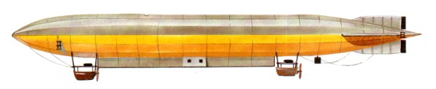
Later in 1912 Gamma was reconstructed by lengthening the envelope, increasing the capacity to 101,000 cu.ft and lift to 2.9 tons. In her final form a long, metal-framed car was suspended below a bright yellow rubberised cotton fabric envelope made by the Astra-Torres company in Paris, earning her the nickname the Yellow Peril. Power was supplied by a 35 hp four cylinder, water cooled Green engine driving swivelling propellers mounted on out-riggers from the car, giving her a still air speed of 35 mph.
The swivelling propellers were capable of moving through 240 degrees about her longitudinal axis and were most effective in controlling the ship during climbing and landing. They represented a great technical achievement for the small balloon factory staff at the time.
The envelope was sub-divided by internal tranverse partitions to prevent surging of gas, and had multiple ballonets to preserve envelope pressure.
Capacity: 101,000 cu.ft
Length: 152 ft
Width: 30 ft
Height: 52 ft
Gross lift: 2.9 ton
Disposable lift: 0.5 ton
Engines: 2 x Green 80 hp
Speed: 32 mph
Crew: 5
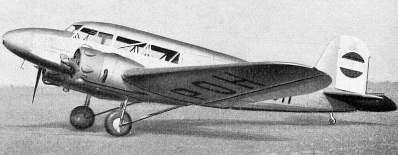
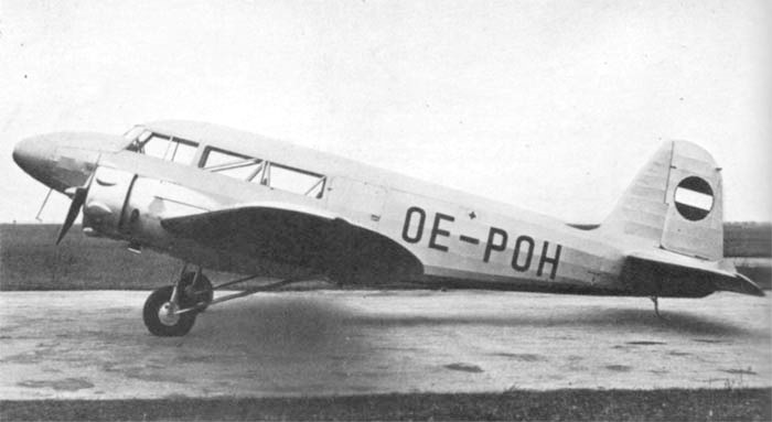
In 1935, the management of the Austrian company Hirtenberger Patronen, Zundhutchen und Metallwarenfabrik AG decided to expand the production of aircraft of its own design and bought the aircraft company Flugzeugbau Hopfner GmbH. The first aircraft, accepted for serial production, was a small twin-engine monoplane, designed for the carriage of passengers or the transport of small loads. The design of the new Hopfner / Hirtenberg HV.15 machine was based on the elements of the previous Hopfner HR.14 / 34 aircraft, developed by the engineer Lumpich in 1934 at Flugzeugbau Hopfner GmbH.
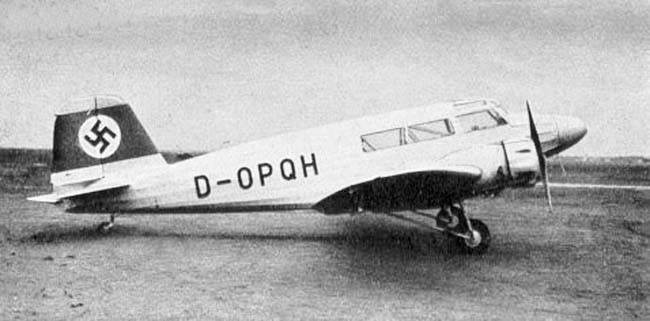
It was a low-wing with a glazed, six-seat, cabin and retractable landing gear. The wing had a wooden structure, and the fuselage was steel tube, fabric covered.
The prototype HV-15 (OE-POH) made its first flight on March 8, 1936. The aircraft was equipped with Austrian-produced Siemens Sh-14a motors (160 hp / 119 kW). Serial production were supposed to get English de Havilland “Gipsy Six” II (204 hp).
Austrian designers planned the release of the military version of NM.15, equipped with French engines of Renault “Bengali Six”, radio navigation equipment and defensive weapons, consisting of 2-3 moving machine guns placed in the fuselage. Suspension of small bombs with a total mass of up to 300 kg was envisaged. The main purpose of NM.15 was the training of pilots and navigators (including for night flights), and also considered the option of using it as a light bomber.
Serial production of HV.15 and NM.15 aircraft did not take place. After the annexation of Austria, its aviation industry underwent a reorganization, and the merger of Hirtenberg became part of the new Wiener-Neustadter Flugzeugwerke GmbH (abbreviated to WNF).
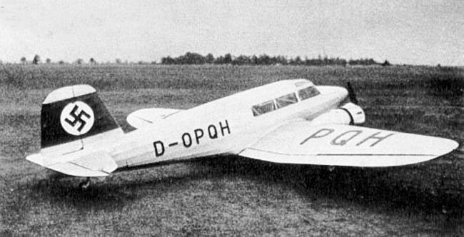
According to the new notation system, HV.15 was renamed to WN-15 (sometimes called WNF 15) and assigned the German registration D-OPQH. The prototype was then transferred to the use of the Austrian police. After flying about three years in Austria, the Wn.15 aircraft was given in 1942/1943 to the German administration of the Croatian Air Force and used some time for transport purposes, bearing a new tactical number 2101. Nothing is known about the future fate of Wn.15.
Engines: 2 × Siemens-Halske Sh 14A, 120 kW (160 hp) each
Wingspan: 15 m (49 ft 3 in)
Wing area: 33 m2 (360 sq ft)
Length: 10.65 m (34 ft 11 in)
Height: 2.9 m (9 ft 6 in)
Empty weight: 1,550 kg (3,417 lb)
Gross weight: 2,200 kg (4,850 lb)
Maximum speed: 235 km/h (146 mph; 127 kn)
Cruise speed: 198 km/h (123 mph; 107 kn)
Range: 900 km (559 mi; 486 nmi)
Service ceiling: 5,200 m (17,100 ft)
Crew: 2
Capacity: 4 passengers
The Hirsch–MAéRC H-100 was a one-off research aircraft designed by Frenchman René Hirsch to test his system to deal with gusts that make for bumpy and uncomfortable flying.
It incorporated a system in which the halves of the horizontal tail moved on chordwise hinges to operate flaps on the wings. The conventional elevators provided not only pitching moments, but moved the tail halves about their chordwise hinges to cause the flaps to move in the direction to provide direct lift control. In this way, the loss of longitudinal control due to the gust-alleviation system was overcome. Of wooden construction, the H-100 incorporated many other ingenious features, including swivelling wingtips for reducing rolling moments due to rolling gusts and lift due to horizontal gusts. The design also incorporated large pneumatic servos operated by dynamic pressure to restore damping in roll and to stabilize the rate of climb or descent.
The single aircraft built was retired after 130 test flying hours and was then donated to the Musée de l’Air et de l’Espace, at Le Bourget, Paris, where it remains on display.
