The Hughes XV-9 (company designation Hughes Model 385) was a 1960s American high-speed research helicopter built by Hughes Helicopters.
Convinced that the use of gas pressure to drive rotors, as used in the XH-17 and proposed for the XH-28, was superior to conventional methods as the elimination of the transmission drive system resulted in a lighter, less complex, and more easily maintained system, Hughes engineers sought ways to improve the propulsive efficiency of pressure-jet rotors. Eventually concluding that much improvement would result from ducting the hot efflux of gas generators directly to cascade vanes at each blade-tip instead of piping cold air to tip-burning nozzles, they succeeded in attracting the interest of the US Army.
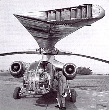
Funded by the Army beginning in 1962, the multi-phase development programme for the Model 385 began with 60 hours of test running of a prototype hot-cycle rotor mounted on a ground rig. As results were encouraging, Hughes proceeded to the next phase, 15 hours of bench testing of the Model 385 propulsion module consisting of two General Electric YT64-GE-6 gas generators mounted at the tips of stub wings and driving a three-bladed rotor. Each blade was of two-spar construction with the hot efflux of the gas generators being taken to vanes at their tips by means of a Rene 41 high-temperature steel duct passing between the spars. Cooling air was forced through the leading and trailing edges of the constant-chord blades and was exhausted at the tip, fore and aft of the hot efflux. Results remaining promising, Hughes was authorized to proceed with the manufacture and testing of a research vehicle, the XV-9A (serial 64-15107), which was given a VTOL mission designator instead of the more traditional H helicopter designator.
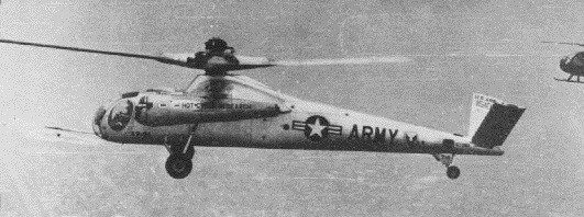
As the XV-9A was only intended as a demonstrator for the hot-cycle system, the Army requested that manufacturing costs be kept to a minimum by using components from other aircraft. Thus, the cockpit of a Hughes OH-6A (with side-by-side accommodation for a pilot and a co-pilot/flight test engineer) and the undercarriage of a Sikorsky H-34 were mated to a specially-built fuselage and V-tail. The hot efflux from two General Electric YT64-GE-6 gas generators, which were loaned by the Navy and mounted at the tips of a stub wing, drove the three-bladed rotor. Bleed air from these generators was ducted to a yaw control system at the tail.
The system was built around two pod-mounted General Electric YT64-GE-6 engines fitted to the ends of two high-set stub wings, one on either side of the fuselage directly below the main rotor hub. Each engine’s turbine section had been removed, and hot exhaust gases were ducted directly through the rotor hub to be expelled at near-sonic speeds through vaned cascades in each of the three blade tips. Smaller exhaust ports on either side of the tail boom just forward of the rudders provided some additional directional stability.
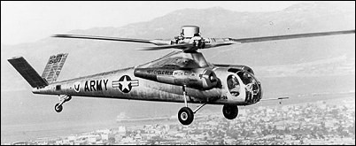
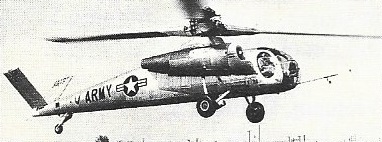
The version for the US Army was designated XV-9A and had a three-blade constant chord metal rotor. There was room for two pilots seated side by side in the cockpit.
First flown by Robert G. Ferry at Culver City on 5 November, 1964, the XV-9A remained at the manufacturer’s facility until it had completed an initial 15-hour flight test programme. It was then transferred to Edwards AFB, where an additional 23 hours were flown.
The tests were satisfactory and the company was confident that the hot-cycle system would be widely used, although the XV-9A was noisy and had a high fuel consumption. The company was unable to mitigate the problems and the development by Hughes of pressure-jet systems did not proceed. The Army tests were completed in August 1965, with a total of 19.1 hours having been flown, and the helicopter was returned to Hughes.
From an engineering point of view, tests proved highly satisfactory and in 1965 Hughes confidently predicted that the hot-cycle system would be used for heavy-lift military helicopters and for compound civil helicopters.
From the environmental and economic points of view, however, the XV-9A was less successful as the exhaust of hot efflux through cascade vanes at the tips of the rotor was noisy and unacceptable in urban areas and as fuel consumption rate was high. To mitigate these deficiencies, Hughes proposed a refinement of the pressure-jet concept based on the use of turbofans in lieu of gas generators. This warm-cycle system was tested in a wind tunnel and on a whirling stand but improvements were insufficient to warrant the manufacture and testing of a flying prototype, thus bringing to an end the development by Hughes of pressure-jet systems successively based on the cold-cycle principle, as used for the XH-17 and XH-28, the hot-cycle principle, as featured by the XV-9A, and the warm-cycle principle, as evaluated during whirling stand tests.
The aircraft was scheduled for delivery to the Smithsonian collection in May 1967 but actually arrived in August. It was shipped via railcar from Ft. Eustis and arrived as a wreck, which was not the Smithsonian’s understanding of the aircraft’s condition. The cockpit had been picked clean and there were multiple holes in the fuselage. Smithsonian correspondence does not make clear how much of this was due to improper handling and security by the railroad and how much was due to inadequate storage by the Army.
At some point in the early seventies, the aircraft was deemed beyond reasonable restoration and scrapped. The Smithsonian did retain most of one of the hot cycle blades and it is still in storage.
XV-9A Powerplant: 2 × General Electric YT64-GE-6, 2,850 hp (2,126 kW) each Main rotor diameter: 55 ft 0 in (16.76 m) Main rotor area: 2,376 sq ft (220.6 m2) Length: 45 ft 0 in (13.72 m) Height: 12 ft 0 in (3.66 m) Empty weight: 8,500 lb (3,864 kg) Gross weight: 15,300 lb (6,955 kg) Maximum speed: 173 mph (279 km/h, 150 kn) Cruise speed: 150 mph (242 km/h, 130 kn) Range: 165 mi (266 km, 143 nmi) Service ceiling: 11,500 ft (3,505 m) Crew: Two
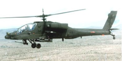
Originally a Hughes-based design, the YAH-64 faced off against a Bell YAH-63 system in the United States Army’s search for an advanced attack helicopter. The system was to field the latest in technology, maneuverability and battlefield survivability that was consistent with low-level, low-speed warfare. The end result saw the YAH-64 coming out ahead, and plans were underway to further develop the system as the principle attack helicopter of the US Army. Initial units of the now-designated AH-64A “Apache” became operational as frontline systems in 1986.
The base AH-64 was designed with crew survivability in mind featuring anti-missile systems, specialized cockpit crew protection in the form of Kevlar armor and bulletproof glass and a specially designed superstructure. The short wingtip mounts offered up four original hardpoints to which the Apache system could field the powerful and accurate Hughes AGM-114 anti-tank missile. A total of sixteen of these could be carried on the underwing hardpoints. To take on softer targets, the conventional Hydra 70 general purpose rocket pod in various munition amounts and warhead types could be fielded alongside the Hellfire. The later addition of wingtip mounts allowed the system to field AIM-9 Sidewinder or AIM-92 Stinger air-to-air missiles. The system could also support the Sidearm anti-radiation anti-radar missile air-to-surface missile. The primary standard armament of the Apache consisted of the advanced chin-mounted Hughes M230 30mm chain gun with 1,200 rounds of ammunition setup that responded to the movements of the gunners head-mounted helmet system through the IHADSS helmet sight system. Traversing is limited to 11 degrees up, 60 degrees down and 100 degrees to either side. The Apache is crewed by two personnel seated in tandem with the gunner in front and the pilot seated in back.
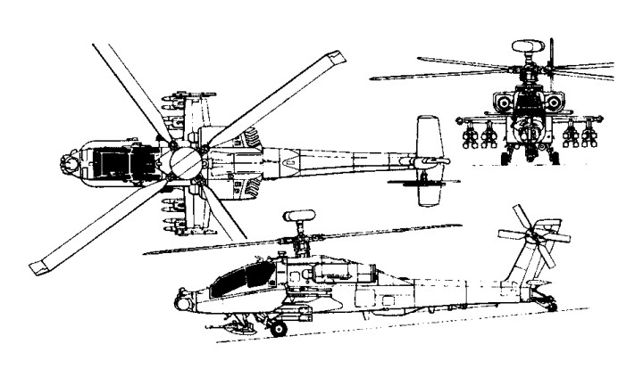
Design of the Apache was conventional with the cockpit in a stepped arrangement forward, the engines mounted high and to either side of the center of the fuselage and wing stubs just underneath the powerplants. The cockpit is designed flat glazed windows, crash supportive armored seating and reinforced landing gear struts. Engines (AH-64D) were by General Electric and featured the T700-GE-701C series turboshafts developing 1,890 shaft horsepower while driving a four blade main rotor and a four blade tail rotor. The tail rotor in and “x” type arrangement sat on the port side of the vertical tail fin. Landing gear were static with two main systems and a tail wheel. Wire cutters to improve survivability at low level were added to the top rear of the canopy, to each landing gear strut and one just forward of the chin turret base underfuselage. A chaff/flare dispenser kit was added to the aft portside of the tail assembly.
Hughes Helicopters flew the pro¬totype YAH 64 (73 22248) anti tank helicopter on 30 September 1975. The first of two for evalua¬tion against the Bell YAH 63 (the first, 73 22246, was flown on the fol¬lowing day); these were selected as finalists from design submissions for the US Army’s AAH (advanced attack helicopter) requirement. Hughes Helicopters No 5 prototype of the AH¬64 was fitted with 1,693 shp T700 GF-701 engines, in place of the 1,560 shp T700 GE 700s fitted previously in the prototypes. Hughes is proposing use of the 701 engine for pro¬duction AH 64s to improve performance in high temperatures and give better recovery in In December 1976 Hughes won a US Army competition for an Advanced Attack Helicopter. The AH 64, as it is designated, under development with Army testing was powered by two 1,536 shp General Electric T700 GE 700 turboshaft engines.
The two cockpits were separated by a two inch thick glass blast fragmentation shield and had their own air-conditioning system.
The Hughes Model 77, allocated the Army designation YAH 64A, was to prove the winner of the competition when flown and evaluated against the YAH 63 submission from Bell Helicopters. This two-seat attack helicopter is powered by 1,696 shp (1 265 kW) T700GE-701 turboshafts. Armament includes a 30-mm Chain Gun and up to 16 Hellfire ASMs. Stinger AAMs will give it an air-to-air capability. More than 550 McDonnell Douglas (originally Hughes) AH-64A Apaches had been delivered to the US Army by 1990.
After spending some time deployed at home, the AH-64A set off for West Germany in the first overseas deployment of the type. First combat deployment was a short time later in 1989’s Operation Just Cause concerning Panama and was made by the 82nd Airborne. 1991 saw the AH-64A model series deliver the opening salvos of action in Operation Desert Storm and later taking part in the much publicized “100-hour” ground war following in which some 500 enemy tanks were reportedly destroyed. Soon to follow were limited deployments in the Bosnia / Kosovo affair and finally in Operation Iraqi Freedom.
Based on lessons learned in the Gulf War of 1991, the AH-64A model was followed by the proposed upgraded AH-64B series. This model sported a Global Positioning System (GPS), improved communications and navigation and an all new main rotor blade. Most of the A models were upgraded to this standard despite funding being lost on the proposal in 1992. The AH-64C appeared (sometimes referred to as AH-64B+) and featured much of the upgrades in common with the succeeding “Longbow” version to follow, sans the mast-mounted radar system and more powerful engines. An AH-64D model also appeared but was very similar to the AH-64C series with the exception of having a removable radar.
AH-64D LongBow
The definitive Apache became the AH-64D “Apache Longbow” model. This model was distinguished by the noticeable mast-mounted AN/APG-78 Longbow radome system above the main rotor. The Longbow radar is a millimeter wave radar produced by Northrop Grumman and can guide the potent Hellfires through radar seeking frequencies for an even more improved kill ratio. Of the initial 800 or so AH-64A’s produced for the US Army, no fewer than 500 were updated to the Longbow standard. As it is mounted high on the design, the Apache Longbow need only “peer” above the treeline to ascertain enemy positions and potential targets. Target sharing was also a part of the models new suite and allowed for multiple Apaches to “talk” to one another despite one of the other not having a target locked on in its tracking system.
The Apache Longbow featured an uprated General Electric powerplant in the form of the T700-GE-701C series. Most all vital components were also updated to increase the potency of the machine while at the same time improve the crews survivability in the event of being fired upon, taking a direct hit or having to make a crash landing. The Apache Longbow remains in frontline active service and is seeing further enhancements and improvements made through additional Block updates which include new rotors, more digital automation integration with UAV battlefield elements.
The improvement programme of the AH-64 “Apache” based on Westinghouse mast-mounted Longbow millimetre-wave radar and Lockheed Martin Hellfire with RF seeker, included more powerful GE T700-GE-701C engines, larger generators for 70 kVA peak loads, Plessey AN/ASN-157 Doppler navigation, MIL-STD-1553B databus allied to dual 1750A processors, and a vapour cycle cooling system for avionics. Early user tests were completed in April 1990.
The full-scale development programme, lasting 4 years 3 months, wasauthorised by Defense Acquisition Board August 1990, but airframe work extended in December 1990 to 5 years 10 months to coincide with missile development, supporting modifications being incorporated progressively. The first flight of the AH-64A (82-23356) with dummy Longbow radome was on 11 March 1991. The first (89-0192) of six AH-64D prototypes was flown on 15 April 1992, the second (89-0228) flew on 13 November 1992, fitted with radar in mid-1993 and flown 20 August 1993. No 3 (85-25410) flown 30 June 1993; No 4 (90-0423) on 4 October 1993; No 5 (formerly AH-64C No 1) 19 January 1994 (first Apache with new Hamilton Standard lightweight flight management computer); No 6 flown 4 March 1994; last two mentioned converted from 85-25408 and 85-25477 and lack radar. First preproduction AH-64D flown 29 September 1995. Six AH-64Ds to fly 3,300 hour test programme; first remanufactured production aircraft flown 17 March 1997 and delivered to US Army 31 March 1997. IOC scheduled for June 1998. Initial AH-64D battalion (1-227 AvRgt) to be based at Fort Hood, Texas; second (3-101 AvRgt) at Fort Campbell, Kentucky.
A five year US$1.9 billion agreement for remanufacture was signed 16 August 1996. The contract covers 232 AH-64Ds over a five year period, with the entire US Army fleet of 758 AH-64As to be upgraded in remanufacture programme lasting 10 years, although only the initial 232 to carry Longbow radar. Production rate to rise from one per month in 1997 to five per month in 1999. Contract also included 227 Longbow radars (since increased to 500), 13,311 Hellfire missiles and 3,296 launchers.
Agreement reached with US Army for a US$2.3 billion contract to remanufacture a further 269 AH-64As to the AH-64D Apache Longbow configuration from FY2001, to bring total to 501 and programme to 2006. First flight of Apache with initial enhancements incorporating COTS technologies for reduced costs, and first of second 269 unit batch, made on 13 July 2001.
First flight of AH-64D with four new colour flat-panel MultiPurpose Displays (MPDs) 12 September 1997. Starting with the 27th production aircraft all Apache Longbows, including those ordered by the United Kingdom and the Netherlands, will be equipped with the Honeywell (AlliedSignal) Guidance and Control Systems MPDs.
Capability exists to convert any AH-64D to Apache Longbow configuration in 4 to 8 hours; this potential was demonstrated in June 1994 when army personnel removed Longbow radar, associated equipment and T700-GE-701C engines from AH-64D prototype and installed them on second (non-radar) aircraft, which was then test flown for 30 minutes. AH-64D to equip 26 battalions; company strength to be three with radar plus five without; three companies per battalion. Longbow can track flying targets and see through rain, fog and smoke that defeat FLIR and TV; RF Hellfire can operate at shorter ranges; it can lock on before launch or launch on co-ordinates and lock on in flight; Longbow scans through 360° for aerial targets or scans over 270° in 90° sectors for ground targets; mast-mounted rotating antenna weighs 113kg. Production of RF Hellfire by Longbow LLC, a joint venture between Lockheed Martin and Northrop Grumman. Initial limited-rate production contract awarded in December 1995 for 352 missiles, of which first delivered to US Army Missile Command in November 1996.
Further 1,056 missiles and 203 launchers subject of US$233.7 million LRIP contract awarded in 1996. Further modifications include ‘manprint’ cockpit with large colour flat-panel MultiPurpose Displays (MPDs) replacing standard monochrome MultiFunction Displays (MFDs), air-to-air missiles, digital autostabiliser, integrated GPS/Doppler/INS/air data/laser/radar altimeter navigation system, digital communications, faster target hand-off system, and enhanced fault detection with data transfer and recording. AH-64D No 1 made first Hellfire launch on 21 May 1993; first RF Hellfire launch 4 June 1994; first demonstration of digital air-to-ground data communications with Symetrics Industries improved data modem, 8 December 1993.
Training of US Army instructors began summer 1994, in anticipation of Force Development Test and Experimentation (FDT&E) trial, using three prototypes, starting October 1994; followed by Initial Operational Test and Evaluation (IOT&E) January to March 1995. Successful completion of FDT&E and IOT&E precursor to start of modification programme in 1996; long-lead contract awarded to McDonnell Douglas December 1994 covering start-up funds for initial batch of remanufactured Apaches.
Test successes of 1994 include June trial in which Apache Longbow tracked moving ground target with radar and scored direct hit with RF Hellfire; communication of digital data with Joint-STARS and UH-60 Black Hawk via improved data modem in September; demonstration of new tri-service embedded GPS/INS in October; and RF Hellfire ripple-launch capability in November, when single Apache scored hits on three targets at close, medium and long range with three missiles; time of engagement, from detection to target impacts, less than 30 seconds.
Initial Operational Test and Evaluation exercises at Fort Hunter, California, in 1995 pitted six AH-64Ds against eight AH-64As. Test results indicated 400 per cent more lethality (hitting more targets) and 720 per cent higher survivability than the AH-64A; demonstrated ability to use Target Acquisition Designation Sight (TADS) or fire-control radar as targeting sight; detected, classified, displayed, prioritised more than 1,000 targets and initiated precision attack in less than 30 seconds; met or exceeded Army’s situational awareness requirements (classified); available 91 per cent of time. Hit moving and stationary targets on smoky battlefield from 7.25 km (4.5 miles) away during test at China Lake, California.
AH-64D deliveries to US Army began 31 March 1997.
Initial AH-64D battalion (1-227 AvRgt) at Fort Hood, Texas fully equipped by end July 1998 and attained combat ready status on 19 November 1998, after eight month training programme at company and battalion level which included four live fire exercises and more than 2,500 flight hours. Second unit is 2-101 AvRgt at Fort Campbell, Kentucky; third will be 1-2 AvRgt in South Korea.
First flight with Rolls-Royce Turbomeca RTM 322 turboshaft engines 29 May 1998.
The British firm of Westland license-produced their own version of the AH-64D Apache Longbow, maintaining most of the major characteristics of the American type with addition of more powerful Rolls-Royce Turbomeca RTM322 engines of 2,210 shaft horsepower.
The first flight of the first production WAH 64D Apache Longbow multi mission combat helicopter for the United Kingdom, ZJ 166/N9219G, took place at the Boeing Company’s Mesa, Arizona, rotorcraft facility on September 25, 1998. The 30min flight included hover tests, forward flight to 60kts (111 km/h) and rearward and lateral flight to 45kts (83km/h). Three days later and two days ahead of schedule, the helicopter was formally rolled out at Mesa and delivered to prime contractor GKN Westland Helicopters Ltd. The first WAH-64 Apache Longbow for the British Army, ZJ168, re-flew from Yeovil on August 26, 1999. The first of eight WAH-64s being built by Boeing at its Mesa, Arizona, facility, it was delivered to RNAS Yeovilton on board HeavyLift Cargo Airlines Short Belfast G-BEPS on May 27 for reassembly and test flying.
GKH Westland Helicopters has delivered the first WAH-64 Apache attack helicopter to the British Army. Eight more are scheduled to be handed over before the planned in-service date at year-end 2000. The aircraft, a derivative of the U.S. Army’s AH-64D Apache Longbow, is one of eight built by Boeing at Mesa, Ariz., and shipped to Yeovil, England, for final assembly and test by Westland. The U.K. manufacturer will produce the remaining 59 aircraft in the $3.2-billion program. The army was to receive all 67 WAH-64s by 2003.
Israel represents another active user of the Apache type and has operated the helicopter in countless sorties against Hezbollah positions including direct missile strikes on top operatives. Israel has fielded the Apache against Hezbollah positions in Lebanon and more recently in the 2006 summer war – also against Lebanon. Other operators include The Netherlands, Singapore, Greece, Saudi Arabia and the United Arab Emirates. Planned usage of the weapon system is expected by Pakistan, Taiwan and perhaps South Korea and India in the near future.
Hughes AH-64A Apache Engine: 2 x General electric T700-700 turboshaft, 1536 shp Rotor diameter: 48 ft / 14.63 m Fuselage length: 49 ft 1.5 in / 14.63 m MTOW: 17,650 lb / 8006 kg Max speed: 192 mph / 1804 kph Armament: 1 x 30 mm cannon (1200 rds) Pylons: 4
AH-64A Apache Engine: 2 x GE T700-701. Instant pwr: 1265 kW. Rotor dia: 14.6 m. Length: 17.8 m. No blades: 4. Empty wt: 4880 kg. MTOW: 9525 kg. Payload: 2948 kg. Max speed: 158 kts. ROC: 760 m/min. Ceiling: 8400 m. Fuel cap: 1419 lt. Max range: 1287 km. HIGE: 15,000 ft. HOGE: 11,500 ft. Crew: 2.
AH-64D Longbow Apache Engine: 2 x General Electric T700-GE-701C continuous rated turboshafts, 1,890shp / 1417kW Instant pwr: 1409 kW. Main and tail rotor: four blade Main rotor diameter: 14.6m Length: 49.11ft (14.97m) Length with rotors turning: 17.3m Width: 17.16ft (5.23m) Height: 16.24ft (4.95m) Empty Weight: 11,799lbs (5,352kg) Maximum Take-Off Weight: 22,282lbs (10,107kg) Payload: 2948 kg. Max combat load: 771kg Cruise: 141 kts. Best economy: 117 kt / 900 lb/hr HIGE: 17,210 ft. HOGE: 13,530 ft. Maximum Speed: 162mph (261kmh; 141kts) Max diving speed: 309km/h Range with internal fuel reserve: 611km Maximum Range: 1,181miles (1,900km) Service Ceiling: 9,478ft (2,889m) Crew: 2. Vert.ROC: 1475 fpm. MaxROC: 2415 fpm. Armament: 1 x 30mm chain gun, 16 Hellfire anti-tank missiles or 76 x 70mm rockets Hardpoints: 6 (including wingtip mounts)
Between 1949-1952 the Hughes Aircraft Company built and tested the XH-17 heavylift helicopter, designed as a “flying crane” for the USAF. The largest helicopter ever built, the XH-17 was originally a Kellett design.
First flown in 1949, it was subsequently abandoned; but test-flying was restarted late in 1954.
Power: 2x 5,000 lb. thrust Allison J35 turbojets. Rotors: 2-blade tip-powered main; 2-blade tail. Rotor diameter: 130 ft. Loaded weight: 52,000 lb. Ceilng: 15,000 ft. Typical range: 40 miles at 60 mph
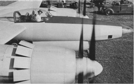
The Hughes XF-11 experimental twin-engined, twin-boom photo-reconnaissance aircraft, which had contrarotating propellers, crashed on its maiden flight, seriously injuring Hughes. The XF 11 was a candidate for a military contract. On July 7,1946, Hughes took his XF 11 reconnaissance airplane on its first flight. Though photographed in the plane just before the test, he intended the flight to be secret. The contra-rotating props developed problems, and the plane crashed, seriously injuring Hughes. Full power. Release brakes. Rolling. Lifting off. Climbing. Everything perfect. Power reduction. Right props slip into reverse pitch. Fierce asymmetric thrust (one second). Feathering in-op (two seconds). Try to hold heading (three seconds). Back on right, full power on left (four seconds). No good, back on both (five seconds). Crash. On April 15, 1947, Hughes successfully test flew a second version of the XF 11, this one with single rotation airscrews, and personally conducted most of the test program.
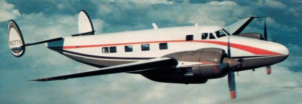
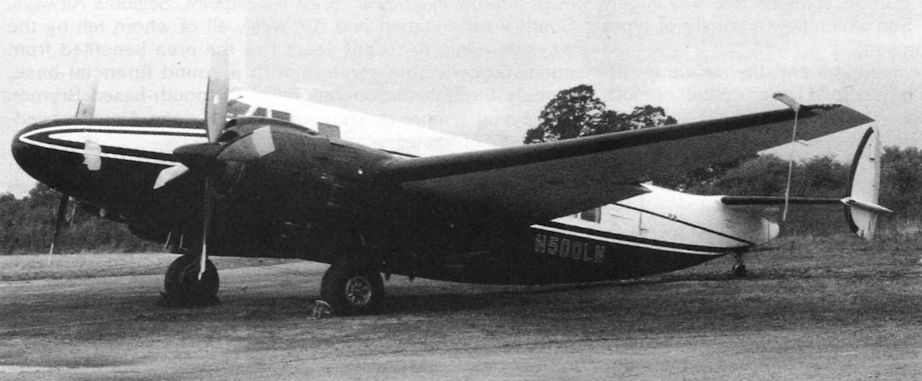
The business aviation community wanted a vehicle that was fast, far reaching, pressurized and new. Dee Howard had the answer the Howard 500. By 1959, Howard was flying his prototype of the 500, a larger aircraft that was based upon the PV 1 but had a redesigned fuselage and a 25% larger wing area. Howard’s 500 featured pressurization 6.75 psi; maximum cruising speed of 338 knots; with its 2,500 hp P&W R 2800 CB 17 engines throttled back to 1,100 hp each, the 500 could cruise for more than 8.5 hours and cover about 2,400 nm. But most importantly, the Howard 500 was constructed from new metal. At least the fuselage and the wing centre sections were new; the outboard wing panels were from surplus PV 1’s. The aircraft was granted a new aircraft certificate under the transport category regulations that existed then, on February 20, 1963.
The 10 to 14 passenger 500, with its cabin high enough to accommodate a standing six¬ foot two inch man, had water injection (officially called AD1 for anti detonation injection) and four blade, 11¬ foot diameter props; a 0.45 to one propeller drive re¬duction gear reduced the prop revolutions to less than half the engine’s speed. A two speed supercharger enabled the 34,000 pound Howard to fly up to 35,000 feet, although the maximum certificated ceiling with passengers was 25,000ft. Hydraulically operated rudder boosts lowered the minimum control speed, with one engine inoperative, from nearly 200 knots on the original Navy versions of the PV 1 Ventura to 95 knots. A yaw limiter system, which sensed the aircraft’s yaw angle and provided an electrical signal to the rudder boost system, was necessary to produce the required positive rudder force gradient with increasing yaw angles. Auto feathering assured that any loss of power below a BMEP of 75 psi with the throttle advanced beyond the 45 inch mp position would streamline the blades and eliminate the performance and Vmc penalties. The aircraft’s sole compressor for cabin pressurization was located on the left engine, and it would declutch itself automatically if the right engine failed, thus enabling the left engine to produce maximum power during single engine operations. Production continued through the mid ’60s with twenty two 500s sold.
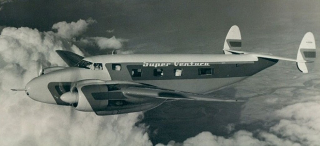
By 1954, Howard had decided that the next step for corporate aircraft (which were mostly Twin Beeches and DC 3s at the time) was faster, farther ranging machines like his modification of the Lockheed PV 1 Ventura. Howard introduced the Super Ventura, which led to development of the Howard 250, the 350, and culminated in the Howard 500.
By 1954, Howard had decided that the next step for corporate aircraft (which were mostly Twin Beeches and DC 3s at the time) was faster, farther ranging machines like his modification of the Lockheed PV 1 Ventura. Howard introduced the Super Ventura, which led to development of the Howard 250, the 350, and culminated in the Howard 500.
By 1954, Howard had decided that the next step for corporate aircraft (which were mostly Twin Beeches and DC 3s at the time) was faster, farther ranging machines like his modification of the Lockheed PV 1 Ventura. Howard introduced the Super Ventura, which led to development of the Howard 250, the 350, and culminated in the Howard 500.
In 1964 Business AirCraft Corp (successor to Howard Areo) announced sale of the first BA 400 pressurised Super Ventura. It cruised at 350 mph at 21,000 ft with a useful load of 10,100 lb. It was the only pressurised plane in production available for $550,000.
In 1943, Reichsmarschall Göring issued a request for design proposals to produce a bomber that was capable of carrying a 1,000 kilograms (2,200 lb) load over 1,000 kilometres (620 mi) at 1,000 kilometres per hour (620 mph); the so-called “3×1000 project”. Conventional German bombers could reach Allied command centers in Great Britain, but were suffering devastating losses from Allied fighters. At the time, there was no way to meet these goals—the new Junkers Jumo 004B turbojets could provide the required speed, but had excessive fuel consumption.
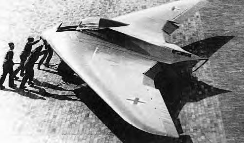
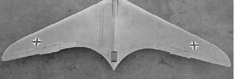
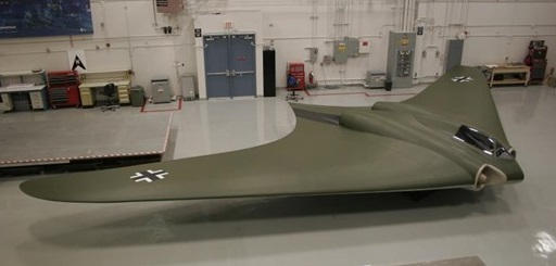
The Hortens concluded that the low-drag flying wing design could meet all of the goals: by reducing the drag, cruise power could be lowered to the point where the range requirement could be met. They put forward their private project, the H.IX, as the basis for the bomber. The Government Air Ministry (Reichsluftfahrtministerium) approved the Horten proposal, but ordered the addition of two 30 mm cannons, as they felt the aircraft would also be useful as a fighter due to its estimated top speed being significantly higher than that of any Allied aircraft.
Horten IX
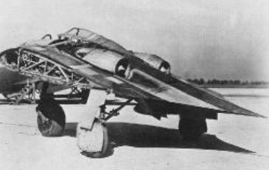
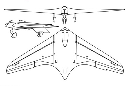
The H.IX was of mixed construction, with the center pod made from welded steel tubing and wing spars built from wood. The wings were made from two thin, carbon-impregnated plywood panels glued together with a charcoal and sawdust mixture. The wing had a single main spar, penetrated by the jet engine inlets, and a secondary spar used for attaching the elevons. It was designed with a 7g load factor and a 1.8× safety rating; therefore, the aircraft had a 12.6g ultimate load rating. The wing’s chord/thickness ratio ranged from 15% at the root to 8% at the wingtips. The aircraft utilized retractable tricycle landing gear, with the nosegear on the first two prototypes sourced from a He 177’s tailwheel system, with the third prototype using an He 177A main gear wheelrim and tire on its custom-designed nosegear strutwork and wheel fork. A drogue parachute slowed the aircraft upon landing. The pilot sat on a primitive ejection seat. A special pressure suit was developed by Dräger. The aircraft was originally designed for the BMW 003 jet engine, but that engine was not quite ready, and the Junkers Jumo 004 engine was substituted.
Control was achieved with elevons and spoilers. The control system included both long-span (inboard) and short-span (outboard) spoilers, with the smaller outboard spoilers activated first. This system gave a smoother and more graceful control of yaw than would a single-spoiler system.
The first two of the type were built at Gottingen.
Four aircraft of the H IX type were started, designated V.1 to V.4.
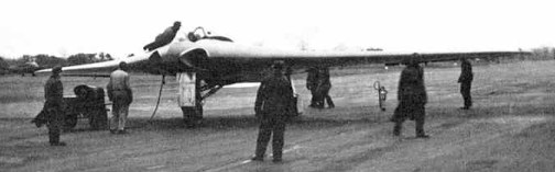
V.1 was the prototype, designed as a single seater with twin B.M.W. 109-003-1 jets, which were not ready when the airframe was finished. It was accordingly completed as a glider with fixed tricycle landing gear and extensively test flown at Oranienburg during the summer of 1944. D.V.L. instrumented it for special directional damping tests to determine its suitability as a gun platform. First flown on 1 March 1944, flight results were very favorable, but there was an accident when the pilot attempted to land without first retracting an instrument-carrying pole extending from the aircraft.
The design was taken from the Horten brothers and given to Gothaer Waggonfabrik. The Gotha team made some changes: they added a simple ejection seat, dramatically changed the undercarriage to enable a higher gross weight, changed the jet engine inlets, and added ducting to air-cool the jet engine’s outer casing to prevent damage to the wooden wing.
Göring believed in the design and ordered a production series of 40 aircraft from Gothaer Waggonfabrik with the RLM designation Ho 229, even though it had not yet taken to the air under jet power. The first flight of the H.IX V2 was made in Oranienburg on 2 February 1945. All subsequent test flights and development were done by Gothaer Waggonfabrik. By this time, the Horten brothers were working on a turbojet-powered design for the Amerika Bomber contract competition and did not attend the first test flight. The test pilot was Leutnant Erwin Ziller. Two further test flights were made between 2 and 18 February 1945. Another test pilot used in the evaluation was Heinz Scheidhauer (de).
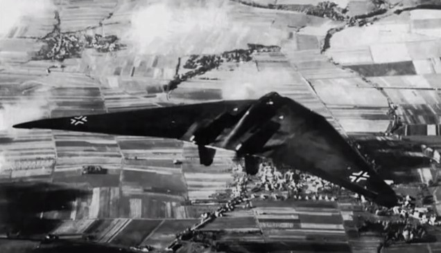
The H.IX V2 reportedly displayed very good handling qualities, with only moderate lateral instability (a typical deficiency of tailless aircraft). While the second flight was equally successful, the undercarriage was damaged by a heavy landing caused by Ziller deploying the brake parachute too early during his landing approach. There are reports that during one of these test flights, the H.IX V2 undertook a simulated “dog-fight” with a Messerschmitt Me 262, the first operational jet fighter, and that the H.IX V2 outperformed the Me 262. Two weeks later, on 18 February 1945, disaster struck during the third test flight. Ziller took off without any problems to perform a series of flight tests. After about 45 minutes, at an altitude of around 800 m, one of the Jumo 004 turbojet engines developed a problem, caught fire and stopped. Ziller was seen to put the aircraft into a dive and pull up several times in an attempt to restart the engine and save the precious prototype. Ziller undertook a series of 4 complete turns at 20° angle of bank. Ziller did not use his radio or eject from the aircraft. He may already have been unconscious as a result of the fumes from the burning engine. The aircraft crashed just outside the boundary of the airfield. Ziller was thrown from the aircraft on impact and died from his injuries two weeks later. The prototype aircraft was completely destroyed after 2-hours flying.
V.3 was being built by Gotha at Friedrichsrodal as a prototype of the series production version. The V3 was larger than previous prototypes, the shape being modified in various areas, and it was meant to be a template for the pre-production series Ho 229 A-0 day fighters, of which 20 machines had been ordered. The V3 was meant to be powered by two Jumo 004C engines, with 10% greater thrust each than the earlier Jumo 004B production engine used for the Me 262A and Ar 234B, and could carry two MK 108 30 mm cannons in the wing roots.
Work had also started on the two-seat Ho 229 V4 and Ho 229 V5 night-fighter prototypes, the Ho 229 V6 armament test prototype, and the Ho 229 V7 two-seat trainer. The Ho 229 V4 two-seat all-weather fighter, was in construction at Friedrichroda, but not much more than the center-section’s tubular framework completed as was the Ho 229 V5 two-seat all-weather fighter. The Ho 229 V6 projected definitive single-seat fighter version with different cannon, mock-up was in production at Ilmenau.
The Ho 229 A-0 projected expedited production version based on Ho 229 V6 was not built. The H.IXb (also designated V6 and V7 by the Hortens) projected two-seat trainer or night-fighter; not built.
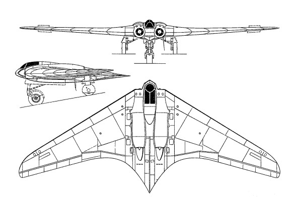
In shape, the H IX was a pure wing with increased chord at the center to give sufficient thickness to house the pilot and the jet units, which were placed close together on either side. The H IX started as a private venture and the Hortens were very anxious to avoid failure so they avoided aerodynamic experiments wherever possible. A lower sweepback was used than on the H V and H VII and laminar flow wing sections were avoided as a potential source of trouble. Wing section at the junction with the center sections was 14% thick with maximum thickness at 30% and 1.8% zero Cmo camber line. At the centerline thickness was increased locally to 16% to house the crew. The tip section was symmetrical and 8% thick. Horten also believed that since the compressibility cosine correction to drag was based on the sweepback of the maximum thickness line, the ordinary section would show little disadvantage. Wing twist was fixed by consideration of the critical Mach number of the underside of the tip section at top speed. This gave a maximum washout of 1.8°. Having fixed this, the CG was located to give trim at CL = 0.3 with elevons neutral. In deciding twist for high speed aircraft, CD values were considered in relation to local CL at operational top speed and altitude (10 km in the case of the H IX). Twist was arranged to give minimum overall drag consistent with trim requirements. The wing planform was designed to give a stall commencing at 0.3 to 0.4 of the semi-span. Wing structure comprised a main spar and one auxiliary spar or wooden construction with ply covering. The center section was built up from welded steel tube. Wing tips were all metal. The undercarriage was completely retractable and of tricycle type the front wheel folding backwards and the main wheels inwards. The nose wheel was castering and centered with a roller cam. When resting on the ground, wing incidence was 7° and the nose wheel took about 40% of the total weight.
The jet engines were installed at -2° to the root chord and exhausted on the upper surface of the wing at 70% back from the nose. To protect the wings the surface was covered with metal plates aft of the jet pipe and cold air bled from the lower surface of the wing by a forward facing duct and introduced between the jet and the wing surface. The installation angle was such that in high speed flight the jest were parallel to the direction of flight. Lateral and longitudinal control was by single stage elevon control flap with 25% Frise nose and compensating geared tap balance. (This system was also used on the H VII, see para. 4.6.) The pilots control column was fitted with a variable hinge point gadget, and by shifting the whole stick up about 2” the mechanical advantage could be doubled on the elevons for high-speed flight. Directional control was by drag rudders. These were in two sections, slight movements of the rudder bar opening the small (outboard) section and giving sufficient control for high speed. At low speeds when courser control was necessary the large movement also opened the second spoiler, which started moving when the small one was fully open. By pressing both feet at once, both sets of spoilers could be operated simultaneously; this was stated to be a good method of steadying the aircraft on a target when aiming guns. The Hortens stated that the spoilers caused no buffeting and claimed an operating force of 1 kg for full rudder, with very little variation in speed. A change was made from the original H VII parallel link system to improve the control force characteristics. With the new system, aerodynamic forces could be closely balanced by correct venting of the spoiler web, leading the main control load to be supplied by a spring. The cover plate of the spoilers was spring loaded to form an effective seal with the rudders closed; this device was used on most Horten spoiler and dive brake designs. On further models of the H IX it was proposed to fit the “trafficator” type rudder tried experimentally on the H VII.
Landing flaps consisted of plain trailing edge flaps (in four sections) on the wings, with a 3% chord lower surface spoiler running right across the center section, which functioned as a glide path control. The outer pair of plain flaps lowered 27° and the inner pair 30° – 35° on the glider version V.1. On V.2 mechanical trouble prevented the inner pair operating and all flying was done with the outer pair only. The center section spoiler could be used as a high speed brake and gave 1/3 g at 950 kph. No dive recovery flap was considered necessary. Proper performance tests were not done on V.2 before its crash and top speed figures were calculated values, checked by Messerschmitts. The following figures were remembered by Reimar Horten: All Up Weight, Including Ammunition and Armour: 8,500 kg (18,700 lbs.) All Up Weight, Excluding Ammunition and Armour: 7,500 kg Wing Area: 52 sq.m (566 sq.ft.) Wing Loading: 33 lb./sq.ft. Fuel (I2 Crude Oil): 2,000 kg (4,400 lbs.) Performance at 7,500 kg (16,500 lbs.) Takeoff Run: 500 m Takeoff Speed (10 deg Flap): 150 kph (95 mph) (Note: This corresponds to a CL of 1.30 which is the stated stalling CL of the aircraft.) Top Speed (at Sea Level): 950 kph (590 mph) (CDo estimated to be 0.011) Calculated ceiling was 16 km (52,000 ft). Engines would not work above 12 km as the burners went out. Rate of Climb at Sea Level: 22 m/sec (4,300 ft/min) In tests against the Me 262 speeds of 650-700 kph (400-430 mph) were obtained on about 2/3 throttle opening. This appears to be the only flight test figure available. Messerschmitt sent performance calculators to the Horten works to check their estimates. The method suggested by D.V.L. for getting the sweepback correction to compressibility drag was to take an area of 0.3 x the root chord squared at the center section as having no correction applied, and then apply full cosine correction over the outer wing. Sweepback angle was defined as that of the quarter chord locus. Test data was available for CDv. for zero sweepback. The Messerschmitt method was to base sweepback on the max t/c locus and to scale Mach number by the square root cos Ø. The H IX V.1 was flown by Walter Horten, Scheidhauer and Ziller. Scheidhauer did most of the flying (30 hours) at Oranienberg, Horten and Ziller flew for about 10 hours. D.V.L. instrumented the aircraft for drag and directional stability measurements. No drag results were obtained because of trouble with the instrument installation – apparently an incidence measuring pole was fitted which could be lowered in flight and glide path angle was obtained from the difference between attitude and incidence measurements. One day they landed without retracting the pole. Directional oscillation tests were completed successfully and an advance report was issued (10 pages of typescript) by Pinsker and Lugner fo D.V.L. The essence of the results was that the lateral oscillation was of abnormally long period – about 8 sec. At 250 kph and damped out in about 5 cycles. At low speeds the oscillation was of “dutch roll” type but at high speed very little banking occurred. Many fierce arguments took place at D.V.L. on desirable directional stability characteristics, the Hortens naturally joining the “long period” school of thought. They claimed that the long period would enable the pilot to damp out any directional swing with rudder and keep perfectly steady for shooting. It was found that by using both drag rudders simultaneously when aiming, the aircraft could be kept very steady with high damping of any residual oscillation. Lateral control was apparently quite good with very little adverse yaw.
Longitudinal control and stability was more like a conventional aircraft than any of the preceding Horten types and there was complete absence of the longitudinal “wiggle” usually produced by flying through gusts. Tuft tests were done to check the stall but the photographs were not good enough for much to be learned. Handling was said to be good at the stall, the aircraft sinking on an even keel. There seems to be some doubt, however, as to whether a full stall had ever taken place since full tests with varying CG and yaw had not been done. Although the stick was pulled hard back, the CG may have been too far forward to give a genuine stall. Directional stability was said by Scheidhauer to be very good, as good as a normal aircraft. He did not discuss this statement in detail as he was obviously very hazy about what he meant by good stability and could give very little precise information about the type and period of the motion compared with normal aircraft. Scheidhauer had flown the Me 163 as a glider and was obviously very impressed with it; he was confident enough to do rolls and loops on his first flight. We asked him how the H IX V.1 compared with the 163; he was reluctant to give an answer and said the two were not comparable because of the difference in size. He finally admitted that he preferred the 163 which was more maneuverable, and a delight to fly (he called it “spielzeug”).
The H IX V.2 with two Junkers 109-004B-1 jet engines was flown at Oranienburg only by Ziller and completed about 2 hours flying before its crash. The redesigned Ho IX V2 demonstrated speeds of up to 960km/h before it was destroyed. This occurred after an engine failure – the pilot undershot, tried to stretch the glide and stalled. One wing must have dropped, for the aircraft went in sideways and Ziller was killed. Before the crash a demonstration had been given against an Me 262; Horten said the H IX proved faster and more maneuverable, with a steeper and faster climb.
In spite of the crash, Horten thought the single engine performance satisfactory and said the close spacing of the jets made single engined flying relatively simple. Such promise encouraged the RLM to instruct Gothaer Waggonfabrik to assume development of the design, and a third prototype, the Go 229 V3, was produced with 1000kg thrust Jumo 109-004C turbojets, but was prevented from flying by the end of hostilities in May 1945.
V3
Work had also started on the two-seat Go 229 V4 and Go 229 V5 night-fighter prototypes, the Go 229 V6 armament test prototype, and the Go 229 V7 two-seat trainer, No progress had been made on 20 pre-production Go 229A-0 fighter-bombers, on order at the end of the war, that were intended to carry two 1000kg bombs and four 30mm MK 103 cannon.
Production was assigned to the Gothaer Waggon Fabrik, which main facilities were placed in the city of Gotha. An initial contract for 20 pre-production aircraft was awarded to the firm and works begun. The Gotha engineers introduced several and extensive modifications to adapt the design to the series production. The construction was subcontracted to the Ortlepp Möbel Fabrik at Friedrichroda. This was a logical solution as the GWF facilities had all their capabilities compromised in the production of parts for other aircraft manufacturers. Besides its management was pushing the RLM to adopt their flying wing designs and this way cancel the Horten IX series production. The Gotha designs were known as the Gotha P-60 with three different versions A, B and C. When the Ortlepp Works at Friedrichsroda were overrun by troops of the American 3rd Army’s VII Corps on April 14, 1945 they found inside of the building three FW in different construction stages: The V3 was nearly complete. The jet engines were installed and most part of the works on the skin had finished.
After the end of the war, the V4 and V5 disappeared. In some reports they are briefly mentioned but it’s quite likely that they were scrapped. The V1, the non-powered prototype, was also destroyed and last seen at Kassel Rothwesten airfield. We do not know where in Europe the V3 was taken, where it was crated and loaded in a ship. According to the NASM the HMS Reaper packing list is not known, but there were other vessels with war booty that left Europe. What is sure is that the V3 was shipped to the USA and arrived by train to Freeman. Today, the Horten IX V3 is in store at the Garber Building 22 awaiting a restoration.
Ho-IX V2 Engine: 2 x 2 x Jumo-004, 900kg Take-off weight: 6900 kg / 15212 lb Empty weight: 4844 kg / 10679 lb Wingspan: 16.76 m / 55 ft 1 in Length: 7.46 m / 24 ft 5.75 in Height: 2.6 m / 8 ft 6 in Wing area: 52.8 sq.m / 568.33 sq ft Max. speed: 960 km/h / 597 mph Crew: 1
Horten Ho 229A / V3 manufacturer’s estimates Powerplant: 2 × Junkers Jumo 004B turbojet, 8.7 kN (1,956 lbf) each Wingspan: 16.76 m (55 ft 0 in) Wing area: 50.20 m² (540.35 ft²) Length: 7.47 m (24 ft 6 in) Height: 2.81 m (9 ft 2 in) Empty weight: 4,600 kg (10,141 lb) Loaded weight: 6,912 kg (15,238 lb) Max. takeoff weight: 8,100 kg (17,857 lb) Maximum speed: 977 km/h (estimated) (607 mph) at 12,000 metres (39,000 ft) Service ceiling: 16,000 m (estimated) (52,000 ft) Rate of climb: 22 m/s (estimated) (4,330 ft/min) Wing loading: 137.7 kg/m² (28.2 lb/ft²) Thrust/weight: 0.26 Armament: 2 × 30 mm MK 108 cannon Bombload: 2 × 500 kilograms (1,100 lb) bombs / R4M rockets Crew: 1
Go 229A 0 Engines: two 1000 kg (2,205 lb) thrust Junkers Jumo 109 004C turbojets. Maximum speed 1000kph (621mph) at 6100 m (20,015 ft) Landing speed 130 kph (81 mph) Maximum take off weight: 8500 kg (18.739 lb) Wingspan 16.78 m (55 ft 5/8 in) Length 7.47 m (24 ft 6 1/8 in) Wing area: 51.5sq.m (554.36 sq.ft). Armament: four 30 mm MK 103 cannon and up to 2000 kg (4,409 lb) of bombs.