The first Kawasaki Ki 96 fighter prototype flew in 1943. 3 built.
Ki-96 Engines: 2 x Mitsubishi Ha-112-II, 1125kW Wingspan: 15.57 m / 51 ft 1 in Length: 11.45 m / 37 ft 7 in Height: 3.7 m / 12 ft 2 in Wing area: 34 sq.m / 365.97 sq ft Max take-off weight: 6000 kg / 13228 lb Empty weight: 4550 kg / 10031 lb Max. speed: 600 km/h / 373 mph Ceiling: 11500 m / 37750 ft Range: 1600 km / 994 miles Armament: 1 x 37mm cannon, 2 x 20mm cannons Crew: 1
The first Ki 66 dive bomber prototype flew in October 1942. Did not entered production.
Ki-66 Engines: 2 x Nakajima Ha-115, 850kW Wingspan: 15.5 m / 50 ft 10 in Length: 11.2 m / 36 ft 9 in Height: 3.7 m / 12 ft 2 in Wing area: 34.0 sq.m / 365.97 sq ft Max take-off weight: 5750 kg / 12677 lb Empty weight: 4100 kg / 9039 lb Max. speed: 535 km/h / 332 mph Ceiling: 10000 m / 32800 ft Range: 2000 km / 1243 miles Armament: 2 x 12.7mm machine-guns, 2 x 7.7mm machine-guns, 300-500kg of bombs Crew: 2
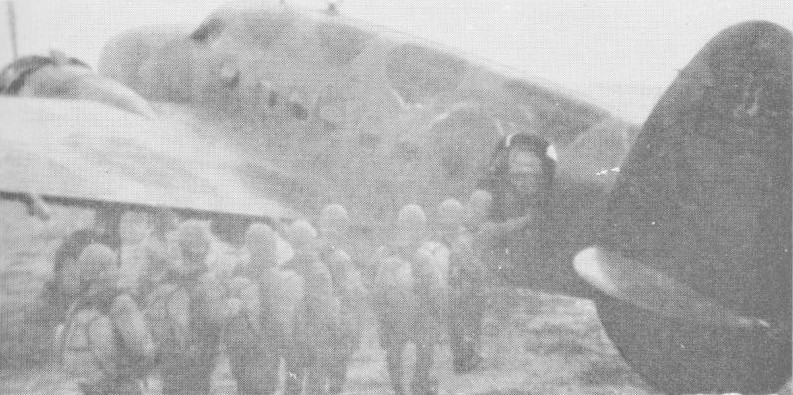
Developed from the Lockheed 14 transport built by the Kawasaki Company under licence, the Ki-56 had an enlarged fuselage with a large freight loading door in the port rear-fuselage side. Powered by two 671kW Ha-26-II radial engines, two prototypes were followed by 119 series-built machines designated Army Type 1 Freight Transport (assembled between 1941 and 1943).
56 were manufactured for the army by Kawasaki before production was handed over to Tachikawa who built a further 688.
Widely used in the Pacific war, the Ki-56 was coded Thalia by the Allies.
Engines: 2 x Nakajima Ha-25, 740kW / 990 hp Take-off weight: 8025 kg / 17692 lb Empty weight: 4895 kg / 10792 lb Wingspan: 19.96 m / 64 ft 6 in Length: 14.9 m / 48 ft 11 in Height: 3.6 m / 11 ft 10 in Wing area: 51.2 sq.m / 551.11 sq ft Max. speed: 400 km/h / 249 mph at 11,155 ft Ceiling: 8000 m / 26250 ft
In 1937, at the beginning of the Sino Japanese war, Chinese air force units were equipped with twin engined Soviet Tupolev SB 2 bombers. The Japanese army air staff, impressed by the high performance of the Soviet aircraft, instructed the Kawasaki company in December 1937 to produce a twin engined bomber. It was to be powered by two Nakajima Ha 25 radial engines and to be able to fly at a maximum 480 km/h (298 mph) at 3000 m (9850 ft), and cruise at 350 km/h (217 mph) at the same altitude. It had also to reach 5000 m (16 400 ft) in ten minutes and carry a 400 kg (880 lb) bombload. At that time army strategy was based on a war with the USSR, so it was further stipulated that the aircraft must be capable of operating under Siberian winter conditions.
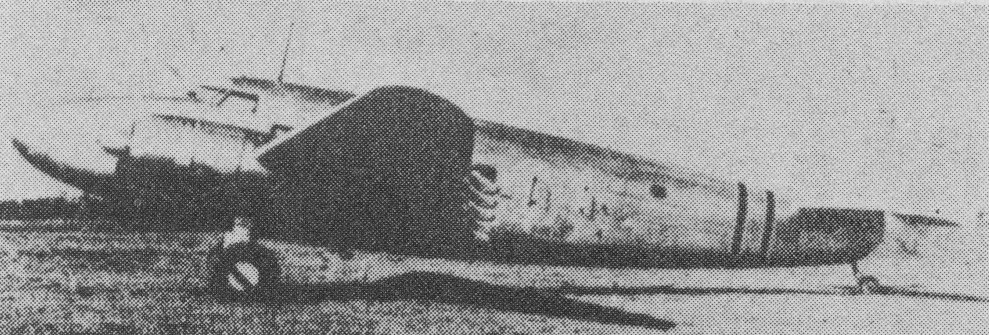
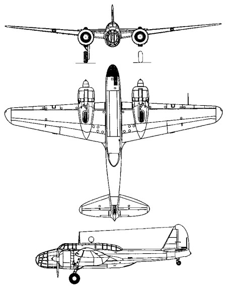
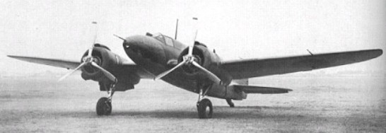
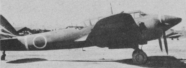
Takeo Doi began design work in January 1938. The Ki 48 was a mid wing all metal cantilever monoplane, the wing position being adopted to provide an internal bomb bay. The fuselage was cut down aft of the dorsal gunner’s cockpit and the ventral gunner’s stepped position. The bomb aimer/nose gunner’s position was fully glazed. There was a single curved fin and rudder, and the main undercarriage legs retracted backwards to lie fully enclosed in the engine nacelles. In the type’s prototype form, two 708kW Nakajima Ha-25 radial engines mounted in nacelles at the wing leading edges.
Takeo Doi’s design team was forced to divide its time between the extremely complex Ki 45 Kai fighter and the Ki 48. Consequently the first Ki 48 did not fly until July 1939. Three more prototypes and five evaluation machines were soon completed. During development, tail flutter problems were overcome and the rear fuselage strengthened. The new type met a favourable reception and series production started late in 1939, under the designation Army Type 99 Twin engined Light Bomber. All the criteria laid down by the army had been met except that the bomb bay only accommodated 300 kg (660 lb) of bombs.
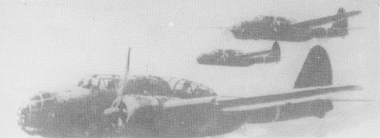
Ki 48 Ia aircraft first went into action in northern China with the 45th Sentai and did well against indifferent Chinese opposition. They were used at night, as well as for short-range daylight operations. The Ki-48 Ib was only slightly modified, and a total of 557 of both initial versions were built up to June 1942. With the Japanese attack on the United States and the British Empire, Ki 48s were deployed in Burma, Malaya and the Philippines, moving on with the advancing land forces into the Dutch East Indies and New Guinea. After a few months their defects became obvious: there was minimal protection for crew and fuel, and despite the Ki-48’s good speed the better Allied fighters could outstrip it and had little trouble dealing with its defensive armament of single 7.7 mm (0.303 in) Type 89 machine guns flexibly mounted in nose, dorsal and ventral positions. Night raids became the rule.
Three Ki 48 II prototypes were built by February 1942, powered by twin 1150 hp Nakajima Ha 115 radials and outwardly resembling the Ki 48A. They had a slightly lengthened fuselage and had fuel tank protection in addition to armour plating for the crew positions. Production aircraft also featured further fuselage strengthening. Ki 48 IIb was a dive bomber variant with fence type under-wing dive brakes. Late production machines had dorsal fin extensions to improve stability. The maximum bombload was increased to 800 kg (1764 lb). Maximum speed rose by 24 km/h (15 mph).
Ki-48
During the fighting over New Guinea, large numbers of Ki 48s, codenamed Lily by the Allies, were destroyed on the ground. The Ki 48 remained in production until October 1944. The late versions were designated Ki- 48 IIc and had a 12.7 mm (0.5 in) Type 1 machine gun in the dorsal position in place of the previous rifle calibre weapon, in addition to one more nose mounted 7.7 mm Type 89 gun. The Ki 48 II fought against odds in the Philippines and over Okinawa in day and night operations. A specially modified suicide version, Ki 48 II Kai, carried an unchanged bombload, its bombs being triggered on impact by a nose probe. Ki 48s were used for tests of the Igo Ib guided missile and the Ne0 turbojet unit.
The total of all variants built 1977.
The Air to Surface Guided Missile was called I-Go Type1-Otsu or Ki-148. At the Ki-148 test, it struck an Onsen hotel. At last Ki-148 was complete.
Some of the Ki.48-IIb featured a small dorsal extension to the fin.
A number of Ki.48s were modified for experimental duties, one becoming a testbed for a ramjet engine.
Ki 48 I Engines: 2 x Nakajima Ha 25, 950 hp Span: 17.47 m (57 ft 4 in) Length: 12.60 m (41 ft 4 in) Height: 3.80 m / 12 ft 6 in Wing area: 40 sq.m / 430.56 sq ft Empty weight: 4050 kg Gross weight: 5900 kg (13000 lb) Maximum speed: 480 km/h (298 mph) Range: 2400 km Service ceiling: 9500 m Crew: 4 Armament: 4 x 7.7mm mg or 3 x 7.92mm mg Bomb load: 300-400 kg
Ki-48-II Engines: 2 x Nakajima Ha115 (1,130hp) Length: 12.75m Wing Span: 17.47m Height: 4.32m Wing Area: 40.0 sq.m All-Up Weight: 6,750Kg Empty Weight: 4,550Kg Max Speed: 505Km/h Range: 2,400Km Service Ceiling: 10,000m Crew: 4 Armament: 7.92mm Machine Gun X 4 Bomb load: 300 or 500Kg
Ki.48-IIa Engines: 2 x Mitsubishi Ha.115, 1150 hp Span: 57 ft 3.75 in Max speed: 314 mph at 18,372 ft
Ki-48-IIb Engines: 2 x Nakajima Ha-115, 850kW Max take-off weight: 6500-6750 kg / 14330 – 14881 lb Empty weight: 4550 kg / 10031 lb Wingspan: 17.45 m / 57 ft 3 in Length: 12.75 m / 41 ft 10 in Height: 3.80 m / 12 ft 6 in Wing area: 40 sq.m / 430.56 sq ft Max. speed: 505 km/h / 314 mph Ceiling: 10100 m / 33150 ft Range: 2050 km / 1274 miles Range w/max.fuel: 2400 km / 1491 miles Armament: 3 x 7.7mm machine-guns, 400kg of bombs Crew: 4
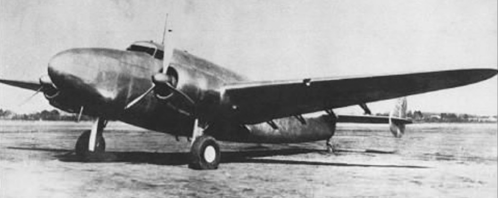
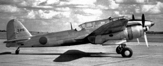
Developed as a result of an official specification issued in March 1937, this two seat twin engined fighter did not go into service until August 1942. The intervening five years saw strenuous development and testing interspersed with periods of total inactivity caused by the Japanese army’s equivocal attitude to the type of fighter typified by the German Bf 110.
The original requirement was for a fighter capable of 540 km/h (335 mph) at 3500 m (11480 ft), and able to operate at altitudes between 2000 m (6660 ft) and 5000 m (16400 ft). It was to have a range of some 1800 km (1100 miles) and the selected engines were 820 hp Nakajima Ha 20b radials. Engineer Takeo Doi struggled with the difficult concept, and the first prototype was ready to fly in January 1939.
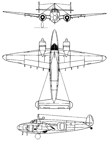
The Ki.45 origins can be traced back to the Ki.38 design produced by Kawasaki at the JAAF’s requed in 1937, althought so many modifications were called for by the Army that the revised design was re-titled Ki-45.
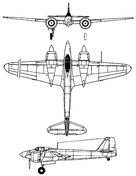
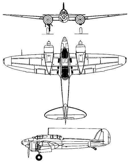
The first Kawasaki Ki-45 Toryu (dragon killer) prototype was a cantilever mid-wing monoplane with retractable tailwheel landing gear. A slender fuselage provided enclosed accommodation for two in tandem. Armament was heavier than originally specified: a forward-firing 20 mm (0.79 in) Ho 3 cannon and two 7.7 mm (0.303 in) Type 89 machine guns were fixed to fire forward, and there was a flexibly mounted rear 7.7 mm Type 89 machine gun. There was also provision to carry two drop tanks or two 250kg bombs on underwing racks. As flight trials continued, the Ki 45 was found to achieve a rather poor performance and the engines continually gave trouble. The third prototype featured major refinements. Drag was considerably reduced, but maximum speed was still only 480 km/h (298 mph). There was some instability and a tendency to nacelle stall. Yet the Ki 45 prototypes were externally attractive, with curved, oval fuselages and elliptical wings and tail surfaces. The main undercarriage legs retracted backwards into the engine nacelles leaving the wheels partially exposed. At first, the undercarriage retraction mechanism was hand operated, but an electrically operated mechanism was installed on the third prototype.
With so many difficulties and no pressing need for the type, the army suspended further flight trials, leaving six further prototypes partly finished. Six months later, in April 1940, work was restarted, and 1000 hp Nakajima Ha 25 14 cylinder double row radials were installed in one of the airframes, which was completed the following July. The five other airframes were similarly modified, and two more machines were built from scratch. A maximum speed of 520 km/h (323 mph) at 3500 m (11500 ft) was attained.
The design team had meanwhile been reviewing the whole project and proposed that the Ki 45 Kai of simplified design was suited for mass production. The army accepted the proposal, and the first of three Ki 45 Kai prototypes flew in May 1941.
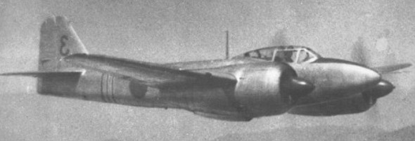
Twelve pre-production aircraft followed. With tests successfully completed, Ki-45 KAIa series production as the Army Type 2 Two seat Fighter began early in September 1941, and soon the Ki-45 Kai was given the popular name Toryti (dragon slayer) while the Allies called it Nick. Effective crew and fuel tank protection was incorporated in the design. Power was provided by two 1050 hp Nakajima Ha 25 radials, but late production Model B aircraft had Mitsubishi Ha 120s.
Model A, the first series version, went to the 5th Sentai in Japan in August 1942. The next Sentais to equip with the type were the 16th in China and the 21st in Burma. It was effective in attacks on enemy shipping and troop concentrations, a specialized attack version being built as Ki-45 KAIb Model B. Original armament had comprised two 12.7 mm (0.5¬in) Type 1 machine guns in the nose, one forward firing 20 mm (0.79 in) Ho 5 cannon in a ventral tunnel in the starboard nose section, and a single 7.92 mm (0.312 in) Type 98 machine gun on a flexible mounting operated by the observer. In the Model B a 37 mm (1.46 in) Type 98 cannon was installed in the ventral tunnel and the nose guns were replaced by a single 20 mm Ho 3 cannon.
A number of alternative weapon installations were tried experimentally, including the use of a 75mm cannon for attacks on shipping.
Production aircraft had straight contoured fuselage and wings. The range of Model A was 2260 km, (1400 miles) and it could climb to 5000 m (16 400 ft) in just over six minutes. Models A and B flew operationally in many theatres of war, not least in the New Guinea region, where they inflicted heavy losses on US motor torpedo boats.
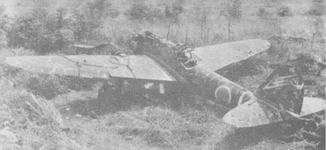
The Ki-45 KAIa was, for its day, heavily armed and proved effective against the USAF’s Consoldiated B-24 Liberators and, when these bombers were used more extensively for night operations, the Ki-45 was adapted to attack them. Thus the night-fighting capability of the type was discovered, leading to development of the Ki-45 KAIc night-fighter.
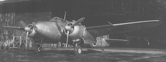
It was not until 1944 that the night-fighter version, the Ki-45 KAIc, became operational as the only army night-fighter of the war. Retaining the two 805kW Mitsubishi Ha-102 radials of the Ki-45 KAIb heavy day fighter, the Ki-45 KAIc was armed with a single forward-firing semi-automatic 37mm Ho 203 Type 98 cannon in a fairing under the fuselage, two oblique/upward-firing 20mm Ho-5 cannon in the centre fuselage, and a single hand-held machine-gun in the rear cockpit. It had been intended to fit airborne radar in the nose, and therefore no nose guns were included. Production difficulties seriously delayed the radar equipment and it did not enter service, although a single aircraft flew with centimetric radar shortly before the end of the war. Production of the Ki-45 KAIc got underway at Kawasaki’s Akashi plant in March 1944, the first aircraft being completed the following month. By then Kawasaki had transferred Ki 45 Kai manufacture from its Gifu plant to the works at Akashi.
On 15 June American Boeing B-29s of XX Bomber Command launched their first raid on the Japanese homeland, and were intercepted by eight Toryus whose pilots shot down eight of the big bombers. At that time about 40 Ki-45 KAIc fighters had been completed, and the aircraft went on to serve with the 4th Sentai at Usuki in the Oita prefecture, the 5th Sentai at Usuki and Komachi in the Aichi prefecture, the 53rd Sentai at Matsudo in the Chiba prefecture, and the 70th Sentai at Kashiwa. Toryus shared the night defence of Japan with the navy’s J1N1-S and Yokosuka P1Y1-S, and were probably the most successful in action against the massive American raids in the last six months of the war; the 4th Sentai alone was credited with 150 kills, of which 26 were gained by one pilot, Captain Isamu Kashiide, all despite the lack of any AI radar. Away from the homeland Ki-45 KAIc nightfighters also served with the 45th Sentai in the Philippines and New Guinea late in 1944, and with the 71st Dokuritsu Hiko Chutai at Singapore in August 1945. Production of the Ki-45 KAIc reached 477 aircraft before being terminated in December 1944. The type was codenamed ‘Nick’ by the Allies.
An improved model, with uprated engined, was begun in 1942 under the designation Ki.45-II, subsequently developed into the Ki.96 heavy fighter, which was eventually abandoned although components of it were later utilised in the Ki.102.
Total production, including original Ki 45 prototypes, and evaluation aircraft, was 1701, including 477 Model Cs.
Major Revisions:
Ki-45 Prototype 1 Nakajima Ha-20b Engine Two 7.7 mm Type 89 machine guns mounted in the upper fuselage nose 20 mm Ho-3 cannon mounted in a ventral tunnel One flexible rear-firing 7.7mm Type 89 machine-gun 298 mph @ 13,125 ft
Experimental Improved Type 1 Ki-45 Ha-25 fourteen-cylinder double-row radials with single stage superchangers. 323 mph @ 11,480 ft
Ki-45 KAI – Type 2 Slimmer fuselage with straight contours and redesinged tail surfaces Straight tapered wing of increased span and area New engine nacelles of smaller diameter mounted lower on the wings Replacement of the 7.7 mm type 89 machine-guns by two 12.7 mm Type 1 (Ho-103) machine guns in the nose and one flexible rear firing7.9mm Type 98 machine-gun Replacement of the telescopic gunsight by a reflector gunsight. 340 mph at 22,965 ft
Ki-45 KAIa Slimmer fuselage with straight contours and redesinged tail surfaces Straight tapered wing of increased span and area New engine nacelles of smaller diameter mounted lower on the wings Replacement of the 7.7 mm type 89 machine-guns by two 12.7 mm Type 1 (Ho-103) machine guns in the nose and one flexible rear firing7.9mm Type 98 machine-gun Replacement of the telescopic gunsight by a reflector gunsight. 340 mph at 22,965 ft
Ki-45 KAIb Ground attack modifications made Forward-firing armament was revised to include one 20mm Ho-3 cannon mounted centrally in the nose One hand-loaded 37mm Type 98 cannon in the ventral tunnel Late production b’s were powered by a pair of 1050 hp Army Type 101 fourteen-cylinder radials. Note: Some of these aircraft were modified in the filed by replaceing the upper fuselage petrol tank with a pair of 12.7mm Type 1 machine-guns mounted obliquely to fire upward.
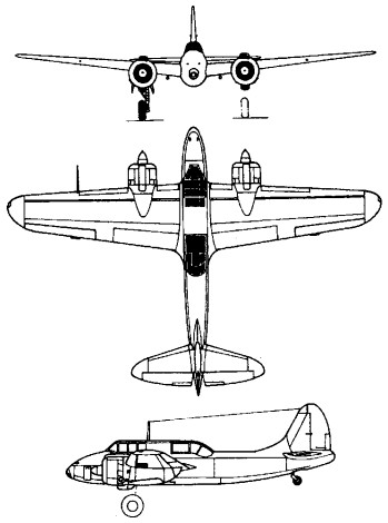
Ki-45 KAIc Engines: 2 x Mitsubishi Ha-102 Type I, 1080 hp Wingspan: 49 ft 5.25 in Length: 36 ft 1 in Height: 12 ft 1.75 in Empty weight: 8818 lb Loaded weight; 12,125 lb Max speed: 340 mph at 22,965 ft Service ceiling: 32,810 ft Semi-automatic 37mm Ho-203 cannon in the ventral tunnel Two obliquely-mounted upward 20 mm Ho-5 cannon in the center fuselage Crew: 2
Ki-45 KAId Anti-shipping version Two 20 mm Ho-5 cannon in the nose One 37 mm Ho-203 cannon in the ventral tunnel One flexible 7.9 mm Type 98 machine-gun in the rear cockpit Ki-45 KAIc airframe
Ki-45 KAI-II (Never produced, changed to the Ki-96) 1500 hp Mitsubishi Ha-112-II
Production:
Gifu Plant 3 Ki-45 Prototypes Jan – May 1939 8 Improved Type 1 Ki-45 Prototypes July 1940 – Feb 1941 3 Ki-45 KAI prototypes Auguest- October 1941 12 Ki-45 KAI pre-production aircraft October – December 1941 305 Ki-45 KAIa and KAIb production aircraft January 1942 – September 1943
Akashi Plant 893 Ki-45 KAIa, b & d production aircraft September 1942 – July 1945 477 Ki-45 KAIc production aircraft April – December 1944
Specifications
Ki.45-KAI-Ko Engines: 2 x 1080hp Mitsubishi Ha-102 Wing Span: 15.05m Length: 11.00m Height: 3.70m Wing Area: 32sq.m Empty Weight: Max.Weight: Speed: 540km/h Ceiling: 10730m Range: 2260km Armament: 1 x 20mm, 2 x mg12.7mm, 1 x mg7.92mm Crew: 2
Model A Span: 15.02 m (49tt 3 in) Length: 10.6 m (34 ft 9 in) Gross weight: 5276 kg (11632 lb) Maximum speed: 547 km/h (340 mph)
Model B Span:15.02 m (49 ft 3 in) Length: 111 m (36 ft 1 in) Gross weight. 5500 kg (12125 lb)
Kawasaki Ki 45 KAIc ‘Nick’ Engines Two Nakajima Ha-102 nine-cylinder radials, 810kW Wingspan: 15.02 m / 49 ft 3 in Length: 11 m / 36 ft 1 in Height: 3.7 m / 12 ft 2 in Wing area: 32 sq.m / 344.44 sq ft Max take-off weight: 5500 kg / 12125 lb Empty weight: 4000 kg / 8819 lb Maximum speed 540 km/h / 336 mph Operating altitude 6,560 ft to 16,405ft Ceiling: 10000 m / 32800 ft Range: 2000 km / 1243 miles Endurance 4 hours & 40 minutes at 217 m/hr Armament: 1 x 37mm cannon, 2 x 20mm cannons, 1 x 7.92mm machine-guns, 2 x 250kg bombs Crew: 2
The Ka-226 as a derivative of the Ka-26, has gas turbine engines, installation of new, aerodynamically more perfect, rotors, arrangement of new on-board avionics package and provision for comfortable conditions for the pilot and passengers. The Ka-226 has a coaxial rotor scheme with two three-blade rotors of 13-m diameter. The polymeric composite blade with advanced aerodynamic profile is semi-rigidly attached to the hub by a torsion bar. The helicopter features modular design (detachable transport-passenger cabin) and four-leg non-retractable landing gear. The helicopter is equipped with up-to-date on-board equipment package and complies with the national aviation standards, as well as FAR requirements, categories A and B. The Ka-226 was announced at the 1990 Helicopter Association International convention, Dallas, USA, and developed originally for the Russian TsENTROSPAS disaster relief ministry, which provided significant funding. First flown (RA-00199), at Lyubertsy, on 3 September 1997, the “official” first flight was on the following day. The prototype flew four sorties by 31 December 1997, and began AP-29 certification testing on 28 March 2001. State ground testing of Ka-226 second prototype was completed at Strela’s Orenburg plant on 6 March 2000. KAPP built two prototypes, of which the first was rolled out at Kumertau on 29 May 1998. The first production aircraft from KAPP was due to have flown in the first quarter of 2002 but remained under construction in mid-2002. Planned certification in third quarter of 2002 was not achieved, being reportedly “seriously delayed”. The prototype was destroyed in ground resonance incident in November 2002.
Named Sergei in 1999, honouring politician Sergei Shoigu, the programme was also guided by Sukhoi General Designer, Sergei Mikheev. By mid-2000, Moscow regional government had provided Rb 12 million in development funding and was beginning disbursements under second programme valued at Rb4 million. Initial deliveries due in first half of 2000, but not effected. Prototypes built jointly by Kamov, Strela, KAPP and Ufa Motors, with final assembly by KAPP and Strela for production aircraft.
Strela scheduled to have delivered five preproduction helicopters to Kamov at Lyubertsy by mid-2000; these for MChS Rossii but not supplied until 2003, when one exhibited at MAKS ’03. KAPP designated second production plant; first batch of five under construction by 2001. Motor-Sich of Zaporozhye, Ukraine, negotiated with Kamov in June 2000 to build Ka-226s powered by indigenous ZMKB AI-450 engine; agreement on AI-450 installation signed 15 August 2001. On 19 October 2001, however, Motor Sich announced it would source all Ka-226 components with Ukrainian industry, if decision to proceed were taken. Programme launch was reportedly imminent in late 2002. MoU on use of Turbomeca Arrius 2G signed in August 2001 with NPO Saturn and French manufacturer; collaboration agreement followed on 16 April 2002, with intention of certifying Arrius Ka-226 in September 2004 after trials of three prototypes. Orders by January 2002 totalled 66: Gazprom 50, Moscow City 10, TsENTROSPAS five and Bashkiriya one. Identified requirements include up to 20 for City of Moscow for patrol and medevac; some 250 for MChS Rossii/TsENTROSPAS disaster relief organisation; and up to 75 for Gazprom in gasfield support role. Firm order for 25 reportedly received from TsENTROSPAS by 1997, but quantity had reduced to 10 by 1999; by mid-2000 this quoted as five firm (to be first five production aircraft) and further 15 to be ordered by 2002; manufacture by Strela which had completed first two (including one in medevac configuration) by early 2002. Bashkiriyan local government ordered one Ka-226-50 in September 2001; this accepted 28 December 2001 (when still not cleared for flight) and due for trials at Zhukovsky before service entry. Funds for 22 of initial Gazprom order for 50 had been transferred by 2001, this initial batch, built by Strela, to have been received by 2005 (although formal signing of order for 50 was undertaken at Moscow Salon in August 2001). Moscow city government signed US$1.5 million order for 10 in December 2001, delivery over two years, but later announcement indicated that funds had not been earmarked; Moscow’s helicopters to be built by KAPP. City allocated initial Rb33 million in 2002 and intends to receive three helicopters in 2003, four in 2004 and final three in 2005. Ka-226 was beaten by Kazan Ansat in competition to supply new training helicopter to Russian armed forces, announced September 2001, although small number of Ka-226s required by Russian Navy. To 1999, development cost was Rb108 million. Featuring interchangeable mission pods. Refinements of the Ka-26/126 include a new rotor system with hingeless hubs and glass fibre/carbon fibre blades, changes to the shape of the nose, twin tailfins and rudders. Payload modules include an agricultural systems with a hopper capacity of 1,000 litres.
The Ka-226 features contrarotating coaxial three-blade rotors, a hinge rotor head with ‘rake’-type blade attachment, the Ka-26 blades of the initial series were to be succeeded by GFRP and CFRP blades with twin-contour spar, load-carrying rear section and electrothermal anti-icing. A rotor brake WAS standard, and non-folding blades. There was a three-stage gearbox with planetary gear trains, of alloy steel and aluminium casting, flange mounted with four load-carrying bolts. Accessories included cooling fan, hydraulic pump and AC generator. The engine input was 6,000 rpm. The flying controls were mechanical with irreversible hydraulic actuators. An automatic rotor constant-speed control, with a conventional four-channel control (longitudinal, lateral, cyclic and differential pitch). The two endplate fins and rudders are toed inward 15 degrees, with a non-controllable horizontal stabiliser. Airframe materials are primarily aluminium alloys, steel alloys and composite sandwich panels of GFRP with honeycomb filler. Rotor blade overhaul interval 2,000 hours; total life 6,000 hours, but to be extended by increments to 18,000 hours. The landing gear is a non-retractable four-wheel type. Main units, at rear, are carried by stub-wings. All four units embody oleo-pneumatic shock-absorber, the forward wheels have no brakes. The rear wheels have pneumatic brakes. Mainwheel tyres size 595 x 185 mm, pressure 2.5 bars + 1.0; forward wheel tyres size 300 x 125 mm, pressure 3.43 bars. Skis optional. Provision for large inflatable pontoons, across front of aircraft forward of front wheels and under each mainwheel. Forward units of castoring type, without brakes. Rear wheels have pneumatic brakes.
Two 335kW Rolls-Royce 250- C20R/2 turboshafts are side by side aft of rotor mast, with individual driveshafts to the rotor gearbox. Two 335kW Rolls-Royce 250-C20B engines were in the prototypes. The transmission rating is 626kW. Alternatively, two Progress (ZMKB) AI-450 turboshafts, each 331kW or two Turbomeca Arrius 2G (500 kW) or Klimov VK-800 turboshafts (588kW) may be fitted. Standard fuel capacity is 770 litres, in tanks above and forward of the payload module area. Provision for two external tanks, on sides of fuselage, has a total capacity of 320 litres.
The fully enclosed cabin has a rearward-sliding door each side, and normal operation is by a single pilot. A second seat and dual controls are optional. The cabin is ventilated, and warmed and demisted by air from a combustion heater, which also heats the passenger cabin when fitted. An air filter is fitted on the nose of the agricultural version. Space aft of cabin, between main landing gear legs and under transmission, can accommodate a variety of interchangeable payloads. A cargo/passenger pod accommodates four or six persons on folding sidewall seats, with provision for a seventh passenger beside pilot. Two clamshell doors are at the rear of the pod, with emergency exit each side and a hatch in the floor. An ambulance pod accommodates two stretcher patients, two seated casualties and a medical attendant. For agricultural work, a chemical hopper (capacity 1,000 litres) and dust spreader or spraybars are fitted in this position, on the aircraft’s CG. Flight deck pressurisation protects crew against chemical ingress. The aircraft can also be operated with either an open platform for hauling freight or hook for slinging loads at the end of a cable or in a cargo net. A single hydraulic system, with manual override, is for control actuators. The main electrical system is 27V 3kW DC, with a back-up 40Ah battery. A secondary system is 36/115V AC with two static inverters, and a 115/200V AC system with 16kVA generator (6kVA to power agricultural equipment and rotor anti-icing). Electrothermal rotor blade de-icing; hot air engine air intake anti-icing; alcohol windscreen anti-icing; electrically heated pitot. Pneumatic system for mainwheel brakes, tyre inflation, agricultural equipment control, pressure 39 to 49 bars.
The cost in 2000 for the Ka-226A was US$1.5 million.
The Ka-226-50 is an “improved” version.
Engine: 2 x Allison 250-C20B. Instant pwr: 313 kW. Rotor dia: 13 m. Fuselage length: 8.1m Height: 4.15m MTOW: 3400 kg Payload: 1300 kg Useful load: 1448 kg Max speed: 111 kts Max cruise: 104 kts Max range: 602 km HIGE: 6623 ft HOGE: 4197 ft Rate of climb: 11.7m/s Endurance: 4.6h Service ceiling: 16,557 ft Crew: 1 Pax: 7
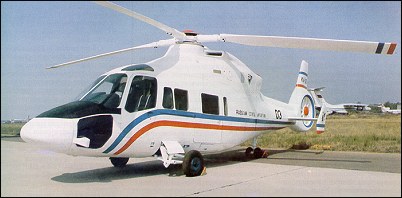
Funded under the Russian programme for development of civil aviation for 2000, construction of the prototype Ka-62 (then known as V-62) began early 1990, but apparently was abandoned. One Ka-60 military version and two Ka-62s were intended to undertake flight trials, although the second of the basic type was completed as a Ka-60U, delaying the debut of the civil version. In April 2001, The Turkish Ministry of Public Health was discussing a contract for six Ka-62s, with a total value of US$31.5 million. The Russian government’s 2002-10 aviation plan included Rb62 million to develop the Ka-62 and Rb51 million to launch production at UUAP and, possibly, RSK “MiG” (LAPIK).
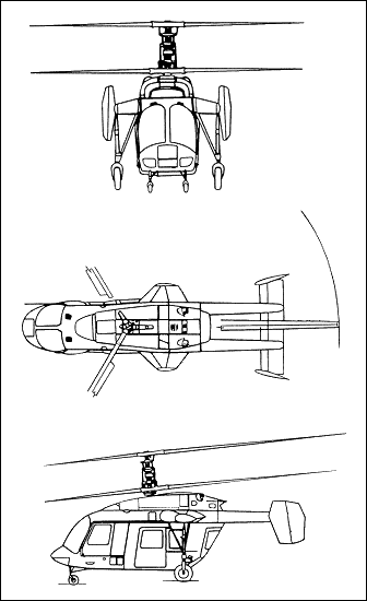
The Ka-62 was developed on the basis of the Ka-60 army helicopter and is intended for carrying passengers and cargo in the transport cabin, and transportation of bulky cargo on external sling. It has a single main rotor with a multi-blade tail rotor in the tail ring. The rotor blades and 60% of the airframe weight are made of polymeric composite materials. The airframe features perfect aerodynamic outlines, large transport-passenger cabin and retractable three-leg landing gear. The power plant is made of modular-design developed by Rybinsk Motor Design Bureau, headed by Mr. A. Novikov, Designer General. The civil derivative has large door openings on both fuselage sides of the cabin. The helicopter is equipped with anti-icing and fire-fighting systems. The Ka-62 is equipped with standard avionics suite of a basic transport version for VFR conditions, or for IFR flying, using the satellite navigational equipment. The export version of the helicopter is supplied with western engines and avionics of the customer’s option.
Originated as a military transport, all main systems and components are duplicated, with main and secondaries routed on opposite sides of airframe. The transmission is resistant to 12.7mm bullets and main blades to 23mm shells. The gearboxes have a run-dry capacity. The main rotor blades have sweptback tips. Yaw control is by 11-blade fan-in-fin. Landing gear is retractable tricycle tailwheel. Composites account for 60%, by weight, of the structure, including blades of main rotor, fuselage sides, doors, floor and roof, tailboom, fin, vertical stabilisers, and fan blades of carbon-reinforced Kevlar.
Retractable reverse tricycle type; Single KT-217 mainwheels retract inward and upward into the bottom of the fuselage and twin rear wheels retract forward into the tailboom. Shock absorbers are in each unit. An option is inflatable pontoons for emergency use on water. The basic Ka-62 has two RKBM Rybinsk RD-600V turboshafts, each 956kW max continuous, 1,140kW emergency rating. Fuel tanks are under the floor, with a 1,450 litres capacity. General Electric T700/ CT7-2D1 engines are offered as an alternative to the RD-600V. The crew of one or two, side by side, have an optional bulkhead divider between the flight deck and the cabin. The cabin holds up to 14 passengers in four rows. A forward-hinged door is on each side of the flight deck, and a large forward-sliding door and small rearward-hinged door are on each side of the cabin. There is a baggage hold to the rear of the cabin. The interior is heated and air conditioned. A thermoelectric de-icing system is optional. An Ivchenko AI-9V APU was originally proposed, but a replacement Aerosila TA-14 was under development.
Ka-62 Passengers: 16 Engines: 2 x Rybinsk RD-600 turboshaft, 955kW Main rotor diameter: 13.5m Fuselage length: 13.25m Height: 4.1m Max take-off weight: 6250kg Empty weight: 3730kg Max speed: 162 kts Cruising speed: 140 kts Rate of climb: 11.7m/s HIGE: 9508 ft. HOGE: 6885 ft. Service ceiling: 5000m / 16,885 ft. Range: 720km Payload: 2000-2500kg Crew: 1-2 Pax: 14
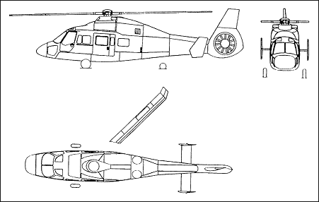
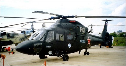
The original coaxial rotor, twin tail, single-engined V-60 won the Soviet Army lightweight helicopter and Mi-8 replacement competition against the twin-engined Mil Mi-36 in 1982. Subsequently the design was considerably modified to achieve greater speed through adoption of a single five-blade main rotor of 13.5-m diameter and Fenestron-type tail rotor with eleven blades. The polymeric composite blade is attached to the hub by a torsion bar. The airframe features large door openings on both fuselage sides, retractable three-leg energy-absorbing landing gear. The seats of the crew and the troopers are energy attenuating seats. The pilot-in-command is on the right-hand seat. The power plant of the helicopter is two modular-design engines developed by Rybinsk Motor Design Bureau, headed by Mr. A. Novikov, Designer General. Particular attention is paid to the increased combat survivability means of the helicopter. All principal systems and units of Ka-60 are duplicated and separated. The composite polymeric materials that make about 60% of the helicopter structural weight add to the survivability of the helicopter being more resistant to the combat damages. The foam polyurethane that filled the tanks prevents the danger of the fuel explosion. The basic avionics suite for all versions is the one for transport assault helicopter. This suite ensures operational missions in daytime and night, in VFR and IFR conditions. All main systems and components are duplicated, with main and secondaries routed on opposite sides of airframe. The transmission is resistant to 12.7mm bullets, the main blades to 23mm shells. The gearboxes will run without oil. The main rotors are advanced technology with sweptback tips. Production versions were to have a slower-turning five-blade rotor. Undercarriage is a reverse tricycle. The Ka-60 has IR- and radar-absorbent coatings. Accommodation is for up to 16 infantry troops or six stretchers and three attendants. The pilot (starboard) and co-pilot/gunner (port) sit side by side. There is provision for dual controls, with the control stick top common with the Ka-50/52. The cockpit has a three-screen EFIS. Avionics include a Pastel RWR and Otklik laser warning system, and an Arbalet MMW radar with an antenna in the nose. The Ka-60 is fitted with a cargo hook. Armament can be carried on a one-piece transverse boom through the cabin, to the rear of the doors, to provide suspension for total of two B-8V-7 seven-round 80mm rocket pods, two 7.62mm or 12.7mm gun pods, or similar armament. The prototype has RKBM Rybinsk RD-600V Turboshafts, as the Ka-62, but the production engine was to be the 1,103kW Klimov VK-1500. RRTM RTM322 or GE CT7 were available in the export versions.
The first flight was originally due 1993, but the programme was slowed by funding shortages, and the priority changed to promotion of a civil variant (the Ka-62). The Ka-60 was officially revealed at Lyubertsy on 29 July 1997, when the prototype was close to completion. The first (601) flew on 10 December 1998, made a second sortie on 21 December, and the first official flight on 24 December. All were hovering flights. The international debut was at MAKS ’99, Moscow, in August 1999. The first ‘forward flight’ was on 24 December 1999. Further testing was intermittent, due to irregular Ministry of Defence funding, but production versions of the RD-600V turboshaft were installed in mid-2002. At this time, it was stated only that the prototype had completed “several” flights, although State Trials were not due to begin until early 2003. Conflicting reports quote both Arsenyev and Ulan Ude as prospective production lines. However, LMZ (later LAPIK, part of RSK “MiG”) was reported in April 2000 to be preparing for production and in mid-2001 was building second prototype, which to be completed as a trainer in Ka-60U configuration. This entered final assembly in July 2002, although RD-600 engines became due to have been received late 2002. Displayed (marked as 602) at MAKS ‘03, Moscow, August 2003. Series production at LAPIK was due to begin in 2003. The Ka-60U cost US$1.7 million in 2000. In August 2002, it was announced that power plant was to be changed to Klimov VK-1500 to increase participation by RSK “MiG” group. A smaller variant of Ka-60 was reported in mid-2001 to have been offered to Russian Navy.
Versions: Ka-60U – Pilot and aircrew training Ka-60K – Utility, shipborne over-the-horizon targeting Ka-60R – Reconnaissance
Ka-60 Crew: 1-2 Engine: 2 x Rybinsk RD-600 turboshaft, 975kW Main rotor diameter: 13.5m Max take-off weight: 6500kg Max speed: 300km/h Cruising speed: 265km/h Hovering ceiling: 2100m Service ceiling: 5150m Range: 700km Payload: 2000-2750kg
The Ka-50-2 designation applies to three different aircraft. The basic Ka-50-2 is a variant of the Ka-50 single-seater, though the designation is also applied to two twin-seat aircraft; first of these was a version of the Ka-52 Alligator. All Ka-50-2s differ from the baseline Ka-52 in retaining the attack and anti-tank role using 12 laser beam-riding AT-8 Vikhr ATGMs or 16 Rafael NT-D ATGMs. Number 024 was used as demonstrator.
The second variant of Ka-50-2 is another two-seater, intended to have a conventional stepped, tandem cockpits. A further subvariant of the tandem-seat Ka-50-2, the Erdogan (Turkish for Born Fighter) was proposed to Turkey jointly by Kamov and Israel Aircraft Industries. Powered by TV3- 117VMA-02 engines, this would have been fitted with longer-span wings and feature a NATO-compatible Giat 621 turret containing a single 20mm cannon which would fold down below the belly of the helicopter in flight, for a 360 degree arc of fire. It would fold to starboard for landing, and could be fired directly forward, even when folded. Ten Turkish pilots flew Alligator “061” at Antalya, Turkey, in early 1999 as part of evaluation process for a requirement for 145. Named as second choice when the Bell AH-1Z selected, negotiations reopened in mid-2002, following an impasse in negotiations with USA.
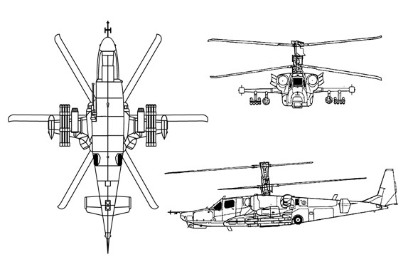
The multi-role all-weather combat Ka-52 “Alligator” coaxial-type helicopter differs from its predecessor by a wider nose part and twin-seat crew cockpit where the pilot ejection seats are arranged side-by-side. Both pilots have full controls of the helicopter without any limitations. The pilot cockpit is armored. Numerous weapons options for the helicopter are achieved by arranging a movable high-speed firing gun starboard of the helicopter, and by six external wing stores. The avionics suite is comprised of a multiplexed, multi-level digital computer-based system having large storage capacity and high speed. Observation, search and targeting systems comprising head-mounted display are used for round-the-clock and all-weather detection of specified targets and their attack using optical, TV, laser, IR and radar equipment. NATO reporting name Hokum-B, the Ka-52 was revealed at the 1995 Paris Air Show, rolled out in December 1996. The first flight was on 25 June 1997, but the first official flight was on 1 July 1997. The Ka-52 is 85% similar to the single-seat Ka-50, but the front fuselage is redesigned to accommodate two crew, side by side. Access is by upward-hinged and bulged gull-wing type transparent canopy doors over each seat. The bottom of nose is recessed on the starboard side to improve the field of fire of the 2A42 gun. Some cockpit armour and a number of rounds for the cannon are omitted to compensate for the increased weight. Power plant for the production models is two uprated 1,863kW Klimov TV3-117VMA-SB3 turboshafts. Two 1,633kW TV3-117VMA turboshafts powered the prototype. The pilot and pupil or navigator/weapons operator have Zvezda K-37-800 ejection systems, for simultaneous emergency escape, similar to that of Ka-50. Full dual controls are standard including two colour and two monochrome SMD 66 multifunction displays. AVIONICS: Integrated by Sextant Avionique, supplier of head-down displays, the Navigation and Attack System for Helicopters (NASH), Topowl helmet-mounted sight display, Nadir 10 navigation system. Radar: Phazotron FH-01 Arbalet MMW radar installed in mast-mounted dome. Flight: Nadir 10 nav system with Stratus laser gyro AHRS and Doppler radar. Instrumentation: Arsenal Shchel-V helmet-mounted sight for weapons operator. Mission: Samshit-E weapons control system above and behind the second cockpit, with TV, FLIR and laser range-finder and target designator. Thomson-CSF FLIR (or optional Russian Khod FLIR) integrated with Shkval electro-optical (TV) sighting system in ball above fuselage aft of canopy. Smaller ball for optical sight under fuselage. Windows for laser range-finder and IR camera in nose turret. Self-defence: Active IR and electronic jamming units; UV-26 flare/chaff dispensers in wingtip fairings. Warning equipment includes Pastel (L150) RWR, Mak (L136) IR and Otklik (L140) laser system.
The Kamov Ka-52 entered series production on October 29, 2008. With deliveries of the first batch of 12 units for the Russian air forcé.
Powered by TV3-117VMA turboshafts of 2,195 unit shp from Kamov the Ka-52 reaches a maximum speed of 310 km/h and a cruise of 270 km/h, able to move backwards up to a maximum speed of 90 km/h or 80 km. /h to the sides. The normal takeoff is around 10,400 kg, the maximum 11,000 kg.
The Ka-52 Kamov cockpit chose the side-by-side seating. Both have a K-37-800 ejection seat which, prior to the exit of the seats, different explosive charges separate the rotor blades to allow both seats come out of the fuselage without inconvenience. The cabin is armored with the capacity to resist impacts of up to 20 mm while the windshields have a resistance to ammunition shots of up to 12.7 mm.
The instrument panel incorporates four multifunction polychrome LCD screens and another two monochrome to which is added an ILS-31 model Head Up Display. Both crew members have GEO-ONV-1 or ONV-1-01 night vision goggles, the entire instrument panel being compatible with them. Within the NAV/COM systems there is an inertial navigator with satellite assistance and digital communications equipment.
The integrated self-defense system known as Vitebsk includes: L-150 Pastel radar warning system L-140 OTKLIK laser warning system Missile approach detector of unknown model Double infrared jammer L-3705 Six UV-26 decoy dispersers
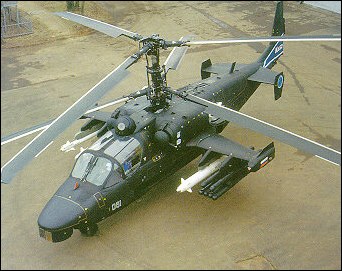
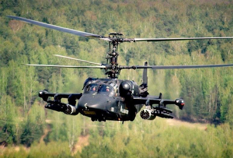
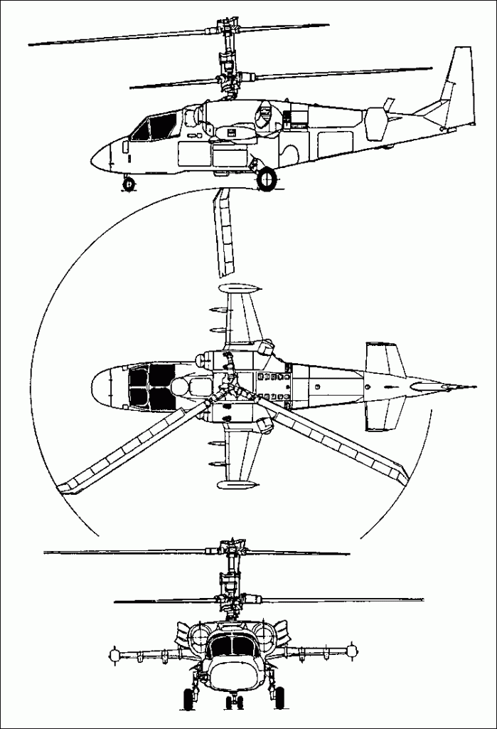
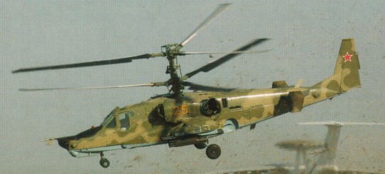
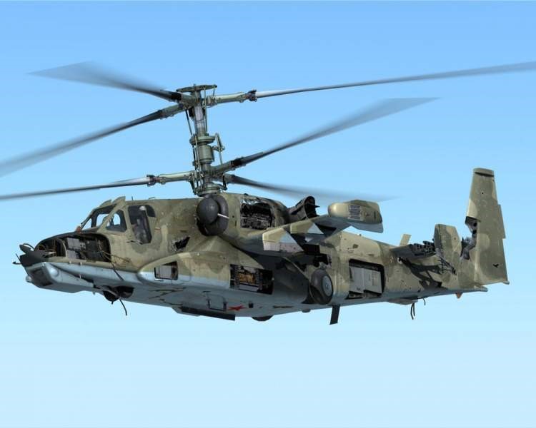
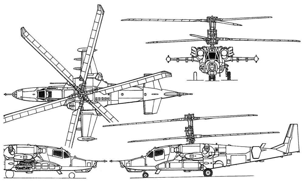
The Ka-50 Akula (Black Shark) is a single-seat attack helicopter. The Ka-50 has two coaxial three-blade rotors of 14.5-m diameter each. The polymeric composite blades are attached to the hub by a torsion bar. The airframe features mid-set stub wing, retractable three-leg landing gear and empennage of a fixed-wing aircraft type. The pilot cockpit is fully armored. The emergency pilot escape system, comprising an ejection seat, operating within the entire flight speed and altitude range. The load factor of 3.5G allows numerous weapons options by arranging a movable high-speed firing gun starboard of the helicopter, and six external wing stores. Total weight of the weapons on the wing stores is 2300kg. The on-board avionics suite uses satellite navigational and the observation, search and sighting systems comprising TV, laser and IR equipment.
A single-seat close support helicopter, the Ka-50 features a coaxial, contrarotating and widely separated semi-rigid three-blade rotors system with swept blade tip, attached to the hub by steel plates. The fuselage has nose sensors, a flat-screen cockpit, heavily armoured by combined steel/aluminium armour and spaced aluminium plates, with a rearview mirror above the windscreen. A sweptback tailfin has an inset rudder and large tab. A high-set tailplane on rear fuselage has endplate auxiliary fins. With retractable landing gear and mid-set unswept wings, carrying ECM pods at tips and four underwing weapon pylons. The engines are above the wingroots. Partially dismantled, the Ka-50 can be air-ferried in the Il-76 freighter. Much of the fuselage skin is formed by large hinged door panels, providing access to interior equipment from ground level.
The fuselage is built around a steel torsion box beam, of 1.0m square section. The wing centre-section passes through the beam, and the cockpit is mounted at the front of beam, gearbox above and engines to the sides. Carbon-based composites materials constitute 35% by weight of the structure, including the rotors. Approximately 350kg of armour protects the pilot, engines, fuel system and ammunition bay. The canopy and windscreen panels are 55mm thick bulletproof glass. The hydraulically retractable tricycle type landing gear has a twin-wheel steerable nose unit and single mainwheels all semi-exposed when up. All wheels retract rearward, and have low-pressure tyres.
Power is from two 1,633kW Klimov TV3- 117VMA turboshafts with VR-80 main reduction gearbox and two PVR-800 intermediate gearboxes, with air intake dust filters and exhaust heat suppressors. Two primary fuel tanks, filled with reticulated foam, are inside the fuselage box beam. Total internal capacity approximately 1,800 litres. The front tank feeds the port engine, the rear feeds the starboard and APU. Each tank is protected by layers of natural rubber. There is provision for four 500 litre underwing auxiliary fuel tanks. Transmission remains operable for 30 minutes after oil system failure. The double-wall steel armoured cockpit is able to protect pilots from hits by 20 and 23mm gunfire over ranges as close as 100m. The interior is black-painted for use with NVGs. Specially designed Zvezda K-37-800 ejection system, for safe ejection from 100m. Following explosive separation of the rotor blades and opening of the cockpit roof, the pilot is extracted from the cockpit by a rocket; alternatively, he can jettison doors and stores before rolling out of cockpit sideways. All systems are configured for operational deployment away from base for up to 12 days without need for maintenance ground equipment. Refuelling, avionics and weapon servicing are performed from ground level. AI-9V APU for engine starting, and ground supply of hydraulic and electrical power, in top of centre-fuselage. Anti-icing system for engine air intakes, rotors, AoA and yaw sensors; de-icing of windscreen and canopy by liquid spray. PrPNK Rubikon (L-041) piloting, navigation and sighting system based on five computers: four Orbita BLVM-20-751 s for combat and navigation displays and target designation, plus one BCVM-80-30201 for WCS. Incorporates PNK-800 Radian navigation system, with C-061K pitch and heading data, IK-VSP-VI-2 speed and altitude and PA-4-3 automatic position plotting subsystems. Series 3 Tester U3 flight data recorder. Ekran BITE and warning system. KKO-VK-LP oxygen system with 2 litre supply for 90 minutes. Electrical supply from two 400kW generators at 115V 400Hz three-phase AC; 500W converter; rectifiers for 27V DC supply. NATO code name ‘Hokum’, the project was launched in December 1977 as the V-80 (Vertolyet 80: Helicopter 80). The first prototype (010) was built by the Kamov bureau and hovered at Lyubertsy on 17 June 1982, and flew on 23 July 1982. Power was by TV3-117V engines. The second prototype (011) flew on 16 August 1983 with TV3-117VMA engines and a mockup of the Shkval tracking system, Merkury LLLTV, cannon and K-041 sighting system. Both prototypes wore painted ‘windows’ to simulate fictitious rear cockpits. Initially reported in the West in mid-1984, but the first photograph did not appear (US Department of Defense’s Soviet Military Power) until 1989. The first prototype was lost in a fatal accident on 3 April 1985. The first was replaced by the third prototype (012) with Mercury LLTV system for the state comparative test programme against the Mil Mi-28, which was completed in August 1986. Two preproduction V-80Sh-1s (014 and 015) were the first to be built at Arsenyev and introduced UV 26 chaff/flare dispensers. The second had the K-37-800 ejection system and mockup of an LLLTV in an articulated turret. Ordered into production in December 1987, a further three were used for continued development work comprising 018 (first flown at Arsenyev 22 May 1991), 020 “Werewolf” and 021 “Black Shark”. (The export marketing name was originally Werewolf, but had changed to Black Shark by 1996.) State tests of the Ka-50 began in mid-1991 and the type was commissioned into the Russian Army Aviation in August 1993 for trials at the 4th Army Aviation Training Centre, Torzhok. In August 1994, the Ka-50 was included in the Russian Army inventory by Presidential decree, and judged winner of the fly-off against Mi-28. The Mi-28 was nominally terminated on 5 October 1994 but the competition continued. Further army evaluation followed when the first two of four production Ka-50s were funded in 1994 and officially accepted on 28 August 1995. The third and fourth were received in 1996, the four were numbered 20 to 23 (prompting pre-series 021 to be renumbered 024 to avoid confusion). Arsenyev production was to have increased to one per month during 1997, but this did not occur. The original Ka-50 (and rival Mi-28A) were overtaken by the issue of a revised requirement which emphasised night capability – favouring the two-seat Mi-28. The initial order for 15 Ka-50s was reportedly cancelled in September 1998, with procurement postponed until 2003. Three were deployed to Mozdok during 1999 for use in Chechnya, but were not used operationally. Two returned to the theatre in December 2000, with the first firing of weapons against guerrilla forces on 6 January 2001 (operating in conjunction with Mil Mi-24s). The helicopters returned to Torzhok in March 2001. Unspecified modifications, found necessary as a consequence of operational deployment, had been incorporated by November 2002, according to a Kamov announcement.
Customers were the four for Russian Army service trials, plus eight flying prototype and pre-series helicopters; all delivered. A further 10 were ordered in the 1997 budget and six in 1998, of which first three were due for delivery before the end of 1998. The initial helicopter was eventually completed in June 1999, two more were due by mid-2000. By early 2003, it was still unclear if helicopters from the first batch of 10 had been delivered to Army Aviation. Two operational Ka-50s were shown at the Moscow Salon in August 2001 but may have been repainted trials aircraft. One army helicopter lost in accident 17 June 1998; attributed to rotor clash. The unit price of the Ka-50N was quoted as between US$12 million and US$15 million in mid-1999.
The Ka-50N (Nochnoy: Nocturnal) was also reported as the Ka-50Sh. A night-capable attack version, essentially a single-seat Ka-52, the programme began in 1993, originally based on TpSPO-V and Merkury LLLTV systems, which were tested on Ka-50 development aircraft. The Ka-50N was first reported in April 1997 as a conversion of prototype 018 with Thomson-CSF Victor FLIR turret above the nose and Arbalet (crossbow) mast-mounted radar, plus a second TV screen in cockpit. The FLIR was integrated with Uralskyi Optiko-Mekhanicheskyi Zavod (UOMZ) Samshit-50 (Laurel-50) electro-optic sighting system, incorporating a French IR set. First flight variously reported as 4 March or 5 May 1997. Programmed improvements included replacement of the PA-4-3 paper moving map with digital equivalent. By August 1997, the FLIR turret was repositioned below the nose and the Arbalet was removed. By mid-1998, the IT-23 CRT display was replaced by a TV-109, and the HUD removed and replaced by Marconi helmet display. A proposed new cockpit was shown in September 1998, having two Russkaya Avionika 203 x 152mm LCDs and central CRT for sensor imagery. Indigenous avionics were intended for any local production orders, the French systems were an interim solution and standard for export. The Republic of Korea Army evaluated both the Ka-50N and the baseline Ka-50. In 1999, pre-production aircraft 014 was exhibited with a UOMZ GOES sensor turret in place of Shkval.
The Ka-50 Hokum-A was a a single seat helicopter, althougth Israeli Air Industries developed a tandem-seat cockpit version with Kamov known as the Ka-52 Alligator or Hokum-B.
Ka-50 Engine: 2 x Klimov TV3-117VK. Instant pwr: 1642 kW. Rotor dia: 14.5 m. Length with rotors turning: 16.0m Empty weight: 7700kg MTOW: 10,800 kg. Payload: 2500 kg. Max speed: 189 kts / 310km/h Range with max payload: 450km Range with max fuel: 1200km HOGE: 13,115 ft / 4000m Rate of climb: 10.0m/s Crew: 1. ROC: 1500 fpm.