Lockheed L.14 Super Electra / Sky Zephyr / 214 Hudson / 414 Hudson / A-29 / A-29 / PB-1 / AT-18 / Kawasaki Type 1

Hudson

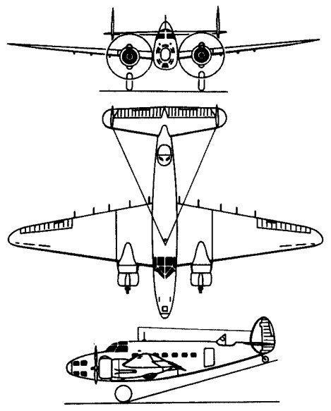
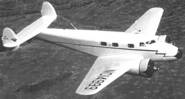
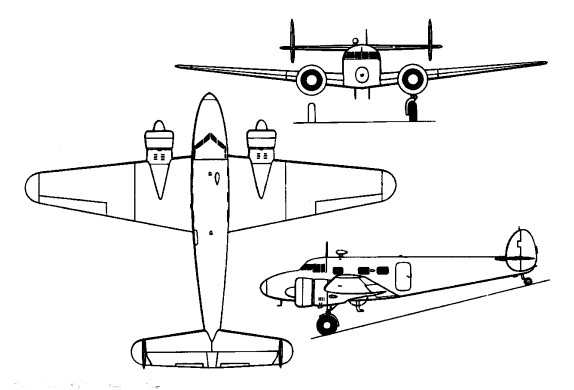
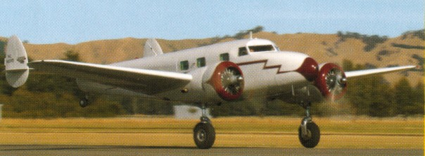
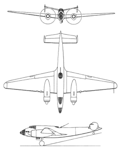
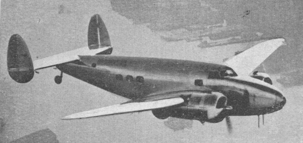
Designed to compete against the DST/ DC-2/DC-3 series being developed by the Douglas company, the Lockheed 14 Super Electra failed to be any significant competition, due to its smaller capacity. Of the same general configuration as the earlier Lockheed 10 Electra, it differed by having a much deeper fuselage accommodating a maximum of 14 passengers, a mid-set wing, and introduced integral fuel tanks in the wing, Fowler-type trailing-edge flaps, fully-feathering propellers and, at a later stage of production, fixed wing slats. These improvements, combined with powerful engines and high wing loading, gave the Super Electra excellent performance but, by comparison with the important and larger-capacity Douglas DC-3, it was less efficient in operation.

Lockheed Hudson Article

First flown in prototype form on 29 July 1937 powered by two 760hp Wright Cyclone radial engines, and certificated on 15 November 1937, initial deliveries were made shortly afterwards.

Howard Huges and 4 crew flew around the world in 3 days 19 hr 14 min in Lockheed 14 New York World’s Fair 1939.

A British Purchasing Commission visited the United States in April 1938, intent on acquiring a substantial number of American military aircraft. Lockheed executives and designers got together when they knew the British team was on its way looking for warplanes and in ten days and nights drawings were produced, and a wooden mock up constructed, of the Model 14 in its converted form of a reconnaissance bomber.

Suitably impressed Lockheed officials met Air Ministry chiefs in London, and on June 23, 1938, a contract was signed for the building of 175 aircraft, with as many more as could be delivered by December 1939, up to a maximum of 250. By the end of 1941 the order had gone up to 1700.

Named Hudson for RAF service, the first example (N7205) made its initial flight on December 10, 1938. Despite problems with tooling, the 250th machine was rolled out at Burbank over seven weeks ahead of schedule, thanks to staff increases and three shift working.

Initially Hudsons were delivered crated aboard ship, the first arriving at Liverpool Docks on February 15,1939, and then assembled at nearby Speke airport, where Lockheed established a subsidiary firm to undertake the rapidly increasing work consequential to the numbers of Hudsons arriving. By the summer of 1940, this amounted to over 200 aircraft. A British installation, when the Hudsons arrived, was a Boulton & Paul power operated dorsal gun turret housing two .303 in Browning machine guns.

On Sunday 8 October 1939: During a patrol flight over the North Sea, a Lockheed Hudson coastal reconnaissance plane of 224 Sqn became the first English aircraft to shoot down a German plane, a Dornier Do.18 flying boat.

In November 1940, because Britain needed aircraft urgently, seven Hudsons were flown from Newfoundland to Ireland. This led to the founding of the Atlantic Ferry Service. Pilots were flown from Britain to Newfoundland. There each of them obtained a new aircraft and flew it to Britain. By Christmas Eve 1943 1000 had been ferried across the Atlantic.

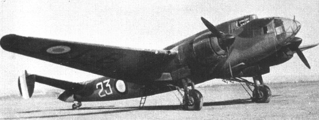
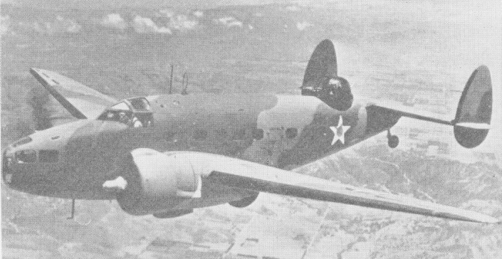
Main differences to the civil passenger version was the glazed nose position, dorsal turret and the bomb bay within the centre fuselage. In addition to the dorsal turret armament, Hudsons carried twin .303 in Browning guns fixed to fire forward from the top of the forward fuselage, and provision for two Vickers ‘K’ guns, one each side in beam positions. On earlier models the bomb load was 750 lb, but later variants were capable of carrying up to 1,400 lbs of bombs or depth charges.

The Hudson I was powered by two 745.2kW Wright GR-1820-G102A Cyclone engines driving Hamilton-Standard two-position propellers. It first entered service with Coastal Command, RAF in mid-1939. The British order for 250 Mk Is was increased to 350, followed by a contract for 20 Mk IIs with Hamilton-Standard Hydromatic constant-speed propellers, 414 Mk IIIs following.

The Hudson III represented the first major revision, having 1,200hp / 894kW GR-1820-G205A Cyclone engines with Hydromatic propellers and a retractable rear-firing ventral gun position. Large numbers of the Hudson III were delivered to the RAF under Lease-Lend (resulting in the use of the USAAF designation A-29) with 894kW Wright R-1820-87 Cyclone engines. Like earlier Hudsons, the Mk III was basically a maritime-patrol bomber and reconnaissance aircraft, but A-29A were fitted with benches for troop carrying. A-29/29A were also used by the USAAF and by the US Navy (as PBO-1).

The Hudson III armament consisted of a maximum bomb load of 1,600lb (726kg) comprising four 250lb (113kg) and six 100lb (45kg) bombs; two fixed Browning 0.303in machine guns in upper nose with 500rpg; one optional Vickers 0.303in machine gun in retractable ventral hatch with 500 rounds; two optional Vickers 0.303in beam machine guns in rear fuselage with 500rpg; two Browning 0.303in machine guns in dorsal Boulton Paul turret with 1,000rpg.

Initially the Mk IIIs had little advantage in range, but after some 150 had been built, extra fuel tanks were fitted, and on November 11, 1940, seven Hudson Mk IIIs flew direct from Gander, Newfoundland, to Aldergrove, Northern Ireland, in 10.5 hours. From then on all Hudsons were flown across the Atlantic on their delivery flights.

One Hudson Mk III was presented to the RAF free, the materials for this aircraft (T9465) having been supplied by Lockheed ‘gratis’ while employees gave their time free. This particular aeroplane was named Spirit of Lockheed Vega Employees, and was handed over to the British Ambassador in front of assembled Lockheed staff. This machine was allotted to 269 Squadron.

At the end of January 1940, Hudsons were the first aircraft in RAF Coastal Command to be fitted with air to surface vessel (ASV) radar, which was to prove so effective against sub¬marines when trying to locate them at night and in bad weather.

Hudsons also flew top secret Scrutator flights between Britain and Sweden. These operations involved taking items of freight, mail and often passengers to Stockholm, while on the return flights, the supply of Swedish ball bearings, made to a very high standard and vital to British war production, was maintained. Passengers were also flown back from Sweden diplomats, escaped Allied prisoners of war and even people who had managed to escape from the clutches of the Gestapo.

Hudsons used on Scrutator were specially converted Mk IIIs and came under the control of BOAC and, although camouflaged, carried civil registrations coming under the BOAC Loch class. Four Hudsons flew this crossing.

The Hudson III was the first aeroplane to be fitted to carry the British-developed Mk I airborne lifeboat. This lifeboat was first used operationally in May 1943 by an RAF air/sea-rescue squadron to rescue the crew of a downed bomber in the North Sea.

In RAF service the Hudson Mk III was followed by the Mk IIIA, first type to be sent under the Lend Lease scheme.

The Hudson IV was produced for the RAAF, with the ventral gun removed but received a D/F loop aerial in a transparent blister. The Air Corps assigned the A-28 designation to a contract for 52 aircraft to be delivered to the Royal Australian Air Force. Although U.S. serial numbers were given to the A-28s, none entered service with the U.S. Army Air Corps. All were delivered to the RAAF under the designation Hudson Mk.IVA and given RAAF serial numbers A16-101 to A16-152.

Thirty Hudson Mk IVs were diverted to the RAF from an Australian contract, followed by 309 Mk Vs and 450 Mk VIs, all these variants having 1,200hp Pratt & Whitney R-1830-SC3G Twin Wasp radials. The Hudson V for the RAF had R-1830-S3G4G engines driving Hamilton-Standard two-position propellers and a retractable ventral gun (as fitted to the Mk III).

The final version was the Hudson VI (designated A-28 by the USAAF) which was convertible to troop transport or cargo carrier with the turret removed. An improved version, designated A-28A, was built for export to the British Commonwealth under Lend-Lease agreements.

By 1943 RAF Hudsons were active in the Mediterranean and Middle East areas, having already flown convoy patrols the previous November to help cover the Allied landings in North Africa.

The Royal Australian Air Force received 247 Hudson’s between January 1940 and May 1942 in several versions.

Although 800 were ordered for the RAF, only 382 were delivered, the remainder going to the USAAF as the A 29, while some ended up with the US Navy as PBO-1 patrol bombers operating in the Caribbean area on anti submarine duties, USAAF machines did not usually have the power operated turret, but instead a single .50 in gun was installed on a flexible mounting in an open position with a shield for the gunner’s back. The A 29 could carry a 1,600 lb bomb load, and on July 7, 1942, the German submarine U 701 was attacked and sunk by one of these aircraft. US Navy PBO 1s sank two German U Boats, both during March 1942.

Orders for Hudsons were not only for the RAF, US Army Air Corps, US Navy and Australia, but also the air forces of Canada, New Zealand, and Nationalist China.

A total of 119 was licence-built in Japan by Kawasaki and Tachikawa. These, powered by 671kW Mitsubishi Ha-26-l radial engines, were designated Army Type LO Transport and were later allocated the Allied code name ‘Thelma’. The Japanese army introduced the first cargo transport, the Kawasaki Type 1, in 1941. The aircraft was a military version of the 13 passenger Lockheed 14 airliner and it had a maximum payload of only 3 metric tons.

Thelma

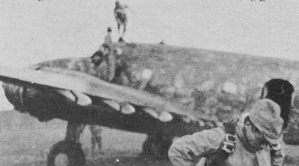
In 1938 Japan used both imported and domestic models as civil freight and mail transport. The civil models were coded ‘Toby, later dropped in favour of Thelma.

Toby

On 14 February 1942, units of the Japanese 38th Division landed on Sumatra north of Palembang, under cover from carrier-based aircraft and a strong cruiser formation under Vice-Admiral Ozawa. Japanese paratroops landed at the same time. At 6.00pm, approximately 70 aircraft of the American Lockheed 14 WG-3 design which had been built under licence before the war by Tachikawa and Kawasaki for the Japanese Army, and given them the name Ro-Shiki, dropped some 700 paratroops on the island. The aircraft had been painted olive green to look like RAF planes, they carried British national emblems and were almost indistinguishable from British Hudson bombers.

The aim of the operation was to seize the Palembang airfields, and above all, two large refinery plants at Pladyu and Sungai 4 miles east of the city at the mouth of the Komering river. The assault on Palembang airfield proved successful but the Japanese gained less than they hoped for. Approximately 16 of the simulated RAF Hudsons, many still full of paratroops, were shot down by flak artillery posted near the refineries, and the paratroops who landed in and around the installation were wiped out.

After withdrawal from combatant service with the RAF, USAAF and US Navy, the Hudson continued to be used for miscellaneous duties, including transport, air/sea rescue, training, target-towing, etc.

The Lockheed AT-18 was an advanced trainer based on the Lockheed Hudson. The USAAF placed an order for 300 AT-18s on 8 May 1942. All 300 aircraft were powered by 1,200hp Wright R-1820-87 engines. Production was split into two blocks. 217 aircraft were produced as AT-18-LO gunnery trainers, equipped with a Martin dorsal turret armed with twin 0.50in machine guns, while the remaining 83 aircraft were produced as AT-18A-LO navigational trainers. These aircraft had the turret removed and had space for the pilot, the instructor and three students.

On Wednesday 27 August 1941, a Hudson of 296 Sqn, RAF Coastal Command, under Sqn.Ldr. J.H. Thompson, attacked German U-boat U-570 under Naval Lt.Col. Ramlow in the North Atlantic despite poor weather conditions. The damaged U-boat, unable to manoeuvre, drifted along on the surface, and the commander had to surrender to the aircraft. Thompson radioed for support and was sent a PBY Catalina of 209 Sqn. Two destroyers and several trawlers also arrived. Next day the U-boat was towed to Iceland and three weeks latered entered British service as HMS Graph under Lt. Colvin.

By the time production ended in mid-1943, a total of 2,941 examples had been built, only 112 were built by Lockheed.

Lockheed 14-H Super Electra

Gallery

L.14 Super Electra
Engines: 2 x 760 hp Wright Cyclone
Length: 44.2 ft (13.4 m)
Wing span: 65.6 ft (19.9m)
Weight empty: 10,300 lb (4,670 kg)
Max cruise speed: 230 mph (370 kph)
Ceiling: 24,000 ft (7,300 m)
Range: 2,125 miles (3,400 km)
Crew: 2
Pax cap: 12

Sky Zephyr
Engines: 2 x Pratt & Whitney, 850 hp
Pax cap: 8
Speed: 260 mph

L.14-H Super Electra
Engines: 2 x Pratt & Whitney Hornet S1E-G radial, 652kW
Max take-off weight: : 7938 kg / 17500 lb
Empty weight: 4672 kg / 10300 lb
Wingspan: 19.96 m / 65 ft 6 in
Length: 13.51 m / 44 ft 4 in
Height: 3.48 m / 11 ft 5 in
Wing area: 51.19 sq.m / 551.00 sq ft
Max. speed: 398 km/h / 247 mph
Ceiling: 7405 m / 24300 ft
Range: 3315 km / 2060 miles

Hudson I
Engines: two Wright GR-1820-G102A Cyclone, 1100 hp / 745.2kW
Propellers: Hamilton-Standard two-position.
Max take-off weight: 7938 kg / 17500 lb
Empty weight: 5276 kg / 11632 lb
Wingspan: 19.96 m / 65 ft 6 in
Length: 13.51 m / 44 ft 4 in
Height: 3.61 m / 11 ft 10 in
Wing area: 51.19 sq.m / 551.00 sq ft
Max. speed: 396 km/h / 246 mph / 214 kt
Service Ceiling: 2323 m / 7620 ft
Ceiling: 7620 m / 25000 ft
Range: 3150 km / 1957 miles / 1703 nm
Armament: 4 x 7.7mm machine-guns, 635kg of bombs
Crew: 6

Hudson II
Engines: two 745.2kW Wright GR-1820-G102A Cyclone
Propellers: Hamilton-Standard Hydromatic constant-speed

Hudson III
Engines: 2 x 1,200hp / 894kW GR-1820-G205A or R-1820-87 Cyclone
Fuel: Aviation Gasoline 100 Octane
Wing Centre Section Tanks (x4): 536 Imp Gal / 2,437 lt / USG
Propeller: Three bladed Hamilton Standard hydromatic constant speed
Propeller diameter: 10′ 6″ (3.20m)
Wingspan: 65′ 6″ / 19.69 m
Length: 44′ 3.75″ / 13.50 m
Wing Area: 551 sq. ft / 51.18 sq. m
Height: 10′ 10.5″ / 3.32 m
Empty weight: 12,100 lb / 5,488 kg
Maximum Takeoff weight: 19,500 lb / 8,845 kg
Maximum Speed: 219 knots / 252mph / 406km/h
Cruise Speed: 170 knots / 196mph / 315km/h at 8000 ft.
Landing speed 72 mph.
Service ceiling 24,500 ft
Maximum bomb load: 1,600lb (726kg)
Armament: 2 x Browning 0.303in machine guns / 500rpg; 1 x optional Vickers 0.303in machine gun / 500 rounds; 2 x optional Vickers 0.303in machine guns / 500rpg; 2 x Browning 0.303in machine guns / 1,000rpg.

Hudson IIIA
Engines: 2 x 1,200hp / 894kW GR-1820-G205A Cyclone

Hudson IV
Engines: 2 x 1,200hp Pratt & Whitney R-1830-SC3G Twin Wasp radials

Hudson IVA

Hudson V
Engines: 2 x 1,200hp Pratt & Whitney R-1830-S3G4G Twin Wasp
Propellers: Hamilton-Standard two-position

Hudson VI / A-28
Engines: 2 x 1,200hp Pratt & Whitney R-1830-SC3G Twin Wasp radials

A-28A
Engines: Two Pratt & Whitney R-1830-45 Twin Wasp radial engines of 1,000 hp each
Span: 65 ft. 6 in.
Length: 44 ft. 4 in.
Height: 11 ft. 10 in.
Max weight: 22,350 lbs.
Maximum speed: 280 mph
Cruising speed: 224 mph
Range: 2,100 statute miles
Service ceiling: 27,000 ft.
Armament: Four .30-cal. machine guns (two fixed in the nose and two in the turret) plus 1,000 lbs. of bombs
Serial numbers: 41-23171 to 41-23222 (RAAF: A16-101 to A16-152)

A-29 Hudson
Engines: 2 x Wright R-1820-87 Cyclone 9, 1184 hp / 894kW
Length: 44.324 ft / 13.51 m
Height: 11.909 ft / 3.63 m
Wing span: 65.486 ft / 19.96 m
Wing area: 551.009 sq.ft / 51.19 sq.m
Max take off weight: 20504.3 lb / 9299.0 kg
Weight empty: 12826.5 lb / 5817.0 kg
Max. speed: 220 kts / 407 kph
Cruising speed: 178 kts / 330 kph
Service ceiling: 26493 ft / 8075 m
Cruising altitude: 14993 ft / 4570 m
Wing load : 37.31 lb/sq.ft / 182.0 kg/sq.m
Range: 1347 nm / 2494 km
Armament: 5x MG cal.30 (7,62mm ), 726kg / 1,600 lb bomb load,

A-29A / PBO-1
Engines: 2 x 894kW Wright R-1820-87 Cyclone
Bomb load: 1,600 lb

AT-18 Hudson
Engines: 2 x Wright R-1820-87, 1200 hp
Length: 44′ 4″ / 13.5 m
Wingspan: / 65′ 6″ / 19.9 m
Gross Weight: 19,300 lb / 8,752 kg
Max Speed: 272 mph / 438 km/h / 236 kt
Crew: 5
Known serial numbers: 42-55568 / 42-55784

AT-18B Hudson

Kawasaki Type 1
Engines: 2 x 671kW Mitsubishi Ha-26-l radial
Maximum payload: 3000 kg

Lockheed Hudson

Lockheed 12 Electra Junior / 212A / C-40 / JO-1

Lockheed 12A

Lockheed decided to produce a reduced-scale version of the 10 Electra which would accommodate six passengers, a crew of two, and, by retaining the powerplant of the 10 Electra, offer enhanced performance. The resulting aircraft, designated Lockheed 12 Electra Junior, was flown for the first time on 27 June 1936 and a total of 130 were built.

The Model 12 was first introduced with a choice of two powerplants: twin 400-hp Wasp Juniors or twin 420-hp Wright Whirlwinds. The largest engine installed in later years was the 450-hp Pratt & Whitney Wasp Junior; this version of the lightweight Lockheed survived in the greatest numbers. In 1936, the Model 12 had the distinction of being the fastest airplane in its class (commercial twin) produced in the United States.

12a Junior

The majority of production aircraft were designated Lockheed 12-A, but many of the total entered military service. The US Army Air Corps acquired three seven-seat C-40 (later UC-40), 10 five-seat C-40A (later UC-40A) and one experimental C-40B aircraft with fixed tricycle landing gear; the designation C-40D (later UC-40D) was allocated to 10 Lockheed 12-As impressed for wartime service. The US Navy received one seven-seat JO-1, five six-seat JO-2 aircraft (one of which was allocated for US Marine Corps use), and a single XJO-3 with fixed tricycle landing gear which was used for carrier deck-landing trials. The type was used also by the air arms of Argentina, Canada, Cuba and the UK, as well as by the Netherlands East Indies army, this last service being the major military user with a total of 36. Of this number, 16 were specially-developed Model 212 crew trainers, with a forward-firing 7.7mm machine-gun, a similar weapon in a dorsal turret, and under-fuselage racks for up to 363kg of bombs.

One aircraft was acquired by NACA, predecessor of NASA, was used to evaluate a wing de-icing system that utilised hot gases from the engine exhaust.

Australian Sidney Cotton who, under the cover of his position as an executive of the Dufaycolour Company, used his specially modified camera-carrying Lockheed 12-A to take clandestine reconnaissance photographs of German military installations in the three months leading up to the beginning of World War II.

May 2000

A total of 114 were built between 1936 and 1942.

Gallery

12
Engines two 420-hp Wright Whirlwinds
Gross wt. 8,650 lb
Empty wt. 6,090 lb
Fuel capacity 200 USG
Top speed 225 mph
Cruise 202 mph
Stall 65 mph
Initial climb rate 1,460 ft
Ceiling 21,300 ft
Range 784 miles
Seats 8

12A
Engine: 2 x Pratt & Whitney Wasp R985 Junior SB radial, 336kW / 450 hp
Cruise: 212 mph
Crew: 2
Pax cap: 6

Lockheed 12 Electra Junior

Lockheed 10 Electra

Lockheed 10

To¬gether with Stearman and a young de¬signer, Hall Hibbard, Gross supervised development of the Lockheed 10 the original Electra. If the project failed, the company would surely collapse. Midway through the development, wind tunnel tests revealed that the plane had insufficient rudder control. Working in a wind tunnel at the University of Michigan, a young graduate student modified the design and added a twin tail. It solved the problem, and Gross, recognizing talent, immediately hired the student. His name was Clarence “Kelly” Johnson.

Lockheed 10 Electra Article

On 23 February 1934, the Lockheed 10 Electra flew. On its maiden flight, one landing gear remained retracted as the plane approached for a landing, and test pilot Marshall Headle had to bring it in on one wheel. His touchdown and rollout limited the damage to just one wing tip and a propeller.

Providing accommodation for 10 passengers, the Electra was a cantilever low-wing monoplane of all-metal construction, with retractable tailwheel landing gear and a tail unit incorporating twin fins and rudders. Powered by two Pratt & Whitney Wasp Junior SBs.

The prototype was followed by 148 production aircraft. The Electra entered service during 1934, initially with Northwest Airlines, and in the late 1930s was used by eight American operators. By the time that the USA became involved in World War II, however, few remained in national airline service for the rapid growth in air travel had already shown these small-capacity aircraft to be uneconomical. In addition to those built for the home market, Electras were exported to Argentina, Australia, Canada, Chile, Colombia, Japan, New Zealand, Poland, Romania, USSR, UK, Venezuela and Yugoslavia. In 1936 several were purchased by British Airways for use on its European routes, particularly to Scandinavia. Small numbers also saw service in the Spanish Civil War and with the outbreak of World War II the type was impressed for service with the Royal Air Force and Royal Canadian Air Force. Use of the Electra by small civil operators continued after the war, as it was cheap to buy and operate, but few remained in service after the late 1960s.
The Electra could carry 10 passengers and two crew at 185 mph on a total of 900 bhp. The two Pratt and Whitney radials used 39 gallons per hour.

Production ceased in 1941.

A model 10E Lockheed Electra vanished along with Amelia Earhart and Fred Noonan in 1937.

Gallery

Electra 10
Engines: 2 x Wright.

Electra 10-A
Engines: 2 x Pratt & Whitney R-985-13 Wasp Junior SB radial, 336kW / 450 hp
Max take-off weight: 4672 kg / 10300 lb
Empty weight: 2927 kg / 6453 lb
Wingspan: 16.76 m / 55 ft 0 in
Length: 11.76 m / 38 ft 7 in
Height: 3.07 m / 10 ft 1 in
Wing area: 42.59 sq.m / 458.43 sq ft
Max. speed: 325 km/h / 202 mph
Max cruise: 165 kt
Econ Cruise: 140-145 kt
Ceiling: 5915 m / 19400 ft
Range: 1305 km / 811 miles
Crew: 2
Pax seats: 10

Electra 10B
Engine: 2 x Pratt & Whitney R985, 450 hp
Pax seats: 10

Lipkowski Helicopter

Jozef Lipkowski, a Polish engineer and inventor working in France and Russia, designed a huge helicopter-type flying machine in Russia at the end of 1904. According to descriptions in the contemporary press, the proposed aircraft featured two vertical co-axial shafts of steel tubes, to which two gigantic contra-rotating ‘screws’ (rotors) were attached. Each ‘screw’consisted of two half-circular ‘wings’ (blades) which were supported by a long steel tube and comprised a wooden ‘felloe’ and steel ‘spokes’ covered with doped silk. A nacelle, accommodating the aviators and two engines, one for vertical and the other for horizontal flight, was mounted beneath. A rudder and a propulsive airscrew on a horizontal shaft were attached to the nacelle and provided means of control.

Early in 1905 the Pitulovskie Establishments in Petersburg constructed one complete rotor for the proposed aircraft for tests which were aimed at determining whether a vertical ascent would be possible. Ground trials with the gigantic rotor device, driven by an electric motor, yielded remarkably interesting results, confirming in full the designers calculations. An official report, dated 16 March, 1905, and signed by Prof N. L. Shtchukin, who was appointed to witness and supervise the experiment, stated that Lipkowski’s rotor, consisting of two ‘half-wings’ with an overall diameter of 16m and a combined gross area of 200 sq m, which were powered by a 35hp (electric) motor, lifted 778kg at 40rpm, this indicating a lift/power ratio of 22.22kg/hp (or more than twice as good as the then best achievements).

For these initial tests the half-circular blades were set at a very efficient angle of incidence of 3.5°. Later Lipkowski made further trials with the blades set at various angles from 5° to 8°. Allowing for unforeseen contingencies and the possible loss of rotor efficiency in a complete machine, the designer accepted a lift/power ratio of 12.5kg/hp as the basis for his final calculations. Estimated weights of various elements of his giant helicopter included: two rotors 2000kg; nacelle, steering and transmission systems 1000kg; crew and fuel 1000kg; two engines 4500kg; the estimated gross weight of the machine being 8500kg. Lipkowski proposed using a 700hp engine for vertical movement and a 150hp engine for horizontal flight. In later years he went to France to see whether he could obtain the required engines, but impressed with Wrights’ and Bleriot’s flights, he came to the conclusion that the future of flying belonged to fixed-wing aircraft and abandoned work on his pioneering project.

Lioré-et-Olivier LeO 45 / LeO 451

The LeO 45.01 B4 – designed by Jean Mercier to Armee de l’Air Programme A21 (1934) – first flew on 16 January 1937. It was an all-metal low-wing monoplane powered by two 805-kW (1,080-hp) Hispano¬Suiza 14Aa radial radial engines. The wings had considerable dihedral and the streamlined elliptical monocoque fuselage had a pointed and fully glazed nose. The landing gear was fully retractable. Accommodation provided for a pilot in an enclosed cockpit, behind which was the radio operator’s panel and below the retractable ventral gun turret.
Trials revealed that the tail needed revision, and development problems with the Hispano-Suiza engine led to the decision in favour of Gnome-Rhone 14 radials in the LeO 451, which was built by SNCASE, the nationalised organisation into which LeO had been absorbed.

Production LeO 451s had two 849.5kW Gnome-Rhone 14N 48/49 or 38/39 radial engines in specially designed Mercier cowlings. Despite excellent performance, construction of the type was slow. The first production aeroplane flew in March 1939, and although 1,783 aircraft were ordered only 452 had been produced by the fall of France. Only five LeO 451s were on first-line strength by 3 September 1939. Subsequent production amounted to 225 more aircraft.

Liore et Olivier LeO 451 Article

A number of modifications were incorporated during series production, the principal being a totally redesigned fin and rudder assembly. Armament included a fixed 7.5mm MAC 1934 nose machine-gun, another gun of the same type flexibly mounted in the ventral gondola, and a somewhat troublesome 20mm HS-404 on a special mounting in the dorsal position. Maximum bomb load – carried in fuselage and wing bomb bays – was 2,400kg.
The LeO 451s were used initially for long-range reconnaissance missions, then for daylight bombing during the Battle of France and in night raids on Italian targets during June 1940. A further 225 were ordered by the French Vichy regime, the type serving in French overseas territories, later relegated to transport and liaison duties (a number flown in these roles by the Luftwaffe). Twenty-seven LeO 451s were ceded to Italy in 1941 but saw little service.

Variants with different engines reached prototype form, and some production aircraft were modified as transports, glider tugs, mailplanes and trainers. There were numerous experimental conversions of the basic design. Several examples remained in use in secondary roles for several years following the end of the Second World War.

LeO 451
Engines: 2 x Gnome-Rhone 14N-48/49, 850kW (1,140 hp).
Span: 22.5m (73 ft 9.75in).
Length: 17.17m (56 ft 4in).
Max T/O weight: 11400 kg (25,133 lb).
Max speed: 308 mph at 15,750ft.
Operational range: 1,429 miles.
Armament: 1×20-mm Hispano¬Suiza cannon and 2×7.5 mm (0.295-in) MAC machine-guns plus up to 1500 kg (3,307 lb) bombs internal.

LeO 451 B.4
Engine: 2 x Gnome-Rhone 14N 48/49, 850kW
Max take-off weight: 11400 kg / 25133 lb
Loaded weight: 7815 kg / 17229 lb
Wingspan: 22.5 m / 73 ft 10 in
Length: 17.17 m / 56 ft 4 in
Height: 5.24 m / 17 ft 2 in
Wing area: 68.0 sq.m / 731.95 sq ft
Max. speed: 495 km/h / 308 mph
Ceiling: 9000 m / 29550 ft
Range: 2300 km / 1429 miles
Crew: 4
Armament: 2 x 7.5mm machine-guns, 1 x 20mm cannon, 1500kg of bombs

Lioré-et-Olivier LeO.25 / Leo.252/ H-252 / Leo.253 / H-254/ H-256 / H-257 / H-258 / H-259 / H-25

Powered by two 429kW Hispano-Suiza 12Hb engines, the Liore-et-Olivier LeO 25 prototype four-seat night-bomber was delivered in 1928 as part of the second series batch of LeO 20s. It showed little improvement over the LeO 20, from which it could be distinguished by its redesigned fin. The next year it was redesignated LeO 252.01 after being re-engined with Hispano 12Mbr engines, and in 1931 it was fitted with two large wooden floats for evaluation by the French navy. The second LeO 252, slightly modified, appeared in 1932 and was bought by Romania.
Three landplane developments of the LeO 252 were delivered to Brazil as LeO 253 aircraft in 1931, but were not assembled until the following year when they took part in the civil war in that country. The LeO 253 had a maximum speed of 215km/h.
The LeO H-254 flew for the first time in the summer of 1932, and was a refined version of the H-252 intended for production, but only two examples were built and these were used at Berre to familiarise Farman F.168 crews with the more advanced aircraft to come.
The LeO H-255 was a version of the H-254 with 515kW Hispano-Suiza 12Xbrs engines. Flown first as a landplane, then as a seaplane, it gained several world height with load records for seaplanes.
The LeO H-256 appeared in late 1932, introducing increased wing area.
The LeO H-257 was a considerable advance over the previous prototypes, powered by the Gnome-Rhone 14Kbrs Mistral Major radial engines preferred by the French navy, and with an enclosed cabin for the pilot. It first flew in March 1933 and was sufficiently impressive to earn an order for 60 LeO H-257bis series seaplanes with more powerful Gnome-Rhone 14Kirs/Kjrs engines, a strengthened structure, and the nose gun position enclosed in a glazed rotating cupola.
The LeO H-258 was delivered before the H-257bis, 26 going into service, initially with Escadrilles 3B1 and 3B2, from June 1935 onwards. The H-258 had two 484kW Hispano-Suiza 12Nbr engines and attained a maximum speed of 240km/h. The H-257bis went into service from June 1936, equipping seaplane Escadrilles 3B1, 3B2, then B-1, B-2, B-3 and finally E.7 and 3S4. The Armee de I’Air used the landplane version with fixed independent mainwheels in Groupe de Bombardement II/25.
After neutrality patrols during the Spanish Civil War, the LeO floatplanes were used as convoy escorts and for submarine patrols from September 1939, seeing action in the English Channel, and on the Atlantic and Mediterranean coasts. Some were flung into action on bombing raids against the German Blitzkrieg in the summer of 1940, suffering heavy losses. At the outbreak of war 19 landplane LeO H-257bis aircraft were still in service in North Africa, and in August 1940 the Vichy regime had 53 floatplanes on strength. The last examples were withdrawn from training and target towing duties at the end of 1944.
The solitary H-259, the last of the H-25 series, had 641kW Hispano-Suiza 12Ydrs/Yfrs engines and disappointing performance, and, after test flights in 1935, no orders were received.

H-257bis
Engine: 2 x Hispano-Suiza 12Xgrs/Xhrs V-12, 537kW
Max take-off weight: 9560 kg / 21076 lb
Loaded weight: 5300 kg / 11685 lb
Wingspan: 25.5 m / 83 ft 8 in
Length: 17.54 m / 57 ft 7 in
Height: 6.8 m / 22 ft 4 in
Wing area: 133.5 sq.m / 1436.98 sq ft
Max. speed: 230 km/h / 143 mph
Ceiling: 8000 m / 26250 ft
Range: 1500 km / 932 miles
Armament: 3 x 7.5mm machine-guns, one 670kg torpedo or 600kg of bombs

Lioré-et-Olivier LeO.21 / LéO 213

The Lioré et Olivier LéO 21 was based on the earlier LéO 20 night bomber. First flown in August 1929 the LéO 21 was a twin-engined biplane airliner with a fixed tailskid landing gear. It retained the basic structure of the LéO 20 night bomber but with a new wider fuselage. It had room for six passengers in a nose cabin and a further 12 passengers in the main cabin with an open cockpit for the pilot.

The second LéO 21 was fitted with two 450 hp (336 kW) Renault 12Ja engines and re-designated as a LéO 212. It was converted by the Wagons-Lits company as a dining aircraft. The first LéO 21 became an avion-bar in 1929 and was re-designated LéO 211; it was later modified in 1931 with Renault engines as the LéO 213.

One aircraft was produced as the LéO 21S fitted as a 10-stretcher ambulance.

The first production LéO 213 was built in 1928 and a total of eleven were built and operated by Air Union on routes from Paris to London, Lyons, Marseilles and Geneva. The LéO 213 had an increased wingspan, improved sound proofing and three baggage holds. When modified for night services they were re-designated as LéO 213N.

Operated by Air Union circa 1929. Air France replaced its LeO 21 biplanes with a fleet of Wibault 282s, which in turn gave way to Bloch 220s.

On 25 July 1930, LeO 21 F-AIZO Golden Ray/Rayon d’Or of Air Union made a forced landing at Snave, Kent following an engine failure. The aircraft was subsequently dismantled and removed to Hythe, Kent.

The Spanish Republican Air Force operated Lioré et Olivier 213.

Liore & Olivier LeO 213 Article

In 1934 all the surviving LéO 213s were bought by the Armée de l’Air (French Air Force) and were converted to transports for 14-troops on bench seats and re-designated LéO 214.

Gallery

Variants:

LeO 21
Prototype
Engines: 2 x 310 kW (420 hp) Gnome & Rhône 9Ab Jupiter

LeO 211
First prototype modified

LeO 212
Second prototype
Engines: 2 x 340 kW (450 hp) Renault 12Ja

LeO 213 / LéO 213N
Production version
Engine: Renault 12Ja

LeO 214
Armée de l’Air conversions from LéO 213
Powerplant: 2 × Renault 12Ja, 336 kW (450 hp)
Wingspan: 23.03 m (75 ft 6.75 in)
Wing area: 108 m2 (1,162.54 sq ft)
Length: 15.55 m (51 ft 0.25 in)
Height: 4.50 m (14 ft 9.25 in)
Empty weight: 3,440 kg (7,584 lb)
Gross weight: 5,700 kg (12,566 lb)
Maximum speed: 190 km/h (118 mph, 103 kn)
Range: 560 km (348 mi, 302 nmi)
Service ceiling: 4,500 m (14,765 ft)
Crew: 1
Capacity: 14 troops

LeO 21S
Air ambulance, one built.

Lioré-et-Olivier LeO.122 / LeO.20 / LeO.201

A three-seat version of the LeO 122 prototype, the Liore-et-Olivier 20 won the 1926 French ministry of war competition for a new night bomber, and in September of that year the prototype established world distance records with a 2000kg payload.
The first order for 50 aircraft, for the French Aeronautique Militaire, was received at the end of 1926, the first LeO 20s being flight-tested at Villacoublay in 1927. Further orders followed, and the last of the 311 machines taken on charge by the French air arm was accepted in December 1932. The LeO 20s equipped the 12 escadrilles of the 21e and 22e Regiments d’Aviation based at Nancy and Chartres respectively. A considerable number went to the multi-engined training school of the Aeronautique Militaire at Etampes. LeO 20s were supplied later to the 12e Regiment d’Aviation at Reims and to the 34e Regiment d’Aviation at Le Bourget. The type remained the backbone of the French night-bomber force for a decade.
Nine LeO 20s were exported in 1928-29, seven to Romania and two to Brazil, as a result of demonstration flights abroad by a LeO 20 registered F-AIFI, which was later delivered to the Armee de I’Air. At the beginning of 1937 224 LeO 20s were still in French service, although by that time its relatively low speed meant that the type was obsolete. On the eve of World War II, 92 LeO 20s were still in flying condition, many as target tugs or trainers with flying schools in France and North Africa, and a further 23 were in storage. Earlier, a number had been re-designated LeO 201 when adapted for parachute training.

Engine: 2 x Gnome-Rhone 9Ady (Jupiter) radial, 313kW
Max take-off weight: 5460 kg / 12037 lb
Empty weight: 2725 kg / 6008 lb
Wingspan: 22.25 m / 72 ft 12 in
Length: 13.81 m / 45 ft 4 in
Height: 4.26 m / 13 ft 12 in
Wing area: 105 sq.m / 1130.21 sq ft
Max. speed: 198 km/h / 123 mph
Ceiling: 5760 m / 18900 ft
Range: 1000 km / 621 miles
Armament: 5 x 7.7mm machine-guns, 1000kg of bombs