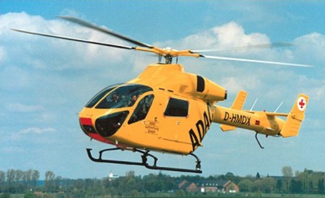
The genesis of the Explorer dates to 1986, when company engineers hit upon the idea of using the latest technology, such as an all-composite main rotor and MDHS’ own no-tail-rotor (NOTAR) anti-torque system, as a basis for a new eight-seater design which would give excellent performance at affordable cost. The MD Explorer is the first commercial helicopter totally designed using computer-aided design techniques and only after a detailed market survey of over 177 operators asking them what they wanted from a new utility helicopter in terms of flight performance and general layout in a 1800 to 3600kg helicopter.
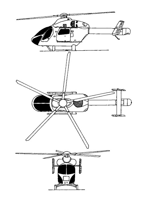
MDHS decided to go ahead with design work in January 1989 with a senior advisory council formed from risk-sharing partners in the $200 million programme. The Explorer is created using computer-aided design (CAD) techniques. The Explorer is the first helicopter to have a major portion of its primary structure constructed from composites. This is most evident in the fuselage, which is manufactured by Hawker de Havilland in Australia. Skins, floors, mb/keel beam and aft-fuselage assemblies are made from a pre-impregnated carbon-fibre composite with a toughened epoxy resin system produced by Hexel. Hawker de Havilland refined manufacturing techniques after the first three fuselage units and standardised on a final design which is around 10% lighter than the development fuselages, weighing in at just 260kg. Metallic parts consist of the titanium roof which provides protection from fire in the engine area, the main frames, fittings and forward-cockpit structure. Two aluminium plough beams form the primary structural support for the nose and provide enhanced crash-protection. In the event of a forward impact with the ground, the beams are designed to keep the nose of the helicopter from tipping down. In the passenger configuration, the Explorer’s 1.44m-wide cabin provides enough space for two rows of three 480mm seats , with a seventh passenger seated in the co-pilots position. Without seats, the helicopter has a completely flat floor which is accessible via a rear-access door and large sliding doors on either side of the cabin. The tailboom and empennage are all-composite primary structures made by MDHS using the same carbon composite and toughened resin as the fuselage. Like the fuselage, the early tailboom design was altered slightly for the final-production configuration to give a 25% weight saving. As the tailboom is hollow to accommodate the NOTAR system, it has aerodynamic surfaces on the inside, as well as the outside. Slots run the length of the right-hand side of the boom to allow air to escape and create the Coanda effect at the heart of the NOTAR principle.
Initially known as MDX, then MD 900 (proposed MD 901 with Turbomeca engines was not pursued. Hawker de Havilland of Australia designed and manufactures airframe; Canadian Marconi tested initial version of integrated instrumentation display system (IIDS) early 1992; Kawasaki completed 50 hour test of transmission early 1992. Other partners include Aim Aviation (interior), IAI (cowling and seats) and Lucas Aerospace (actuators).
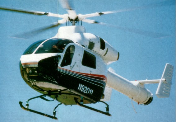
Ten prototypes and trials aircraft, of which seven (Nos. 1, 3-7 and 9) for static tests, were built. The first flight (No.2/N900MD) was on 18 December 1992 at Mesa, Arizona, followed by No.8/N900MH 17 September 1993 and No.10/N9208V 16 December 1993; first production/demonstrator Explorer (No.11/N92011) flown 3 August 1994.
FAA certification 2 December 1994; first delivery 16 December 1994; JAA certification July 1996; FAA certification for single-pilot IFR operation achieved January 1997. Type certificate transferred to MDHI on 18 February 1999.
This new technology helicopter received type certification on 21 December 1994 from the FAA which was only 23 months after first flight. This was one of the shortest certification periods ever recorded for a new helicopter and was also the first new design passenger and utility rotorcraft certified by the FAA in more than ten years.
FAA certification of uprated PW207E engine achieved in July 2000, providing 11% more power for take-off and 610m increase in hovering capability OEI in hot-and-high conditions; first delivery of PW207E-engined Explorer to Police Aviation Services, UK, 27 September 2000. “100th production” Explorer (actually 89th overall, including prototypes) delivered 1 March 2002 to Tomen Aerospace Corporation of Japan for ENG operations by Aero Asahi of Hiroshima. Total fleet time stood at more than 120,000 hours by December 2002.
MDHS begun delivery of the Explorer with a target direct-operating cost of $389/h and a base price of $3.16 million at 1995 exchange rates.
The Explorer has been built largely from composite materials and is powered by twin Pratt & Whitney Canada PW 206A turboshafts and has a maximum gross weight of 2950kg. It can lift 1150kg internally, or 1350kg externally and weighs only 1350kg empty. The helicopter incorporates a range of new technologies to improve safety and performance and reduce operating costs. These include the NOTAR yaw control system, composite, bearingless main rotor with five blades. Digital avionics including FADEC, diagnostics and an Integrated Instrument Display System. The liquid crystal Integrated Instrument Display System (IIDS) replaces traditional cockpit instruments by presenting aircraft operating information in a digital format and icon symbology on two six-inch screens. The system also records operating data for on-board health and usage monitoring, providing technicians with accurate information for performing maintenance functions.
The NOTAR anti-torque system features all-composites five-blade rotor of tapered thickness with parabolic swept outer tip with bearingless flexbeam retention and pitch case; tuned fixed rotor mast and mounting truss for vibration reduction; replaceable rotor tips; maximum rotor speed 392 rpm; modified A-frame construction from rotor mounting to landing skids protects passenger cabin; energy-absorbing seats absorb 20 g vertically and 16 g fore and aft; onboard health monitoring, exceedance recording and blade track/balance.
Mechanical engine control from collective pitch lever is back-up for electronic FADEC. Automatic stabilisation and autopilot available for IFR operation. The transmission overhaul life 5,000 hours; glass fibre blades have titanium leading-edge abrasion strip and are attached to bearingless hub by carbon fibre encased glass fibre flexbeams; rotor blades and hub on condition.
The baseline MD 900 is powered by two Pratt & Whitney Canada PW206E turboshafts with FADEC, each rated at 463kW for 5 minutes for T-O, 489kW for 2.5 minutes OEI and 410kW maximum continuous. Transmission rating 820kW for T-O, 746kW maximum continuous, 507kW for 2.5 minutes OEI and 462kW maximum continuous OEI.
Fuel contained in single tank under passenger cabin, capacity 564 litres, of which 553 litres are usable. Single-point refuelling; self-sealing fuel lines.
Accomodation is for two pilots or pilot/passenger in front on energy-absorbing adjustable crew seats with five-point shoulder harnesses/seat belts; six passengers in club-type energy-absorbing seating with three-point restraints; rear baggage compartment accessible through rear door; cabin can accept long loads reaching from flight deck to rear door; hinged, jettisonable door to cockpit on each side; sliding door to cabin on each side.
Hydraulic system, operating pressure 34.475 bar.
With 14 feet of flat floor space in the rear cabin, the Explorer is expected to undertake a multitude of civil missions from general utility to offshore transportation, corporate flight, tourist flights and air medical services. In the EMS configuration the Explorer can accommodate two patients, two attendants and life support equipment in addition to the flight crew.
The 100th Explorer registered in 2002 (to become seventh for Netherlands police); total of 108 manufactured by December 2002; first delivery 16 December 1994 to Petroleum Helicopters Inc (PHI) which ordered five; second delivery (N901CF) December 1994 to Rocky Mountain Helicopters for EMS duties with affiliate Care Flight unit of Regional Emergency Medical Services Authority (REMSA) in Reno, Nevada. Total of two delivered in 1994, 12 in 1995, 15 in 1996, one in 1997, four in 1998, 11 in 1999, 16 in 2000, 20 in 2001 and four in 2002; initial (MD 900) series comprised 40 aircraft including three flying prototypes; FW207E engine from 64th production (67th overall) aircraft.
MD Enhanced Explorer: Improved version, announced September 1996; originally MD 902, but now known as “902 Configuration”. Main features include Pratt & Whitney Canada PW206E engines with increased OEI ratings; transmission approved for dry running for 30 minutes at 50% power; improved engine air inlets, NOTAR inlet design and engine fire suppression system, and more powerful stabiliser control system, resulting in 7% increase in range. 4% increase in endurance and 113kg increase in payload over Explorer. First flight (N9224U; c/n 900-0051, 41st Explorer) 5 September 1997, FAA certification to Category A performance standards (including continued take-off with one failed engine) and single-pilot IFR operation achieved 11 February 1998; JAA certification for Category A performance achieved July 1998. Retrofit kits to convert Explorers to Category A standard. First Enhanced Explorer delivery in May 1998 to Tomen Aerospace of Japan. PW206E replaced by PW207E from late 2000, beginning at c/n 900-0077, allowing further MTOW increase to 2,948kg.
MH-90 Enforcer: Beginning March 1999, under a programme code-named Operation New Frontier, the US Coast Guard used two leased MD 900 Explorers for shipboard anti-drug smuggling operations. Armed with a pintle-mounted M240 7.62mm minigun at the door station. In September 1999 the MD900s were exchanged for two leased MD 902 Enhanced Explorers. These subsequently replaced by Agusta A 109s. Six delivered to Mexican Navy at Acapulco (two each respectively in May and December 1999 and April 2000) for anti-drug operations, equipped with 12.7mm General Dynamics GAU-19/A Gatling guns, and 70mm rocket pods; further four in process of delivery. Weapons qualification trials were completed at Fort Bliss, Texas in November 2000.
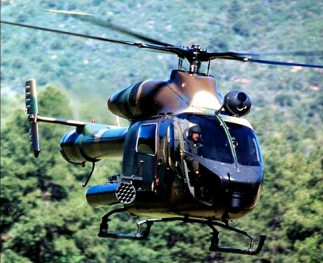
Combat Explorer: Displayed at Paris Air Show, June 1995; demonstrator N9015P (No.15), an MD 900 variant. Can be configured for utility, medevac or combat missions; armament and mission equipment may include seven- or 19-tube 70mm rocket pods, 12.7mm machine gun pods, chin-mounted FLIR night pilotage system and roof-mounted NightHawk surveillance and targeting systems. Combat weight 3,130kg; two P&WC PW206A engines. No customers announced by January 2000, but N9015P became one of initial two MH-90s (with third prototype, N9208V).
February 19, 1999: Boeing sold MD commercial line to RDM The dutch company bought the ex Mc Donnell Douglas models MD 500E and MD 530F single-engine helicopters with conventional tail rotors, the MD 520N and MD 600N single-engine NOTAR helicopters and the MD Explorer series of twin-engine, eight-place helicopters.
Costs: US$2.285 million (2002); direct operating cost US$408.11 (2002) per hour.
McDonnell Douglas MD 902 Explorer Engine: 2 x Pratt & Whitney Canada PW206E, 630 shp Length: 32.316 ft / 9.85 m Height: 12.008 ft / 3.66 m Rotor diameter: 33.825 ft / 10.31 m Wing area: 3939.624 sqft / 366.0 sq.m Max take off weight: 6504.8 lb / 2950.0 kg Weight empty: 3214.9 lb / 1458.0 kg Max. speed: 160 kts / 296 km/h Cruising speed: 140 kts / 259 km/h Initial climb rate: 2795.28 ft/min / 14.2 m/s Service ceiling: 18497 ft / / 5638 m Wing load: 1.64 lb/sq.ft / 8.0 kg/sq.m Range: 313 nm / 580 km Crew: 2 Payload: 8pax
MD Explorer Engine: 2 x Turbomeca Arrius 2C Instant pwr (Turbomeca engine): 480 kW. Rotor dia: 10.3 m MTOW: 2700 kg Useful load: 1165 kg Max cruise: 150 kts Max range: 600 km Seats: 8
MD Explorer Engine: 2 x P&WC PW206A Gross wt: 2,722kg Empty operating wt: 1,481kg Useful load: 1,163kg Fuel capacity wt (600litres): 438/472kg Main rotor dia: 10.34m Length: 9.86m Height: 3.66m Skid width: 2.23m Passengers: 7. Crew: 1 Max cruise speed @ ISA 38oC: 135kt (@sea level ISA: 139kt) Max range: 530km Max endurance: 3.5hr Hover Out of ground effect @ ISA: 3,353m (@lSA+20o: 2,073m) Hover in ground effect @ ISA 3901m (@lSA+20o: 2,621m) Climb rate: 14.2m/s Ceiling: 20,000ft
MD 900 Explorer Engines: 2 x Pratt & Whitney PW 206B turboshaft, 469kW Rotor diameter: 10.31m Length with rotors turning: 11.83m Fuselage length: 9.85m Height: 3.66m Fuselage width: 1.63m Max take-off weight: 3057kg Empty weight: 1481kg Max speed: 278km/h Cruising speed: 250km/h Rate of climb: 14.2m/s Hovering ceiling: 3840m Service ceiling: 6100m Range: 530-600km Payload: 1360kg Crew: 1-2 Passengers: 6
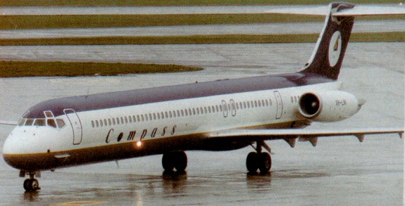
The advanced technical successor to both the DC 9 and MD 80, the MD 90, was launched in 1989 and entered passenger service with Delta Air Lines in April, 1995. Four and a half feet longer than the MD-88, it allowed for ten more passenger seats. Unlike any of its forebears the MD 90 is powered by International Aero Engines V2500 turbofans rated at 11.1 kN (2,500 lb) take off thrust and has a non stop range of 3,862km (2,082nm) with full payload.
The MD-90 made its first flight on 22 February 1993, three days ahead of schedule. The aircraft took off from the main runway at Long Beach Municipal Airport at 9.44am for a 4 hr 56 min flight.
During 1991, McDonnell Douglas received 27 MD-80/90 orders.
The MD 90 was selected in 1992 as the China Trunkliner for domestic and regional routes. In 1994, an amended co production agreement for 40 aircraft was signed by McDonnell Douglas and the China National Aero Technology Import and Export Corporation. This agreement called for the production of 20 MD 90s in Shanghai and the direct sale of 20 aircraft from Douglas Aircraft in Long Beach. With the merger of Boeing and McDonnell Douglas the co production agreement was cancelled.
Boeing announced that it will discontinue both the MD-80 and MD-90 series in January 2000. The MD series of aircraft evolved into what became the Boeing 717.
MD-90 Engines two 25,000- lb. International Aero V2525D5 turbofans Gross wt. 156,000 lb Empty wt. 88,000 lb Cruise speed 437 kts Range 2,085- 3,022 nm Seats 141-187
The MD-80 series of aircraft were a stretched improvement of the DC-9. The first version of the jet was literally a re-engined DC-9. McDonnell Douglas launched the MD 80 in October 1977, as an advanced, quieter and more fuel efficient successor to the DC 9. Three years later on October 5, 1980, it entered airline service. Like the venerable DC 9, the new aircraft was offered to the market in a choice of passenger configurations and operating ranges. It was designated MD 80 to reflect its ability to meet the needs of the 1980s and beyond.
The aircraft was offered in five versions the standard size MD 81, MD 82, MD 83 and MD 88, plus the smaller MD 87. A blend of new and mature technology, the MD 80s were the first aircraft in their class to meet the stringent US FAA Stage III noise regulations for new designs, operating costs were among the lowest in commercial aviation and fuel consumption per passenger was up to 30% lower than the commercial jets they replaced. Thus, the three ‘E’s design objectives environment, economy and energy were satisfied.
In 1983 Douglas abandoned the famed ‘DC’ and adopted ‘MD’ for its designations, the DC-9 family becoming the MD-80 series. It proved to be by far the most successful of all versions, combining high capacity with good operating economy and very competitive first cost.
Pratt & Whitney JT8D 200 series turbofans power the MD 80. The MD 81 is certified with 209 engines, but higher thrust 217A and 217C plants are available for aircraft operating from high altitude, high temperature airports. The smaller MD 87 uses the 217C or 219 for short field operations and extended range flights. The MD 80 retains many of its predecessor’s features. For example, the airframe is basically the same as that of the DC 9 except that the MD-80 incorporates greater use of composites and has increased fuselage length and wingspan. By the autumn of 1997 the combined total of DC-9s and MD 80s in airline service exceeded 2,000 aircraft.
The MD-80 entered service with Swissair on 5 October 1980, at a weight of 140,000lb. This soon became the MD-81, the baseline version for a growing family. The MD-82, announced in April 1979, introduced -217 engines of 20,000-lb thrust, giving better performance from difficult airports, and 25 have been assembled in China.
The MD-83 is a longer-range model, with 21,000-lb -219 engines making possible a weight of 160,000lb, mainly accounted for by two extra fuel tanks in the underfloor area in place of cargo.
The MD-87, announced in January 1985, is odd man out, with a shorter fuselage seating up to 130; it also introduces aerodynamic improvements and a taller vertical tail, one of its features, a rear knife -edge instead of a tailcone, now being standard on all models.
The MD-88 version, announced in January 1986, combines most of the new features and adds a modern cock¬pit and improved cabin.
During 1991, McDonnell Douglas received 27 MD-80/90 orders.
Boeing announced that it would discontinue both the MD-80 and MD-90 series in January 2000.
MD-80 Max wt: 140,000 lb Max speed: 498kts (925km/h)
MD-81 Engines 2 x 18,550-lb. s.t. Pratt & Whitney JT8D turbofans. Non stop range: 2,900km (1,560nm) Max speed: 498kts (925km/h) Seats 142-172 Gross wt. 140,000 lb Empty wt. 78,420 lb Fuel capacity 4,812 gal Max cruise 500 kts Long range cruise 440 kts Ceiling 35,000+ ft Range 1,563-2,630 nm Takeoff distance 7,250 ft Landing distance 4,860 ft
MD-82 Engine: 2 x Pratt & Whitney JT8D-217, 20,000 lb st Pax seats: 172 Crew: 2 Length: 45.06m Height: 9.04m Wingspan: 32.87m Max speed: 498kts (925km/h) Max range: 3798 km
MD-83 Engine: 2 x -219, 21,000 lb st Max wt: 160,000 lb Non stop range: 4,635km (2,498nm) Max speed: 498kts (925km/h)
MD-87 Pax seats: 130 Non stop range: 4,400km (2,372nm) Optional range: 5,250km (2,830nm) Max speed: 498kts (925km/h)
MD-88 Non stop range: 3,780km (2,037nm) Max speed: 498kts (925km/h)
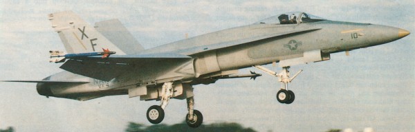
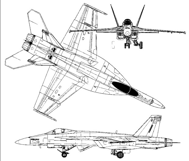
The McDonnell Douglas F/A-18 Hornet is a twin-engine carrier-based attack fighter derived from the YF-17 Cobra attempt at a new USAF lightweight fighter, on which the USN was a minor partner (the F-17 lost out to the YF-16).
The Navy preferred the YF-17 over the winning F-16 Fighting Falcon, because of its twin-engine design. For the Navy version, Northrop teamed with McDonnell Douglas and when the two services ended up choosing different aircraft, McDonnell Douglas became the primary contractor for the Navy design (McDonnell Douglas merged with Boeing in 1997).
The Navy’s design concept originated from Vice Admiral Kent Lee. An experienced naval aviator in WWII, he and his supporters pushed for a cheap and lightweight strike fighter, to complement the F-14 Tomcat which had become operational and was just being introduced to the carrier air wings in 1973.
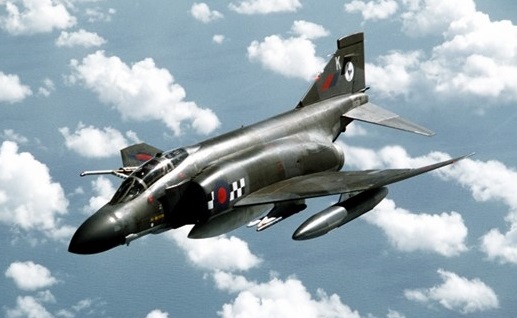
The F/A-18 has a digital fly-by-wire flight control system, the cockpit equipped with three multi function displays. The entire avionics suite is digital. The F-18 is powered by two 71 2kN General Electric F404 reheated turbofans, and equipment includes a Hughes APG-65 radar with air-to-air and air-to-surface modes giving intercept and attack capabilities, a Ferranti/Bendix headup display, Kaiser multifunction displays, and Litton INS. Other externally carried sensors include laser tracker and Flir pods. As a carrier-capable platform, the F/A-18 maintains folding wings. The Hornet is capable of air-to-air refuelling.
The first of 11 full-scale development (FSD) Hornets flew on November 18, 1978, and was followed by the first production aircraft in April 1980. F/A-18 Hornets (A and B variants) entered service in 1983, replacing the F-4 Phantom II and the A-7 Corsair II. F/A-18A/B were single and two seat aircraft. The F-18B two-seat trainer retains full operational capability with only a six per cent reduction in internal fuel capacity.
FY1986 and subsequent purchases are of the upgraded F-18C/D variants, which have AIM-120 Amraam and infrared Maverick compatibility, airborne self-protection jammers, Naces ejection seats, and improved computers. The first F-18C flight occurred in mid-1986. After a production run of 371 F/A-18As, manufacture shifted to the F/A-18C/D single and two seat variants in September 1987. Seventy-seven F-18A single-seaters and eight F-18B two-seaters delivered during 1986, including 24 for the USMC.
MDC handed over the 500th F-18 Hornet, an A model for the USMC, in May 1987.
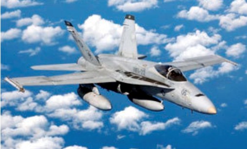
Although the single seat variants, A and C, were first equipped with the AN/APG-65 radar, since 1994 all US Hornets feature the improved AN/APG-73 radar. The second seat of the B and D models is often manned by a weapon system operator or instructor.
F/A-18
Test¬ing of a reconnaissance version, the US Navy F-18(R) continued. The nose-mounted 20mm rotary cannon was replaced by a sensor pallet with panoramic camera and infrared linscan. The aircraft can be reconfigured overnight for strike missions.
Licence-assembly of Hornets continued in Australia in 1987, where GAF has deliv¬ered more than 20 to the Royal Australian Air Force.
The CF-18 is the designation used for the Canadian licensed built aircraft. The Canadian Armed Forces purchased 138 examples of the CF-18 including 24 CF-18B two-seaters.
The first prototype F/A-18E Super Hornet flew on November 29, 1995.
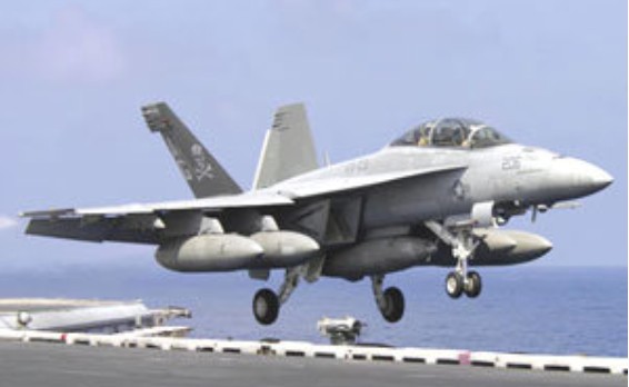
The F/A-18E/F “Super Hornet” arrived in 2002 and represented an aircraft that was 20 percent larger and more powerful than the base Hornets. The Super Hornet is produced by a consortium of contractors that includes Boeing and Northrop Grumman. The tandem-seat Super Hornet was designed to be ultra-capable in both strike and interceptor roles and squadrons are already operating on various USN carrier battle groups. The Super Hornet is built on the F414-GE-400 series of powerplants, which stands as a highly advanced modified version of the original F404 turbofans, bigger air intakes, and the airframe itself is longer. A 33% larger internal fuel capacity and larger ordnance carrying capacity improves the range significantly. As a whole, the Super Hornets, despite their advanced infrastructure, is compiled of less parts than the original Hornets making the Super Hornet that much easier to maintain. Additional hardpoints make the Super Hornet a viable replacement to the F-14 Tomcat and A-6 Intruders.
F/A-18E Super Hornet
The F/A-18E (single seat) and F/A-18F (two seat) Super Hornets provides increased range and improved combat mission endurance. The Super Hornet also makes use of an increased payload. F/A-18F Super Hornets with a WSO in the rear seat are replacing the F-14 Tomcat.
The US Navy took delivery of its first Super Hornet in 1999. Super Hornets are larger than the original models with many detail improvements. Their increased wing area allows them to carry more stores further on their extra hardpoints. They are most easily recognised by their rectangular engine air intakes.
The Royal Australian Air Force was to obtain 24 Boeing F/A-18F Super Hornets by 2010, until the full introduction into service of the F-35 Lightning Joint Strike Fighter. Twenty-four F/A-18F Super Hornets were to replace the F-111s at Nos 1 and 6 Squadrons at RAAF Base Amberley from 2010.
Boeing modified an F/A-18 Super Hornet as the EA-18 airborne electronic attack (concept) aircraft, carrying three ALQ-99 jamming pods.
The EF-18 designation is also used for Spanish F/A-18A/B Hornets (EF-18A and EF-18B) where the E stands for Espanga.
The RF-18 which is a dedicated reconnaissance version.
The Boeing EA-18G Growler electronic warfare variant, to replace the EA-6B Prowler, differs from the F/A-18F in several areas. It is wired in production differently with additional wiring and databuses from the wing stations and various fuselage antennae points. The nose gun is replaced with additional avionics for jamming missions, and carries two ALQ-218 tactical jamming receivers pods on the wingtips, and between one and five AN/ALQ-99 jammers on centreline and wing stations. There remains two wing and two should stations. It is also equipped with the APG-79 AESA radar.
The F/A-18 first saw combat action in 1986, when Hornets from the USS Coral Sea (CV-43) flew SEAD missions against Libyan air defenses during the attack on Benghazi.
Ten F/A-18’s were lost in the Gulf War, most to surface to air missiles although one was alleged to have been shot down by an Iraqi MiG-25PD in the first hours of the air campaign. F/A-18’s were credited with two kills, both of MiG-21’s, during that conflict.
Operators: US Navy, US Marine Corps, Australia, Canada, Finland, Kuwait, Malaysia, Spain, Switzerland.
F/A-18A Engine: 2 x General Electric F404-400 turbofan, 7258 kg / 16,000 lb Wingspan: 11.43m / 37 ft 6 in Length: 17.07 m / 56 ft 0 in Wing area: 37.2 sq.m Empty wt: 10,460 kg MTOW: 21,887 kg / 48,253 lb Fuel internal: 6140 lt Max speed: 1912 kph / 1188 mph / 1.8 Mach Initial ROC: 45,000 ft / min Ceiling: 15,240 m TO run: 425 m Ldg run: 850 m Range: 3706 km / 2303 sm Combat radius: 740+ km Armament: 1 x 20 mm / 570 rds Hard points: 7 + 2 wing tips Max external load: 17,000 lb / 7711 kg Air refuel: Yes
F/A-18A (from early 1992) Engine: 2 x General Electric F404-GE-402 turbofans, 78.73 kN (17,700 lb st) with afterburning. Length 17.07m (56 ft 0 in) Height 4.66m (15 ft 3 in) Wing span 11.43m (37ft 6 in) Take-off weight (clean) 10.455 kg (23,050 lb) Max Take-Off Weight 25.401 kg (56,000 lb) Max level speed at altitude Mach 1.8+ / 1.915+ km/h / 1,190+ mph) Combat ceiling about 15,240m (50,000 ft) Armament: one 20mm M61A1 Vulcan six-barrel cannon with 570 rounds Disposable stores: 7031 kg (15,500 lb) Hardpoints 9
F/A-18B Engines: 2 x General Electric F404-GE-400 turbofan, 16,000lb / 7,258kg thrust Length: 17.1 m Wingspan: 12.4 m Height: 4.7 m Empty Weight: 23,049lbs (10,455kg) Maximum Take-Off Weight: 55,997lbs (25,400kg) Maximum Speed: Mach 1.8 / 2200 kph Maximum Range: 2,073miles (3,336km) Combat radius: 740km Rate-of-Climb: 45,000ft/min (13,716m/min) Service Ceiling: 50,033ft (15,250m; 9.5miles) Armament: 1 x M61 20mm cannon Hardpoints: 9 (including wingtip mounts) Seats: 2
F/A-18C
F/A-18D Seats: 2
F/A-18E Engines: 2 x General Electric F414-GE-400, 10000kg / 72.5kN Max take-off weight: 29937 kg / 66000 lb Empty weight: 13387 kg / 29513 lb Wingspan: 11.43 m / 37 ft 6 in Length: 18.31 m / 60 ft 1 in Height: 4.88 m / 16 ft 0 in Wing area: 46.45 sq.m / 499.98 sq ft Max take-off weight: 20000 kg / 44093 lb Max. speed: 1.8M Ceiling: 15240 m / 50000 ft Range: 1500 km / 932 miles Crew: 1
F/A-18F Super Hornet Engines: 2 x General Electric F414-GE-400 turbofan, 9,800kg. 22,000lbs thrust with afterburner. Length: 60.07ft (18.31m) Width: 44.69ft (13.62m) Height: 16.01ft (4.88m) Wing area: 46.45 sq.m / 499.98 sq ft Empty Weight: 30,565lbs (13,864kg) Maximum Take-Off Weight: 47,003lbs (21,320kg) Maximum Speed: Mach 1.6 / 1,960 kph Ferrying range: 2,700km Combat radius 740km Service Ceiling: 49,213ft (15,000m; 9.3miles) Armament: 1 x M61 20mm cannon Hardpoints: 11 Ordnance: 17,750 lb Crew: 2
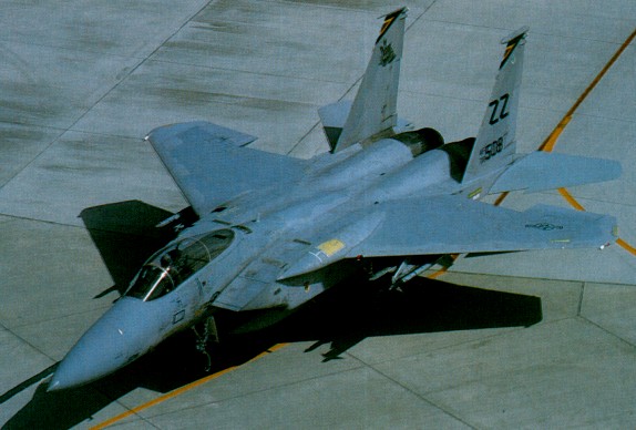
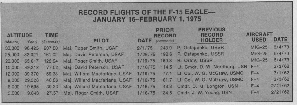
In September 1968, the USAF issued a request for proposals for a new FX fighter. The Air Force wanted a single air superiority fighter able to defeat the Mach 3 MiG 25 Foxbat, the MiG 21 Fishbed, and the MiG 23 Flogger. McDonnell was short listed and in late 1969 was selected to develop and produce the F-15 under the direction of Air Force Systems Command, full scale development being authorised in January 1970.
In February 1970, the Pratt & Whitney F100 turbofan was selected for development and a few months later the Hughes APG-63 radar was chosen for the F-15.
The initial contract called for 18 single-seat F-15As and two TF-15 trainers (re-designated F-15B in December 1977). The first F-15A was rolled out in June 1972, and made its maiden flight on 27 July 1972, to be joined by the first two-seater on 7 July 1973. Most of the major test hurdles had been successfully negotiated by late 1974, clearing the way for the Eagle to join TAC’s inventory.
The F-15 was the first USAF fighter to be developed under the DoD “Fly-Before-Buy” concept, but funding for long-lead items for the first wing of aircraft was released late in 1972, followed by full production funding in early 1973. The second wing was ordered late 1974. The first production aircraft was flown on 25 September 1974.
On 14 November 1974 President Gerald Ford formally accepted the first aircraft (actually a two-seat TF-15A designated F-15B) to be handed over to TAC at Luke AFB, Arizona. Initial operational capability was declared in July 1975, with delivery of the 24th aircraft, and the first wing was completely equipped by the end of 1976. From the outset the USAF planned a force of 729 production aircraft, of which 589 had been delivered by 1 May 1981.
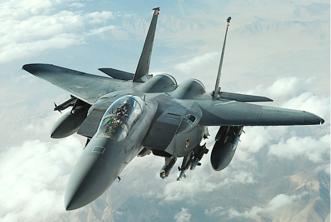
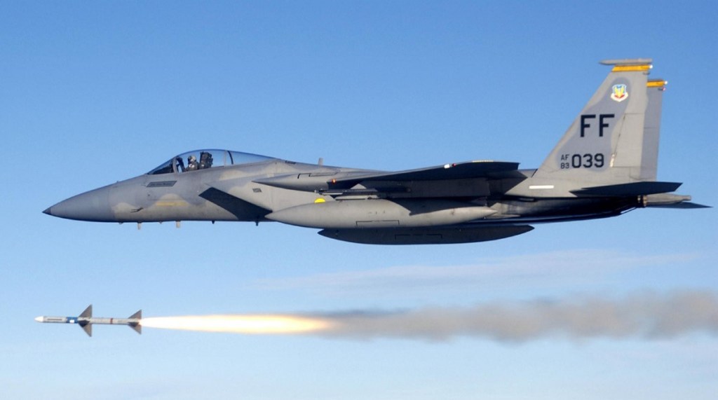
The first two models to enter service were the F-15A single-seater and TF-15A (later F-15B) combat-capable tandem two-seater. Both variants had the APG-63 radar and 10855kg Pratt & Whitney F100-P-100 afterburning turbofans, with AIM-7 Sparrow air-to-air missiles along the bottom of its large inlet ducts and 20mm cannon mounted in the right inboard wing. The two-seat F-15B combat trainer which first flew on 7 July 1973 is about 360kg heavier than the F-15A fighter, but retains most of its combat capability. The Eagle is equipped with Hughes APG-63 pulse-Doppler radar with computerised data-processing and the F-15 pioneered the HOTAS (hands on throttle and stick) concept.
The 1st Tactical Fighter Wing at Langley AFB, Virginia, was the first USAF recipient of the F-15A, while the first operational aircraft in Europe were assigned to the 36th TFW at Bitburg AB, West Germany.
The production totalled 366 and 58 respectively for the US Air Force plus 19 and two respectively for the Israeli Air Force.
Israel, the first export country, ordered 40 F-15 under the ‘Peace Fox’ program. Delivery started in 1976 on an initial batch of 25 aircraft. At least one Syrian MiG-23 has been shot down in clashes with Israeli F-15s over Lebanon.
Japan’s programme to acquire the F-15 began in 1975. The first of the two single-seat F-15Js produced by the parent company was accepted on 29 July 1980, with the second following on 29 July, and after 39 test flights with ASDF pilots, were ferried to Japan landing at Kadena Air Base on 1 March 1981. Essentially similar to the USAF’s F-15C, the F-15J differs in having various avionics changes, the Tactical Electronic Warfare System – the TEWS pod being omitted from the tip of the port fin.
Continuing procurement of the F-15A variant enabled two more TAG wings and one more USAFE squadron to be equipped between 1977-9, production thereafter switching to the F-15C and the basically similar two-seat F-15D.
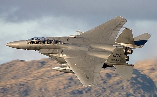
In June 1979 deliveries of the improved and more advanced F-15C single-seat (flown for the first time on 27 February 1979) and F-15D two-seat models began. Equipped with AGP-70 radar (with a programmable digital signal processor, synthetic-aperture ground mapping and track-while-scan air-to-air capability), an uprated powerplant, and provision for low-drag conformal packs carrying fuel and fitted with tangential attachments for weapons. The two variant were built for the USAF, Israel and Saudi Arabia and are still operated today. These variants were also built under licence in Japan by Mitsubishi and designated F-15J.
F-15D
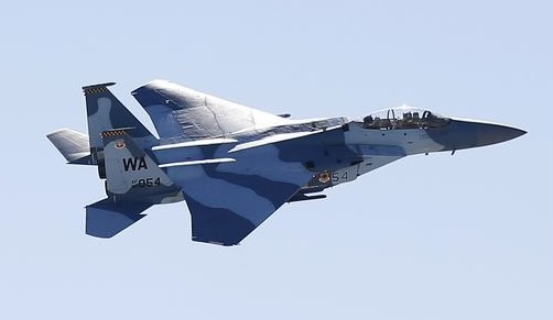
In addition, it is also compatible with the company-developed FAST (Fuel And Sensor Tactical) packs, whereby conformal fuel tanks and/or sensor packages can be attached to the outside of each air inlet. Extra fuel tanks conform to the sides of the fuselage and hold an additional 10,000 lb / 4536 kg of fuel to supplement the 11,600 lb / 5260 kg of internal fuel, or a variety of sensors (such as reconnaissance cameras, infra-red equipment, radar warning receivers, laser designators and low-light-level television cameras to be carried. Thus, overall capability the Eagle has been significantly enhanced. Operational deployment of the F-15C and F-15D began in 1979. The 18th TFW at Yridena, Okinawa, was the first unit to receive this version, re-equipment of this Wing’s three squadrons being effected between September 1979 and April 1980. Subsequent deliveries were made to existing Eagle units, most of which were progressively re-equipped during the early 1980s.
The first single-seat air superiority F-15C incorporating MSIP enhancements was rolled out in June 1985.
Renowned as an extremely capable interceptor, the F-15D Eagle was modified in 1980 to perform in the all-weather interdictor role whilst still retaining the ability to operate as an air superiority aircraft. This private venture, first known as the Strike Eagle, first flown on 8 July 1980, was redesignated McDonnell Douglas F-15E Enhanced Eagle when the USAF expressed interest in the concept and conducted an evaluation between November 1982 and April 1983. Together with the delta-winged General Dynamics F-16E, the Enhanced Eagle was competing for selection in the USAF’s Derivative Fighter Program as a supplement and eventual replacement for the General Dynamics F-111.
The dual-role F-15E Strike Eagle is basically a converted F-15B/D trainer for the ground-attack role. It has a total of 18 external hardpoints.
On 11 December 1986 the F-15E made its first flight and the US Air Force announced that it was to order 392 examples though this requirement was later reduced to 200 and deliveries began in 1988, initially to the 405th TTW for training and then the 4th TFW for operations, replacing the F-4E. The rear cockpit of the prototype (a converted F-15B trainer) has been fitted with four multi-purpose cathode ray tubes (CRTs) for information display to the systems operator and three more CRTs are to be installed for the pilot in production versions. Beneath the nose-cone, high resolution radar provides long-range ground-mapping of remarkable clarity, whilst forward looking infra-red (FLIR) gives close range images of similar quality. In combination, these systems allow rapid target identification in all weathers and ensure accurate weapon delivery. Ordnance carriage has been improved by addition of bomb attachment points on the ‘conformal’ wing-root fuel and sensor packs, resulting in less drag and freeing wing pylons for additional fuel tanks. Called Tangential Carriage, the modification extends the Eagle’s endurance by 40 per cent in some cases. During proving trials, the F-15E demonstrated an ability to take off at a weight of 34020 kg (75,0001b), some 3175kg (7,0001b) above the previous maximum.
McDonnell Douglas F-15E Strike Eagle
The type has an advanced nav/attack system with APG-70 main radar as well as several radar and infra-red navigation and targeting options displayed to the rear seat, leaving the pilot free to concentrate on tactical flying using his head-up display. Equipment installed in the F-15E includes the LANTIRN night nay/attack pod system, FLIR sensors, threat-warning displays, digital map displays, APG-70 radar, a wide-angle HUD an improved mission computer and provision for AIM-120 AMRAAM missiles and the integral M61 Vulcan cannon.
F-15E Strike Eagle
21 Strike Eagles were exported to Israel designated F-15I. The Israeli Defence Force/Air Force aircraft have been involved in several dogfights with Syrian MiG-21s and MiG-23s and are officially confirmed as having shot down at least one MiG-25. On 7 June 1981, Israeli F-15s escorted F-16s making the strike against Iraq’s Osirak nuclear powerplant, covering a radius of 966km.
On the 1st of November 1968, Japan signed a letter of agreement with Mc Donnell Douglas and it was also announced that it would become one of the few countries worldwide that was going to license-produce this aircraft. Over the following years, the Nihon Koku Jietai (Japan Air Self-Defence Force) received a total of 154 F-4EJ and RF-4Es. The F-4EJs (the export version for Japan) were mostly similar to the F-4Es, although the Japanese aircraft had their in-flight refuelling and ground-attack capabilities removed to align with Japan’s defensive posture, the F-4EJs were delivered without the AN/AJB-7 bombing computer system.
The first two F-4EJs (JASDF serials 17-8301 and 17-8302) were built by McDonnell Douglas in St Louis and first flew on January 14, 1971. The next 11 F-4EJs (JASDF serials 27-8303/8307, 37-8307/8310, and 47-8311/8313) were built by McDonnell Douglas in kit form and were assembled in Japan by Mitsubishi Heavy Industries, Ltd. The first Japanese-assembled aircraft (27-8303) flew on May 12, 1972. Seven more F-15Js single-seat version based on F-15C were to be assembled by August 1982, leading to manufacture by Mitsubishi against contracts placed for a total of 45 F-15Js and 12 two-seat F-15DJs (including two aircraft assembled in the USA by McDonnell Douglas). Funding of 43 more F-15Js in the FY82 budget brought total procurements to 100. Subsequently, Mitsubishi built all the rest 127 F-4EJ during the following nine years. The last example was delivered to the JASDF on May 20, 1981.
Mitsibishi produced 213 McDonnell Douglas F- 15J/DJ fighters for the JASDF by 1998.
Japan also acquired 14 RF-4Es built by McDonnell Douglas to serve in the reconnaissance role. These RF-4Es were delivered between November 1974 and June 1975. They were virtually identical to the USAF RF-4C, with the only differences being the deletion of certain equipment such as the radar homing and the warning suite which had not been released for export to Japan.
The F-4EJs entered service with the JASDF in August 1972 with a total of six squadrons operating the aircraft: the 301st, 302nd, 303rd, 304th, 305th and 306th squadrons. The RF-4Es equipped the 501st that had previously operated one of the less-well-known Sabre models, the RF-86F.
Korea ordered the Boeing F-15K to replace its F-4 Phantom II fleet. The F-15K is more advanced than the original F-15E, it has better radar and improved systems and a helmet-mounted cueing system.
Saudi Arabia ordered the F-15 variant and took delivery of 72 downgraded F-15Es, redesignated F-15S.
The F-15 Eagle has a perfect combat record of 101 victories and zero defeats. F-15s downed four Mig-29 fighters during the Balkan conflict and 33 of the 35 fixed-wing aircraft Iraq lost in air combat during Operation Desert Storm.
Singapore ordered the F-15SG (previously known as F-15T), another customized advanced derivative of the F-15E Strike Eagle, to replace the A-4 Skyhawk in the ground-attack role.
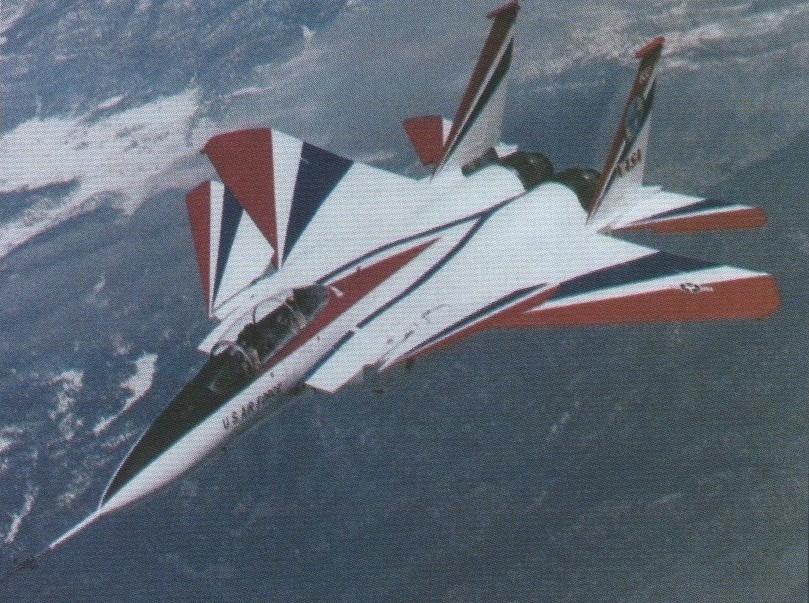
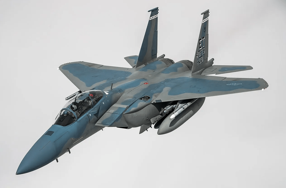
The McDonnell Douglas F-15S/MTD, AF71290, is the prototype F-15B modified under a $US117.8 million programme for the US Air Force Wright Aeronautical Laboratories to investigate short take-off and landing using vectored thrust jet nozzles and canards mounted on the engine intakes. The aircraft’s first flight was made on 7 September 1988 and after the fitment of the thrust vectoring reversing nozzles on the jet pipes these were flown for the first time on 10 May 1989. The aircraft was involved in a 13 month, 100 flight test schedule at Edwards. The aircraft’s controllable canard foreplanes are adapted tailplanes from the F/A-18 Hornet and can operate independently of each other for pitch and roll manoeuvres having a 20 degree dihedral.
The US signed a US$29.4 billion deal to sell 84 new F-15 fighter jets to Saudi Arabia in December 2011. The sale includes the 84 advanced Boeing F-15SA fighters with Raytheon Co radar equipment and digital. electronic warfare systems. Also included are upgrades that wilI bring Saudi Arabia’s 70 older F-15s up to the new standard, as well as HARM, AGM-88 AntiRadiation Missfies; Laser JDAM and Enhanced Paveway munitions and related equipment and services. The first new F-15s’ were expected to be delivered to Saudi, Arabia in early 2015.
By 1990, since the development two-seat Strike Eagle was displayed in 1984, this all-weather interdictor/strike aircraft has entered service with the USAF’s 4th TFW and production of 200 was underway. Powered by 23,800 lb st (10 800 kgp) P& W F100-PW-220s, the F-15E The F-15E has a range of 2,400 nm (4,445 km).
The Boeing F-15EX Eagle II represents the ultimate evolution of the F-15, thoroughly modernised to remain relevant against emerging threats.
The F-15EX incorporates 21st-century technology, including an APG-82 AESA radar, advanced cockpit displays, digital fly-by-wire controls, and the Eagle Passive Active Warning Survivability System (EPAWSS), a sophisticated electronic warfare suite that drastically improves survivability against modern air defence systems.
Powered by twin Pratt & Whitney F100-PW-229 engines, each producing 29,000 pounds of thrust, the F-15EX reaches Mach 2.5 (approximately 3,100 km/h).
It can carry up to 22 air-to-air missiles or a mix of air-to-ground ordnance. The US Air Force planned to acquire 144 F-15EX aircraft at $87 million each to replace aging F-15C/D models.
F-15EX_Eagle_II
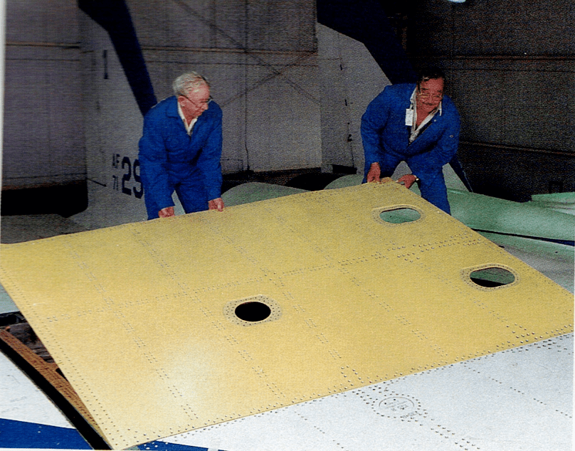
F-15 wing skin panel of aluminium-lithium alloy – lighter than conventional aluminium alloys
F-15A Engines: 2 x Pratt & Whitney F-100-PW-100, 29,000 lb. Wing span: 42 ft 9.75 in (13.05 m) Length: 63 ft 9.75 in (19.45m) Height: 18 ft 7.25 in (5.67m). Wing area: 56.5 sq.m / 608.16 sq ft Take-off weight: 18145-25000 kg / 40003 – 55116 lb Empty weight: 12245 kg / 26996 lb Max. speed: 2655 km/h / 1650 mph Ceiling: 20400 m / 66950 ft Range w/max.fuel: 8000 km / 4971 miles Range w/max.payload: 4500 km / 2796 miles Seats: 1 Internal fuel: 5278 kg (11,635 lb) Armament: 1 x 20mm Vulcan, 6800kg ordnance
F-I5B / TF-15A Engines: 2 x Pratt & Whitney, 29,000 lb. Wing span: 42 ft 9.75 in (13.05 m) Length: 63 ft 9.75 in (19.45m) Height: 18 ft 7.25 in (5.67m). Seats: 2 Weight: F-15A + approximately 363 kg (800 lb)
F-l5C Engine: 2 x P&W F100-220, 105.73 kN (23,770 lb st) Installed thrust (dry/reheat): 134 / 211 kN Span: 13.05 m (42ft 9.75in) Length: 19.43 m (63 ft 9in) Height: 5.63m (18ft 5.5in) Wing area: 56.48 sq.m (608 sq.ft) Wheel base: 5.42m (17ft 9.5in) Wheel tract: 2.75m (9ft .025in) Empty wt: 12,247 kg (27,000 lb) Take-off weight (clean): 20,244 kg (44,630 lb) MTOW: 30,845 kg (68,000 lb) Internal fuel: 6,103 kg (13,455 lb) Conformal fuel tank capacity: 4536 kg (10,000 lb) Max speed: 2.5+ Mach Time to height: 1 min / 12,200 m Service ceiling: 18,300 m TO run: 274 m Ldg run: 840 m Fuel internal (external): 6100 kg (9820 kg) Air refuel: Yes Combat radius: 1062 nm. Seats: 1 Hardpoints: 9 Armament: one 20mm M61A1 Vulcan six-barrel cannon with 940 rounds; 10,705 kg (23,600 lb) disposable stores
F-15D MTOW: 68,000 lb Fuel internal: 6100 kg Fuel external: 9820 kg Seats: 2
F-15E Powerplant: two 10855-kg (23,930-lb) thrust Pratt & Whitney F100-PW-100 afterburning turbofans. Span 13,05 m (42 ft 9¾ in) Length 19.43 m (63 ft 9 in) Height 5.63 m (18 ft 5½ in) Wing area 56.5 sq.m (608 sq ft). Maximum speed Mach 2.5 + at altitude Maximum speed 1481 km/h (920 mph) at sea level Ceiling 20000 m (65,610 ft) Endurance 5 hours 15 min Armament: one M61A1 Vulcan 20-mm gun (with 940 rounds) External load: 24,000 lb / 10,885 kg Hardpoints: 3 fuselage / 6 fuel pack Seats: 2
F-15E Eagle Engines: two 23,450-lb (10,637-kg) reheated thrust Pratt & Whitney F100-P-220 turbofans. Maximum speed 1,650+ mph (2,655+ km/h) or Mach 2.5+ at 36,000 ft (10,975 m) Climb to 39,370 ft (12,000 m): 1 minute 0 seconds Service ceiling 60,000 ft (18,290 m) Radius 1,150+ miles (1,851+ km) Empty weight 31,700 lb (14,379 kg) Maximum take-off 81,000 lb (36,742 kg) Wing span 42 ft 9.75 in (13.05 m) Length 63 ft 9 in (19.43 m) Height 18 ft 5.5 in (5.63 m) Wing area 608.0 sq ft (56.48 sq.m) Armament: one 20-mm multi-barrel cannon, up to 24,250 lb (11,000 kg) disposable stores.
F-15E Powerplant: two 129.45 kN (29,100 lb st) Pratt & Whitney F100-PW-229 turbofans Length 19.43m (63 ft 9 in) Height 5.63m (18 ft 6 in) Wing span (over tip launchers) 13.05m (42ft 10 in) Take-off weight (‘clean’) 14.515 kg (32,000 lb) Max Take-Off Weight 36.741 kg (81,000 lb) Wing loading: 133.25 lb/sq.ft / 650.0 kg/sq.m Max level speed at high altitude (‘clean’) 2,655+ km/h (1,650+ mph) Service ceiling: 60039 ft / 18300 m Max rate of climb at sea level 15,240+ m (50,000+ ft)/min Range int. fuel: 686 nm / 1270 km Max range 4,455 km (2,762 miles) Armament: one 20mm M61A1 Vulcan six-barrel cannon with 512 rounds; 11.000 kg (24,250 lb) ordnance Hardpoints: 18 Crew: 2
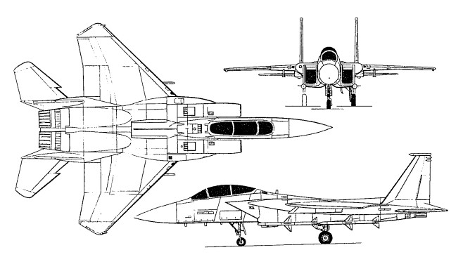
The low wings are swept back at 45 degrees, swept-back tail surfaces and 23 degrees anhedral on the one-piece all-moving tailplane. The wings have a ‘dog-tooth’ leading edge and dihedral on the outer panels which fold upwards for stowage. The ailerons move only down and are supplemented by spoilers on the upper surface of each wing. Trailing-edge flaps and small leading-edge flaps are blown. The tricycle undercarriage has a single wheel on each main unit and twin wheels on the nose unit. The mains retract inward into the wings and the nose wheels retract rearwards. A fire-control radar is in the nose, with infra-red equipment in a small bulge underneath.
The first flight for the F4H-1 Phantom prototype came on 27 May 1958. This aircraft differed from the 1955 mock-up mainly in the flying surfaces and around the jet intakes.
To protect against suspected lateral instability, the outer panels of the wings were canted upwards and the anhedral already planned for the tailplanes was increased. The jet intakes were enlarged and the edges cut back from the top to bottom.
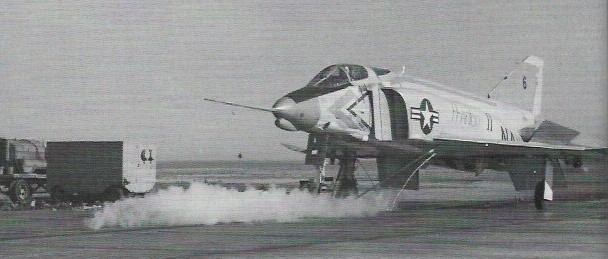
The sixth Phantom protype (BuNo 143391) was used for initial catapult launching testing.
sixth Phantom prototype (BuNo 143391) Feb 1960
By February 1960 a second missile had been added with an IR sensor, and an AAA-4 seeker was fitted under the radome of the F4H-1’s 24in antenna APQ-50 search radar.
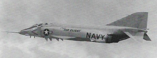
In late 1959, after it had been relieved of primary test responsibilities by the four remaining RTD&E airframes, the first Phantom far assigned to Project ‘Top Flight’, for a manned aircraft altitude record. On 6 December 1959 it reached 98,557 ft, breaking the previous Russian record by more than 4000ft.
Operation Top Flight
Powered by two 7711kg afterburning thrust General Electric J79-GE-8 engines. The first Phantom attained a speed record of 2585km/h on 22 November 1961, and a low-altitude speed record of 1452km/h on 20 August 1962.
During the testing of early Phantoms, some problems had been encountered with the original design of the intake, and in an attempt to improve airflow at all speeds a number of different configurations were tried. Here the splitter plate has been enlarged and the rake in the leading edge eliminated.
Of the 47 F4H-1/F-4As, 27 were assigned to test duties, the remainder going to training squadrons.
Eleventh Phantom BuNo 145310 with another variation in splitter plate and intake leading-edge design, and extended cooling intake behind radome which replaced NACA-style flush inlet of earlier prototypes.
The first squadron to receive F4H-1s was the ‘Grim Reapers’ of VF-101. The eleventh prototype was re-assigned from RTD&E to Det A of VF-101 in 1961.
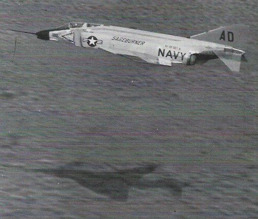
Aircraft 145310 in August 1951 was in Operation Sageburner, a high-speed, low altitude, cross-country test run from San Diego, California, to NAS Oceana, Virginia.
Operation Sageburner
Aircraft 145310 was again on test duties in June 1963, by now designated F-4A.
Aircraft 145310 June 1963
The F-4B differed from the -A with a larger radar, the 32in-diameter APQ-72 introduced on a few F-4As, became standard, along with the requisite larger radome; the back seat was raised; and the entire canopy redesign was altered to give better forward vision for both crewmen. F-4Bs were also fitted with uprated engines, J79-GE-8s, in place of the -A’s -2s.
F-4B BuNo 149449
F-4B BuNo 149449 was assigned Project ‘High Jump’ to break the world’s time-to-climb records. During April 1962 new records were set at all eight recognised height increments between 3000 and 30,000m, reaching 30,000m in 371.43 seconds.
Production of the F 4B amounted to 649 aircraft. A large number of the F 4Bs have since been updated to F 4N standard
The RF-4B reconnaissance derivative served only with the US Marine Corps. The RF-4B was the second photo reconnaissance version of the Phantom, being a standard F-4B fitted with the nose developed for the Air Force F-4C. The first was RF-4B BuNo 151975t.
RF-4B BuNo 151975t March 1965
Photo Phantoms exchanged the large APQ-72 for a smaller APQ-99 radar.
The USAF reached an agreement with the Navy to take 27 more F-4Bs off the assembly line, all to be re-designated F-4C. A series of changes to the basic F-4B were implemented to make the Phantom more suitable for land-based service. These included larger, low-pressure mainwheel tyres (necessitating the thickening of the wing root) and the fitting of full dual controls and cartridge starters. The Navy retractable refuelling probe was replaced by a receptacle behind the cockpit.
The fourth F-4C 63-7410 on 27 Jan 64
The F-4C (F-110A) Phantom was the initial version for the USAF. The USAF’s Phantom II program was first designated F-110A Spectre but this name was later dropped and the USAF’s Phantom II was designated F-4C. The USAF F-4C made its first flight on May 27, 1963, and production deliveries began in November 1963 and the F-4C became operational with the 12th and 15th Tactical Fighter Wings at MacDill AFB, Florida, in January 1964. The F 4C was powered by J79 GE 15 engines.
Although very similar to the US Navy’s F-4B, it included some slight differences to make the aircraft suitable for air force use. Some of the items are: 1. The probe-and-drogue method of in-flight refuelling favoured by the US Navy was discarded in favour of the standard USAF boom’ method. 2. Full flying controls and instrumentation were duplicated in the rear cockpit. 3. In order to allow use from un-sophisticated airfields an anti-skid braking system was fitted, which included the use of thicker main-wheels. 4. The USAF version could carry a greater variety of external wea¬ponry.
The aircraft has flown a lot of combat mission in South-East Asia during the Vietnam War and has claimed 277 air-to-air combat victories.
During the Vietnam War in 1967 production was 72 Phantom IIs a month. 583 F 4Cs were built. 40 were transferred to Spain.
The service-test YRF-4C (YRF-110A) led to the RF-4C (RF-110A), 499 of which were constructed for the photo-reconnaissance role. Consideration was given to the possibility of developing a reconnaissance configured variant of the McDonnell Douglas F-4 Phantom at an early stage in the type’s operational career, but it was not until the US Air Force selected, the basic fighter model to equip Tactical Air Command units that this proposal began to move ahead rapidly. Known by the designation RF-4C, the resulting aircraft flew in prototype form for the first time on 8 August 1963, the last of which was formally handed over to the USAF over 10 years later, on 16 January 1974.
Easily recognised by the modified nose section which contains cameras and other reconnaissance sensors, the RF-4C entered operational service at Shaw AFB, South Carolina, in September 1964, although nearly a year passed before the first unit could be considered as combat ready. When that milestone was reached, overseas deployment followed quickly, aircraft being dispatched to South East Asia for combat duty by the end of 1965, and the RF-4C remaining in use as the principal tactical reconnaissance tool for the remainder of the Vietnam War.
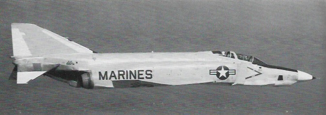
The second reconnaissance model to appear, designated RF-4B, was intended specifically for service with the US Marine Corps and this made its maiden flight on 12 March 1965 with deliveries to El Toro, California, following just two months later. A total of 46 RF-4Bs was supplied to this service, and were the subject of modification and life-extension programmes.
By the mid-1960s, the Phantom was just about the best-known fighter in the world. On 2 January 1967 in Operation ‘Bolo’, F-4Cs of the 8th TFW under Colonel Robin Olds shot down seven North Vietnamese MiGs. Increasingly, F-4Ds took over from the Republic F-105 the job of bringing ordnance to bear on Vietnamese ground targets.
F-4 Phantom IIs in Israeli service are claimed to have shot down 116 aircraft during a number of conflicts.
Some F 4Cs were converted into EF 4Cs under the ‘Wild Weasel’ programme to suppress enemy weapon radar systems.
The F-4D differed from the -4C externally only in having a slightly larger nose cross-section, in order to house the new APQ-109 radar with its improved air-to-ground capability. A new weapons release computer and 30kVA generator occupied the forward fuselage fuel cell, reducing fuel capacity and range.
The F-4D Phantom fighter-bomber introduced a capability to deliver precision-guided munitions (PGM), or ‘smart’ bombs. Some 825 were built, including 32 delivered new to Iran and 36 transferred to South Korea.
On 28 March 1974, the Royal Hellenic Air Force received the first of 38 F-4 Phantom IIs ordered.
Once in action in Vietnam in 1965, the Phantom seemed to need a gun to augment its missile armament in close-quarter battles with MiGs. The SUU-16/A 20mm external gun pod was an interim measure. The F-4E, first flown on 7 August 1965, introduced the 17,900 lb thrust (with afterburning) General Electric J79-GE-17 engines but its principal change was the internally-mounted M61A1 20mm cannon. The F-4E established a 2.5-to-1 kill advantage over North Vietnamese MiG-17, MiG-19 and MiG-21 fighters. Armament is one 20 mm M61A 1 multi barrel cannon and eight air to air missiles or up to 16,000 lb (7,250 kg) of ground attack weapons.
The F-4E became the definitive Phantom, and 1,397 rolled off the line. Examples were supplied to Australia (on loan), Greece, Iran, Israel, Turkey, South Korea and West Germany. The RF-4E was an export reconnaissance derivative, supplied to Greece, Iran, Israel, Japan and West Germany.
As well as producing reconnaissance Phantoms for the home market, McDonnell Douglas also developed the RF-4E variant, initially in response to a Luftwaffe requirement for 88 aircraft to undertake this mission. Flown for the first time on 15 September 1970, the RF-4E subsequently also joined the air arms of Greece, Iran, Israel, Japan and Turkey, just over 160 aircraft of this type being built before production ceased.
The RF 4E reconnaissance version and the F 4M RAF version carrys the service designation FGR.Mk 2.
The F-4F was a specialised air superiority version for the West German Luftwaffe, and 175 were delivered. The F-4G designation had been used initially for 12 aircraft taken from the US Navy F-4B production line. They had the two-way ASW-21 data-link system for automated carrier landings, and all later reverted to F-4B standard. In the 1970s, the F-4G appellation was used again for the US Air Force’s ‘Advanced Wild Weasel’ electronic warfare aircraft, 116 of which were converted from F-4E standard. Originally seen as a counter to enemy SAM missile sites and associated radars, the F-4G now carries out a wide portfolio of electronic missions. Aircraft are stationed as far afield as the 3rd TFW Clark Field, Philippines, and 52nd TFW, Spangdahlem AB, West Germany.
The F-4J was an improved production fighter for the US Navy with 8119kg afterburning thrust J79-GE-10 engines, enlarged wing and improved avionics.
On the 1st of November 1968, Japan signed a letter of agreement with Mc Donnell Douglas and it was also announced that it would become one of the few countries worldwide that was going to license-produce this aircraft. Over the following years, the Nihon Koku Jietai (Japan Air Self-Defence Force) received a total of 154 F-4EJ and RF-4Es. The F-4EJs (the export version for Japan) were mostly similar to the F-4Es, although the Japanese aircraft had their in-flight refuelling and ground-attack capabilities removed to align with Japan’s defensive posture, the F-4EJs were delivered without the AN/AJB-7 bombing computer system.
The first two F-4EJs (JASDF serials 17-8301 and 17-8302) were built by McDonnell Douglas in St Louis and first flew on January 14, 1971. The next 11 F-4EJs (JASDF serials 27-8303/8307, 37-8307/8310, and 47-8311/8313) were built by McDonnell Douglas in kit form and were assembled in Japan by Mitsubishi Heavy Industries, Ltd. The first Japanese-assembled aircraft (27-8303) flew on May 12, 1972. Subsequently, Mitsubishi built all the rest 127 F-4EJ during the following nine years. The last example was delivered to the JASDF on May 20, 1981. This was the last F-4 ever built in the world.
Japan also acquired 14 RF-4Es built by McDonnell Douglas to serve in the reconnaissance role. These RF-4Es were delivered between November 1974 and June 1975. They were virtually identical to the USAF RF-4C, with the only differences being the deletion of certain equipment such as the radar homing and the warning suite which had not been released for export to Japan.
The F-4EJs entered service with the JASDF in August 1972 with a total of six squadrons operating the aircraft: the 301st, 302nd, 303rd, 304th, 305th and 306th squadrons. The RF-4Es equipped the 501st that had previously operated one of the less-well-known Sabre models, the RF-86F.
Mitsubishi was the prime contractor in a modernization programme for up to 110 of the JASDF’s fleet of F-4EJ Phantoms. Known as the F-4EJKai, the prototype updated aircraft flew in July 1984. Improvements include installation of a Westinghouse AN/APG-66J pulse-Doppler radar, a Kaiser/VDO headup display, a Litton LN-39 inertial navigation system, and a J/APR-4Kai radar warning receiver. The F-4EJKai will have a look-down capability, armed with AIM-9L Sidewinders and AIM-7F Sparrows, and will also be able to carry two ASM-1 anti-shipping missiles. Funding for the first eight production F-4EJKai conversions was authorised in the FY1987 budget. Aircraft not covered by the upgrade programme will be converted later to RF-4EJ reconnaissance fighter stan¬dard.
Israel Aircraft Industries has flown a prototype conversion with one PW1120 turbofan and one standard J79 turbojet. This aircraft flew in July 1986, and has since been further modified and flown with two PW1120s. Flight testing continues.
An improved version of the EF 4C has been developed as the F 4G Advanced Wild Weasel, being basically a modified F 4E equipped with special electronics and carrying air to surface missiles to detect and attack early warning and weapon radar systems. The first of 116 entered service in 1978.
During its bombing attacks on North Vietnam, the USAF proved the effectiveness of the ‘Wild Weasel’ concept; that is the use of specially-equipped aircraft flying with, or slightly in advance of the main attack and tasked with destruction or suppression of hostile radars, particularly those associated with SAM and AA gun guidance, Republic F-105G Thunderchiefs performed well in this role in the early 1970s and 35 FAC Phantoms were similarly converted in 1968-9, but when the specification for an Advanced ‘Wild Weasel’ aircraft was drawn up in 1975 the F-4E variant of the Phantom was selected as the basis for modification. Already established as one of the world’s most effective interceptor and fighter-bomber aircraft, the Phantom took to the mission with ease, becoming the McDonnell Douglas F-4G ‘Wild Weasel’ in the process. First requirement of a ‘Wild Weasel’ is to locate and classify enemy radars. This is undertaken by a McDonnell Douglas AN/APR-38 radar homing and warning system (RHAWS), the principal external features of which are a receiver and computer pod beneath the nose (replacing the Vulcan rotary cannon) and 56 antennae in a small fintip pod, on the fin sides, upper fuselage and other locations. Three cathode-ray tube displays in the rear cockpit (backed by digital readouts, aural warning system and indicator lights) provide the electronic warfare officer with a detailed picture of the tactical situation and automatically allocate attack priorities to the 15 most pressing threats in order of the danger which they represent. Weapons delivery is also aided by computer, allowing the F-4G to attack its target ‘blind’ with bombs, anti-radiation missiles and the latest AGM-65D Maverick which has infra-red TV-type guidance. There were 116 conversions to F-4G, these aircraft entering service in 1978 and including 24 based at Spangdahlem, West Germany, with the 81st RFS/52nd TFW for operations on the NATO Central Front.
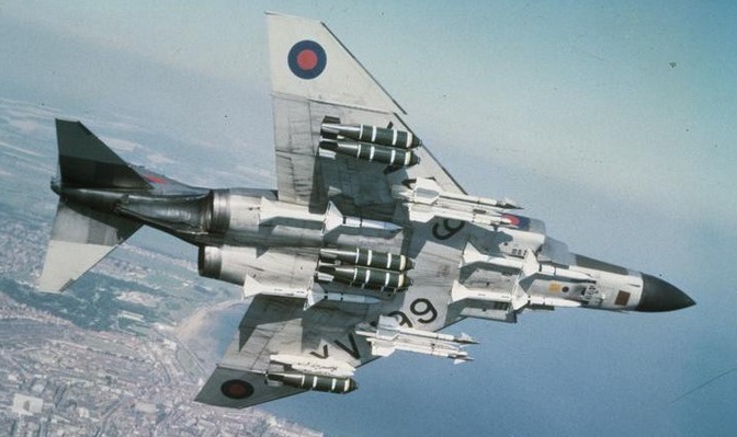
The F-4K was developed for the UK’s Royal Navy and the F-4M for the Royal Air Force, though both were operated by the RAF which, with expanded commitments following the 1982 Falklands war, has also inherited 15 ex-US Navy F-4Js.
Those supplied to the Royal Navy (F-4K) were powered by Rolls Royce Spey turbofan engines. Two versions of the Rolls Royce Spey-powered Phantom entered service with the Royal Air Force. The FG1 (the version also used by the Royal Navy) in the interceptor role and the FGR2 in the ground attack and tactical reconnaissance role in Germany. From 1977, all the Royal Air Force Phantoms were used exclusively as interceptor fighters over United Kingdom air-space.
Originally, adapting F-4B to smaller British carriers seemed to require only a change from GE J79 to RR Spey engines would be needed. By 1964, more modifications were required including drooped ailerons to slow landing speed, extended wing area and fuel capacity and others. These delayed closing the deal to reconfigure feasibility and costs.
Great Britain bought fifty two Phantom FG1s and 118 Phantom FGR2s.
With the deployment of Phantoms to the South Atlantic in 1982 an additional order for 15 Phantoms was placed. These were second hand United States Navy F-4Js fitted with General Electric F-79 engines. After an extensive refurbishment and the fitting of some British equipment they were designated F-4J(UK).
The collapse of the threat from the Eastern Europe led to an accelerated run down of the Phantom fleet and the last unit disbanded at the end of September 1992.
The German Luftwaffe was the biggest operator of the Phantom flying the F-4F ICE upgrade until the Eurofighter takes over its air defence role. Turkey and Greece were also still flying the F-4, their F-4E aircraft undergoing extensive upgrade work. Turkey was upgrading them to F-4E/2020 Terminator in cooperation with IAI. The Greek Air Force (HAF) upgrade program is known as Peace Icarus I&II and covered 40 aircraft. They also operated a number of RF-4 photo reconnaissance aircraft.
The Air National Guard was the last US operator of the F-4 until retirement in 1995/1996.
The EF-4B designation went to one airframe used for ECM training, and two modified, development airframes bore the NF-4B designation.
The F-4N is an upgraded ‘rebuild’ of the F-4B, and has in turn been converted to the QF-4N drone. The F-4S is an upgraded F-4J with wing manoeuvre slats and was the final Phantom variant to serve aboard an aircraft carrier, with VF-151 and -161 aboard the USS Midway.
Production ended in America after more than 5,050 had been delivered.
Operators: US Air Force, US Navy, US Marine Corps, Germany, United Kingdom, Turkey, Greece, Spain, Egypt, Iran, Israel, Australia, Japan, South Korea
By March 2000, 336 F4E and F4G airframes – most at Davis Monthan AFB, Arizona – had been identified for conversion to drones. The newer “G” and “E” models were chosen because their airframes typically have time remaining before USAF-regulated depot maintenance would be required for safe flight.
The fighters are flown to Mojave, Calif, where BAE Systems removes certain equipment and installs a drone autopilot, new computers, improved navigation systems and an onboard destruction package. Tails and wingtips are painted orange for easier visual acquisition during live-fire missions. Converting each F4 to a drone configuration costs approximately $2 million. Once QF-4s arrive it Tyndall AFB, they are classified in one of three roles: A manned flyer, flyable-storage drone, or a mission-ready drone. Some are sent to an 82nd ATRS detachment at Holloman AFB, N.M., to support Army and other aerial target requirements.
About 14 QF-4s are maintained as “manned” aircraft and flown regularly by USAF and Lockheed Martin pilots for mission rehearsals, proficiency and pilot upgrades.
Tyndall Air Force Base, Fla. (AFNS) — The 82nd Aerial Target Squadron received the last of the “new” QF-4 aerial targets on 19 November 2013.
The QF-4, Aircraft 68-0599, spent more than 20 years in the Air Force “Boneyard” at Davis-Monthan Air Force Base, Ariz., before being brought back to life for one last mission.
The supersonic, reusable QF-4 provides a realistic full-scale target for air-to-air weapons system evaluation, development and testing. Since the QF-4 replaced the QF-106 in 1998, more than 300 found a new purpose. The Phantoms began returning to work after the 309th Aerospace Maintenance and Regeneration Group reinstalled the parts to the aircrafts making them serviceable again. The next step involved contractors BAE Systems converting the F-4 to the QF-4, which would be flown remotely by highly-trained civil service pilots with an average of 4,000 flight hours.
The teamwork of contractors, civilian and military members contributed to more than 16,000 manned and 600 unmanned QF-4 missions. Ultimately, 250 of the Phantoms succeeded in their missions and been successively destroyed over the Gulf of Mexico and the ranges near Holloman Air Force Base, NM.
There are only about 60 QF-4s remaining in the program both at Tyndall AFB and Holloman AFB by the end of 2013. The limited availability of F-4s and the continuing advancement of fighter aircraft such as the F-22 Raptors are forcing a shift to the fourth generation QF-16, a converted F-16 Fighting Falcon that should be ready for use in 2014.
Production of the Phantom at St Louis eventually totalled 5057 complete machines, the last of which was flown away on Friday 26 October 1979. Eleven further F-4Ejs were provided a knock-down kits to Mitsubishi Industries in Japan, for a total of 5068 complete airframes. Japan brought the eventual total up to 5195 when the last F-4EJ was rolled out in May 1981.
F-4B (F4H-1) Engines: 2 x General Electric J79-GE-2A, 16,150 lb Wing span: 38 ft 5 in (11.7 m) Length: 58 ft 3 in (17.76 m) Height: 16 ft 3 in (4.96 m) Max TO wt: 54,600 lb (24,765 kg) Internal fuel capacity: 3665 gal External fuel capacity: 500 gal (under fuse) / 2×300 gal underwing. Max level speed: M2+.
F-4C (F-110A) Engine : 2 x General Electric J79-GE-8 (4950/7711kp), 75645 N Length : 62.828 ft / 19.15 m Height : 16.273 ft / 4.96 m Wingspan : 38.386 ft / 11.7 m Wing area : 530.019 sq.ft. / 49.24 sq.m Max take off weight : 54606.8 lb / 24765.0 kg Weight empty : 28003.5 lb / 12700.0 kg Max. speed : 1376 kt / 2548 km/h Cruising speed : 499 kt / 925 km/h Service ceiling : 70997 ft / 21640 m Cruising altitude : 40026 ft / 12200 m Wing load : 103.12 lb/sq.ft / 503.0 kg/sq.m Maximum range : 1998 nm / 3700 km Range : 1998 nm / 3700 km Range (max. weight) : 783 nm / 1450 km Crew : 2 Armament : 4x AIM 7E Sparrow III, 4x AIM 9 Sidewinder / 16,000 lb / 7250kg ext.
F-4D
F-4E Power Plant: Two General Electric J79-GE-17A axial-flow turbojets each with a normal continuous rating of 11,110 lb St (5044 kgp), a max continuous (30-mm) rating of 11,870 lb st (5 390 kgp) and an afterburner rating of 17,900 lb st (8 127 kgp) Fuel capacity, 1 225 US gal (46371) in seven bladder tanks in fuselage, 630 US gal (23851) in two integral wing tanks and up to 1,340 US gal (50721) in three drop tanks; max possible capacity, 3,333 US gal (12615 lt) Max speed, Mach= 2.17, 1,245 kts (2304km/h) at 36,000 ft (10 973 m) Max rate of climb (clean), 49,800 ft/mm (253 m/sec) Service ceiling (clean), 58,750 ft (17 907 m) Ferry range, 1,401 naut mls (2593 km) Range w/max.payload: 700 km / 435 miles Empty weight, 30,328 lb (13770 kg) Basic weight, 31,853 lb (14461 kg) Design weight (for 8.5g subsonic, 6.5g supersonic), 37,500 lb (17 025 kg) Design take-off weight (7.75g subsonic, 5.93g supersonic), 58,000 lb (26 332 kg) Max take-off weight, (5.17g subsonic, 3.95g supersonic), 61,795 lb (28 055 kg). Max. payload : 31476.4 lb / 14275.0 kg Span, 38 ft 4 in (11,68 m) Span folded, 27 ft 6 in (8,38 m) Length, 63 ft 0 in (19,20 m) Height, 16 ft 5 in (5,00 m) Undercarriage track, 17 ft 9 in (5,41 m) Wing area, 530 sq ft (49,24 sq.m) Aspect ratio, 2.82:1 Dihedral, zero on centre wing, 12 deg on outer panels Sweepback, 45 deg at quarter chord. Landing speed : 148 kt / 275 km/h Cruising speed : 504 kt / 934 km/h Initial climb rate: 29921.26 ft/min / 152.00 m/s Wing load : 114.6 lb/sq.ft / 559.0 kg/sq.m Crew : 2 Hardpoints: 9 Armament: One General Electric M61A1 multi-barrel 20-mm cannon under forward fuselage with 640 rounds. Provision for four AIM-7E-2 Sparrow missiles semi-recessed under fuselage. Centre line pylon up to 2,170-lb (986-kg) + up to 3,020-lb (1 371-kg) + four wing pylons / one AGM-45A Shrike or one Walleye ASM + inner pylons two AIM-4D Falcon or two AIM-9D or -9E Sidewinder AAMs.
F-4E(S)
F-4EJ Wing span: 38 ft 5 in (11.71 m) Max speed: M2.2.
F-4F Phantom II Engines: 2 x GE J79-GE-17A, 17,900 lb / 8119 kg thrust Span: 38 ft 7.5 in / 11.77 m Length: 63 ft 0 in / 19.20 m Height: 16 ft 5.5 in / 5.02 m Empty weight: 31,328 lb / 13,757 kg MTOW: 61,795 lb / 28,630 kg Wing area: 530 sq.ft / 49.24 sq.m Speed: 1433 mph / 2301 kph Ceiling: 58,750 ft / 17,905 m Range: 1424 mi / 2280 km Armament: 1 x 20mm Vulcan Bombload: 16,000 lb / 7257 kg ROC: 30,000 fpm / 9145 m/min Tactical radius: 700 mi / 1125 km Seats: 2
F-4G Wild Weasel’ Phantom Powerplant: two 8119-kg (17,900-1b) thrust General Electric J79-GE-17A afterburning turbojets. Maximum speed with external stores Mach 2 + Initial climb rate at maximum take-off weight 2003 m (6,570 ft per minute) Service ceiling 16580 m (54,400 ft) Combat radius 1145 km (712 miles). Empty weight 13757 kg (30,328 lb) Maximum take-off weight 28030 kg (61.795 lb) Span 11.77 m (38 ft 7½ in) Length 19,20 m (63 ft 0 in) Height 5.02 m (16 ft 5½ in) Wing area 49.2 sq.m (530 sq ft). Hardpoints: 7 Armament: up to 7258 kg (16, 000 lb)
F-4J
F-4J(UK)
F-4K (FG.Mk 1)
F-4M (FGR.Mk 2)
F-4N
F-4S
EF-4C
RF-4B
RF-4C Powerplant: two General Electric J79GE-15 turbojets, 7711-kg (17,000-lb) afterburning thrust. Maximum speed at low level 1464 km/h (910 mph) or Mach 1.19 Maximum speed at altitude 2414 kph (1,500 mph) or Mach 2.27 Ferry range 3700 km (2,300 miles) Empty weight 13290 kg (29,300 lb) Maximum take-off 26309 kg (58, 000 lb) Span 11, 71 m (38 ft 5 in) Length 19.20 m (63 ft 0 in) Height 5.02 m (16 ft 5 1/2 in) Wing area 49.24 sq.m (530 sq ft)
McDonnell Aircraft Co had invested in Platt-LePage Aircraft in mid-1942, in exchange for having McDonnell personnel learn helicopter design. In 1943 McDonnell authorized Constantine M. Zakhartchenko and a small group of engineers to undertake research on design and construction of rotors. He was appraised of Platt-LePage’s preliminary work on a twin-engined, twin-rotor helicopter to meet Army requirements. Although that PL-9 design eventually proved unsuccessful in the Army competition (the AAF selected the Kellet XR-10), it fared better in a different guise as McDonnell, in return for an increase in his investment as finalized in June 1944, obtained Platt-LePage’s agreement allowing the McDonnell Aircraft Corporation to initiate the parallel development of the twin-engined, twin-rotor concept.
On the strength of both this agreement and the work accomplished by Zakhartchenko’s team, McDonnell proposed a helicopter of this design to the Navy to serve either as a testbed or as an anti-submarine warfare platform. As a testbed, the proposed Model 65 was intended to be used for the study of the effects of rotor diameter, disk loading, variations in rotor blade flap and lag angles, and other variables. In the ASW role, it was to be able to carry an adequate load of detection gear and weapons.
Considering the side-by-side rotor arrangement proposed by McDonnell to be a most suitable configuration for large helicopters capable of operating in the ASW role, the Bureau of Aeronautics issued a Letter of Intent on 15 May, 1944, covering the design, construction, and testing of one XHJD-1. This Letter of Intent was confirmed on 23 March, 1945, when Contract NOa(s)-3703 was awarded.
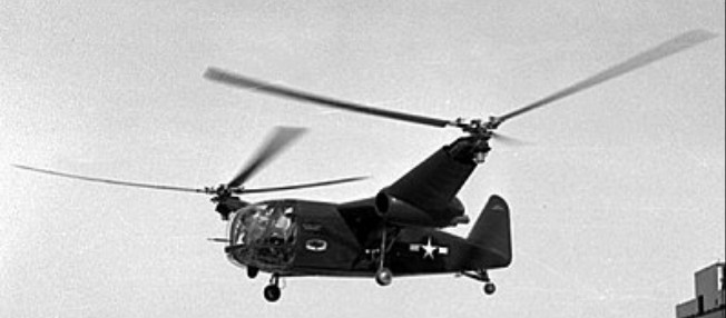
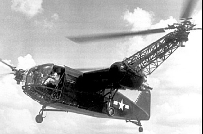
At the time of contract award, design of the Whirlaway, entrusted to a team led by Constantine Zakhartchenko, was well underway and ground testing was begun early in 1946. Piloted by Charles R. Wood Jr, the XHJD-1 made its first hover flight at Lambert Field, St Louis, on 27 April, 1946.
Designed to carry up to ten occupants but normally flown as a two-seater with up to 816kg of test instrumentation, the Whirlaway was fitted with twin side-by-side rotors mounted on pylons extending outboard of the engine nacelles. The nacelles, each housing a 450hp Pratt & Whitney R-985-AN-14B seven-cylinder radial engine, were attached to short wings which supported approximately 10 per cent of the gross weight during cruise and as much as 30 per cent of the weight in power-off autorotation, with consequent substantial improvement in overall performance efficiency. This feature, combined with the ability to transmit power from either engine to both rotors by transmissions and gear boxes, enabled the XHJH-1 to maintain level flight at full gross weight on the power of only one engine.
From April 1946 until June 1951, the XHJD-1 was used for numerous flying research tests including the evaluation of performance, stability balance and vibration characteristics peculiar to its twin-rotor configuration. In the process, the Whirlaway had its original 15.24-m diameter rotors replaced by rotors of varying diameters and had a braced tailplane with externally balanced control surfaces added before translation flights began. Once vibration and resonance problems with its unsynchromzed three-blade rotors were alleviated through the use of shock-absorbing rotor mounts, the XHJD-1 was considered to handle well and was flown some 250 hours without serious mishap. It was flown not only by McDonnell and Navy pilots but after being fitted with a rescue winch, was also evaluated in November 1949 by USAF pilots from the Arctic Rescue Helicopter Board.
As helicopter technology had made significant progress since development of the Whirlaway had been initiated, neither the XHJD-1 nor its proposed Model 65C development was put into production. Upon completion of its trials programme, the XHJD-1 – the first helicopter to bear the McDonnell name and the world’s first successful twin-engined, twin-rotor helicopter was donated to the National Air and Space Museum.
XHJD-1 Engine: 2 x Pratt & Whitney R-985-AN-14B Wasp Junior, 336kW / 450 hp Rotor diameter: 14.02-15.24m depending on configuration Overall span: 26.52m Fuselage length: 9.8m Height: 3.73m Empty weight: 3629kg Loaded weight: 4990kg Rotor loading: 13.7-16.2kg/sq.m Power loading: 5.5kg/hp Maximum speed at 1525m: 193 kph Cruising speed: 145km/h Rate of climb: 6.6m/s Absolute ceiling: 3930m Range: 485km
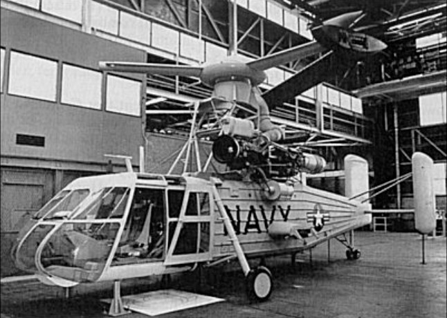
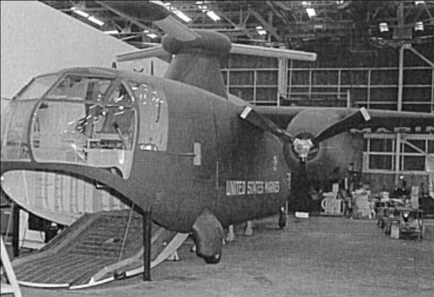
The McDonnell Model 86 was the first helicopter specially designed for the Navy vert-rep (vertical replenishment) mission – carrying supplies and ammunition between ships—and for the Marine logistic support mission—carrying heavy loads for short distances from ship-to-shore or from marshalling areas ashore to front-line units.
Emphasis was placed during its design on extreme simplicity, ease of maintenance, and good flying characteristics while carrying underslung loads of up to 6804kg when operating at normal gross weight, or 9979kg when operating at overload gross weight. The powerplant installation, derived from that developed for the XHRH-1, consisted of two 3750eshp Allison XT56-A-2 turbines mounted atop the fuselage and providing compressed-air to the 726kg thrust McDonnell 12JP20 pressure jet at the extremity of each rotor blade. The crew of two consisted of a pilot on the starboard side and an aft-facing winch operator to port. There was no provision for carrying loads internally. Loads were to be carried externally on a sling, in a net, or in a specially-developed pod. This pod was to be fitted with a detachable tail unit to stabilize the load in flight and with large wheels to enable it to be towed on uneven ground after it had been delivered to forward bases. Consideration was also given to using the Fairchild pod which had been designed for the XC-120 twin-engined cargo aircraft.
Three XHCH-1 prototypes (BuNos 138654/138656) were ordered on 11 April, 1952, under Contract NOa(s)52-947 and a mock-up was inspected on 22 and 23 May, 1953. However, the programme was later cut back due to lack of funds. No prototypes were completed but a much revised mock-up was inspected on 15 and 16 November, 1956, and a full-scale rotor was tested on a hot-whirling bench beginning in December 1957. Additional budget cuts forced the Navy to terminate the contract on 18 January, 1959, before completion of a prototype. Nevertheless, McDonnell kept working on the Model 86 sky crane until June 1961.
XHCH-1 Rotor diameter: 19.81m Length: 11.45m Height: 5.07m Empty weight: 6749kg Loaded weight: 16026kg Maximum weight: 19051kg Maximum speed at sea level: 185km/h Rate of climb: 16m/s Hover ceiling out of ground effect: 2285m Combat radius: 37km
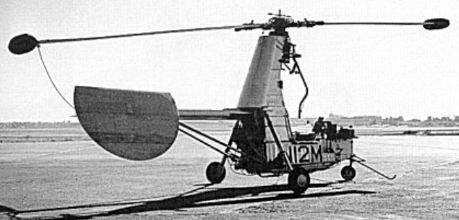
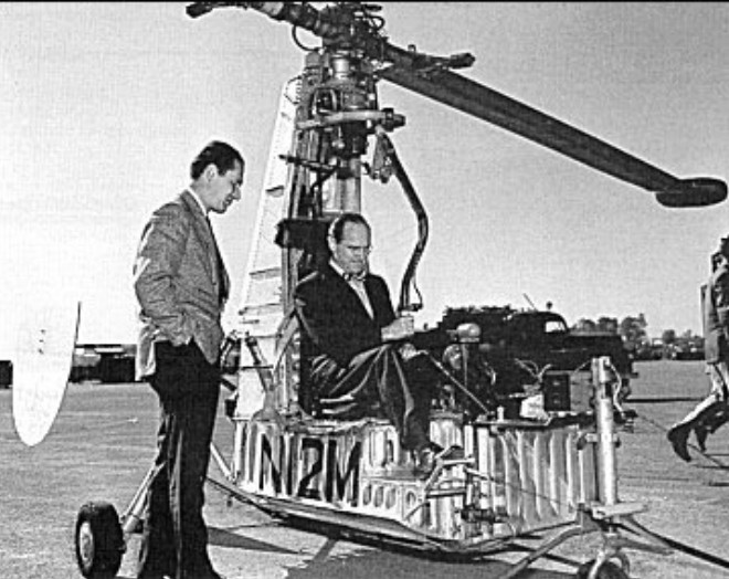
In 1950, after trials with the XH-20 had been terminated, McDonnell engineers remained convinced that for certain specialized applications the intrinsic simplicity of this system would outweigh its uneconomical fuel consumption rate. Hence, after failing to attract the interest of the Army in a proposed light scout and observation vehicle using a ramjet-driven rotor, they turned their attention to the agricultural market in the belief that an easily maintained, low cost helicopter would find a ready market.
As described in a specification report dated 26 September, 1950, the Model 79 was essentially similar in concept and construction to the Model 38 (XH-20) but was somewhat larger with the diameter of the two-bladed rotor being increased from 5.49m to 8.23m. It differed further from the Model 38 in having tail surfaces consisting of a fixed ground adjustable tailplane and a universally mounted movable rudder. Open accommodation was provided for a pilot, and alternate alighting gears, consisting of either a tricycle gear or twin skids, were offered. Power was provided by a pair of McDonnell 8RJ4 ramjets, one at the tip of each rotor blade, and 379 litres of fuel was carried in two tanks. For ferry purposes auxiliary tanks could be fitted to increase fuel capacity to 681 litres.
Designed as a utility helicopter, the Model 79 was intended to be used for pest or weed control, defoliation, fertilizing, seeding, or many other varied uses such as carrying mail or cargo. To that end, it could be fitted with either (1) dual liquid chemical tanks with a total capacity of 439 litres and dual spray booms; (2) dual dust or seed bins with a total capacity of 0.44cu.m and a dust outlet pointing downward and aft of the rotor disc; or (3) dual mail or light cargo bins with a total volume of 1.13cu.m. As a further alternative, the design provided for the installation, either during construction or as rapid modification kits, of cockpit floor extensions and removable plastic panels to convert the single-seat Model 79 into the two-seat Model 79A with dual controls.
Charles R. Wood Jr. first flew the single seat Model 79 demonstrator, which was registered N12M, on 26 March, 1952. Although trials proved relatively uneventful and confirmed that the basic design was sound and easy to fly and maintain, development of the Model 79 had to be abandoned in mid-1953 as the type had failed to attract commercial interest due to high fuel consumption rate and noise level.
Steve Cole 15.03.2012 My Grandfather, Willis Cole Jr. worked for McDonnell. Somehow he acquired most of Big Henry when the project was cancelled. There are pictures of it sitting in the family driveway. Up until a few years ago, the landing gear, instrument panel and a piece of the fuselage (with the N12M number) were still floating around his garage. Willis Cole Jr. passed away 3-16-2012.
Model 79 Rotor diameter: 8.23m Fuselage length: 4.72m Height: 2.54m Empty weight: 293kg Loaded weight: 816kg Maximum weight: 907kg Maximum speed: 138km/h Rate of climb: 5m/s Hover ceiling in ground effect: 1160m Service ceiling: 3050m Endurance: 62 min
Design of the Model 78 was started in 1950 in answer to a request for proposals for an assault transport helicopter which had been issued by the Navy Department on behalf of the US Marine Corps. Intended to operate from CVE-105 class (USS Commencement Bay) carriers, the new helicopter was to fit on 13.41m by 12.80m deck elevators. Its primary mission was to carry 30 troops to objectives up to 100 naut miles away and return to the carrier without the need to refuel ashore.
To fulfil what were then most demanding requirements, McDonnell designed a compound helicopter with a three-bladed rotor and short wings on which were mounted two 3507shp Allison XT56-A-4 turbines. For vertical flight, air from engine-driven auxiliary compressors was to be ducted to 726kg thrust McDonnell 12JP20 pressure jets, one at the extremity of each rotor. For forward flight, each engine was to drive a three-bladed propeller, with transition from helicopter flight mode to conventional flight being made by transferring power from the auxiliary compressors to the propellers as soon as the forward speed exceeded the stalled speed of the wing. Normal accommodation was to have been provided for a crew of two and 30 fully-equipped troops. Alternatively, accommodation could have been provided for 36 troops or 24 litter patients, or two Jeep-sized vehicles could have been carried internally. Larger loads (up to a maximum weight of 5224kg) could be carried externally. Another noteworthy design feature was the inclusion of a hydraulically-operated loading ramp in the forward fuselage, beneath the cockpit. Folding wings, rotor blades, and tail unit were to have enabled the Model 78 to fit on the deck elevators of CVE-105 carriers.
The Navy selected the McDonnell design on 15 March, 1951, and two and a half months later issued a Letter of Intent for three XHRH-1 prototypes (BuNos 133736/133738) to be built under Contract N0a(s)-51-1201. A full-scale mock-up of the XHRH-1 was inspected on 22 and 23 October, 1952, and construction of the prototypes was begun. However, after the Korean War had ended, budget cuts and concern over anticipated developmental problems led to the cancellation of the contract before completion of a single XHRH-1. All work on the project ended in April 1954.
XHRH-1 Rotor diameter: 19.81m Wingspan: 13.72m Length with rotor blades and tail folded: 16.33m Height: 5.09m Wing area: 30.84 sq.m Empty weight: 8695kg Loaded weight: 13795kg Maximum weight: 16329kg Maximum speed at sea level: 444km/h Climb rate: 12m/s Hover ceiling out of ground effect: 3050m Combat radius: 185km