Conceived as a light utility transport, the twin-engined low-wing Yakolev Yak-6 was largely of wooden construction and flown for the first time in June 1942; it had retractable tailwheel landing gear and accommodated two crew and four passengers. An NBB (or short-range night bomber) version had external racks for five 100kg bombs under the fuselage and provision for a single 7.7mm ShKAS machine-gun, but the Yak-6 could also be equipped to carry stores or freight (including a 500kg external load) or for use as an ambulance aircraft, glider tug or close-support aircraft carrying 10 RS-82 rockets. Often flown with the main landing gear units locked down, the Yak-6 was also used to supply partisans, and by 1944 most operational units had one of these aircraft to ferry personnel between bases. Production totalled about 1,000. The Yak-6M was an improved version which finally led to the somewhat larger Yak-8, the prototype of which was first flown at the beginning of 1944. This was to have been a dedicated transport, essentially for military use, with accommodation for up to six passengers, but in the absence of anticipated higher-power engines its performance was disappointing and no series production ever took place.
Engines: 2 x M-11F, 103kW Max take-off weight: 2350 kg / 5181 lb Wingspan: 14.0 m / 46 ft 11 in Length: 10.4 m / 34 ft 1 in Wing area: 29.6 sq.m / 318.61 sq ft Max. speed: 180 km/h / 112 mph Cruise speed: 150 km/h / 93 mph Range: 880 km / 547 miles Armament: 1 machine-guns Bombload: 500kg Crew: 2 Passengers: 6
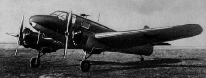
In 1938, the UV-VS (Upravlenie Voenno-vozdushnikh Sil – Administration of the Air Force) formulated a requirement for a two-seat multi-role high-speed combat aircraft. To meet this demand, the OKB (Experimental Construction Bureau) headed by Aleksandr S Yakolev evolved the Ya-22, or Samolet 22. An aerodynamically clean, two-seat low-wing cantilever monoplane of mixed construction and powered by two 960hp M-103A (V Ya Klimov-developed two-speed supercharged derivative of the Hispano-Suiza 12Y) 12-cylinder Vee-type engines, the Ya-22 was proposed in three dedicated versions: long-range escort fighter, short-range bomber and tactical reconnaissance aircraft. Prototypes of all three variants were built simultaneously, the first to fly being the fighter, which, assigned the NKAP (State Commissariat for Aviation Industry) designation I-29, made its maiden flight on 22 February.
Yakolev was then instructed to modify the design to serve as a bomber, the aircraft being redesignated BB-22 (blizhnii bombardirovshchik or short-range bomber). This resulted in major revisions of accommodation, armament and fuel storage, plus the provision of an internal bomb bay. The BB-22 bomber and R-12 reconnaissance prototypes differed from the I-29 primarily in that the fuel tank immediately aft of the cockpit was supplanted by a bay accommodating either eight 50kg bombs in the BB-22 or photo-flashes (for use in conjunction with a single AFA-13 camera) in the R-12. The I-29 had twin 20mm ShVAK cannon in fairings beneath the forward fuselage and a single 7.62mm ShKAS for the aft-positioned observer/navigator, deployment of this gun being permitted by lowering of the aft-fuselage top decking. On 15 March 1939, shortly after commencement of flight testing, Yosif Stalin personally decided to order production of the bomber variant (as the M-105-powered Yak-2) to the exclusion of both fighter and reconnaissance versions.
The first series BB-22 was completed on 31 December 1939 and flown on skis on 20 February 1940. By that time two factories were in production and experimental variants – the R-12 photographic reconnaissance aircraft and I-29 (or BB-22IS) long-range escort fighter – were being prepared for test flights. The BB-22 was redesignated Yak-2 at the end of 1940, and as powered by two 716kW M-103 Vee engines had a maximum speed of 530km/h at sea level service ceiling of 8800m and range of 800km. In 1940 the basic design was further refined to improve the crew positions, field of view and armour protection; the M-105 engine was introduced with better protection for the fuel system, and provisions were made for external bomb racks. Then redesignated Yak-4, the aircraft entered production in the autumn of 1940 and about 600 of both versions were built, the majority of them Yak-4s . They were not particularly successful in service, many of them being lost in the early days of the German invasion.
Ya-22 Max take-off weight: 5023 kg / 11074 lb Empty weight: 3796 kg / 8369 lb Wingspan: 14.00 m / 46 ft 11 in Length: 10.18 m / 33 ft 5 in Height: 3.30 m / 11 ft 10 in Wing area: 29.40 sq.m / 316.46 sq ft Max. speed: 567 km/h / 352 mph Range: 1050 km / 652 miles
Yak-4 Engine: 2 x M-105R, 810kW Max take-off weight: 5245 kg / 11563 lb Wingspan: 14.0 m / 46 ft 11 in Length: 10.2 m / 33 ft 6 in Wing area: 32.0 sq.m / 344.44 sq ft Max. speed: 530 km/h / 329 mph Ceiling: 9500 m / 31150 ft Range w/max.fuel: 1600 km / 994 miles Range w/max.payload: 800 km / 497 miles Armament: 1 x 7.62mm machine-gun Bombload: 400 kg Crew: 2
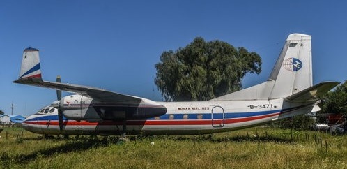
An Antonov An-24 copy. Built in Xian, the Y-7 is an improved version of the Soviet An-24 twin-turboprop transport. The Y-7 received its Chinese certificate of airworthiness in 1980, and has a wider fuselage and larger wing than the An-24, combined with Chinese engines and equipment. Of the first 24 Y-7s built, about ten were delivered for military use.
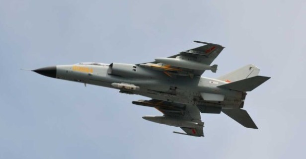
In the early 1970s, China was looking for a fighter-bomber to replace the H-5 (Il-28) and Q-5. Initially, China looked abroad for joint solutions, but when these efforts fell through, a program was started to develop a domestic design. Requirements soon emerged from the PLAAF and PLANAF requesting separate configurations. The PLAAF wanted side-by-side seating, terrain-following radar, and an extensive ECM suite, while the PLANAF requested tandem seating, all-weather performance, and reconnaissance capabilities. The PLAAF variant would be dropped fairly early on and by the end of 1988, Xian had developed a two-seat design with a shoulder mounted wing, powered by two Rolls-Royce Spey engines. While it was equipped with a powerful radar capable of tracking both aircraft and ships, the original design lacked any significant air-to-air capabilities. The aircraft was not without its teething issues. Flight testing was filled with major (often near catastrophic) malfunctions. The first flight ended early when violent vibrations shook off the majority of the cockpit instrumentation, and later tests ended when massive fuel leaks almost caused the aircraft to run out of fuel in flight. When the aircraft began operational evaluations, one aircraft lost its entire rudder in flight, making a successful emergency landing. Despite all of the issues, the PLAAF soon requested its own variant of the JH-7. Designated the JH-7A, the new aircraft was to have a stronger airframe and higher payload than the JH-7 and the capability to deploy various precision-guided weapons.
JH-7
After extensive testing and redesigns, JH-7s began to enter service with the PLANAF and PLAAF in 2004. Over 200 have entered service, providing the Chinese with a fairly capable replacement to their MiG-19-derived Q-5s. JH-7As continue to be upgraded with systems such as a newly developed helmet-mounted sight. Meanwhile, the Chinese are working on a more extensive upgrade to the design, designated the JH-7B. The JH-7B is to feature upgraded avionics, a reduced frontal RCS, aerial refueling capabilities, and upgraded engines producing 15% more thrust. Plans called for the JH-7B to enter production in 2015.
Xian JH-7A
China revealed a 20-year-old fighter/bomber at the Air Show China ‘98, held at Zhuhai. The aircraft, the FBC-1 Flying Leopard, is an export version of the JH-7 twin-seat strike fighter and actually flew in 1989, though its development programme dates back to the 1970s. This was the first time the aircraft has been flown in public. The aircraft was developed by the Xian Aircraft Design and Research Institute (ADRT) and is capable of Mach 1.7, and has a range of 890 nm.
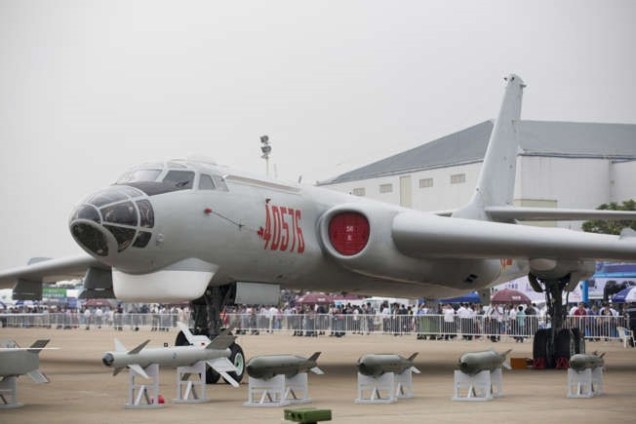
A 1961 split ending Soviet assistance, left the Chinese with the task of getting the Tu-16 into production as the Hongzhaji-6 (bomber aircraft no. 6). The Chinese spent two years in reverse-engineering the Tu-16 and its Mikulin AM-3 turbojets, and started production in 1962 for first deliveries in 1968. Since that time the Air Force of the People’s Liberation Army has received more than 100 H-6s for the strategic free-fall bomber and anti-ship roles, the latter with two missiles carried under the wings. Principal version – H-6 (sole production model in several variants up to at least the H-6D, or H-6 IV, which is believed to be the anti-ship type). Low-rate production of the Tu-16 Badger continues at Xian in 1987, and the H-6 is still the mainstay of China’s strategic nuclear bomber force. Local developments of the design include an anti-shipping version carrying C601 missiles and equipped with an under-nose search radar. A four-engined variant of the H-6 has also been reported. Customer: China 120+
After decades of service, Xian finally performed a major overhaul of their H-6 (Tu-16) around the turn of the century. While previous modifications merely upgraded avionics of the design, the new variant developed, the H-6K, redesigned the airframe to extensively use composites, and replaced the old Chinese engines with Russian-made Saturn D-30KP turbofans. As Chinese bomber doctrine has long since shifted to the use of bombers as cruise-missile carriers, the bomb bay was replaced with larger fuel tanks, and the obsolete tailgun armament was replaced with an extensive ECM suite. Similarly, the glazed navigator position was replaced with a more powerful targeting radar. The H-6K first flew in January 2007, and after two years of testing, the bomber entered service with a combat radius nearly double that of the original H-6.
China International Aviation & Aerospace Exhibition in Zhuhai, China, 2014
About 150 of its bombers have been built, and about 120 were still operational in 2025. The H-6 has been upgraded to carry modern weapons, including hypersonic and nuclear-capable missiles.
China sold H-6s to both Egypt and Iraq, but those countries no longer have their bombers operational. According to the Center for Strategic and International Studies, Iraq’s four H-6s were destroyed while in service.
The H-6 has four crew and is powered by two Soloviev D-30KP-2 turbofan engines, each with 27,000 pounds of thrust. Its top speed is 670 mph, and its cruising speed is 477 mph. Its combat range is 2,200 miles. It can also carry 26,500 pounds of bombs, both guided and unguided (dumb bombs), but no longer carries free-fall nuclear bombs, as the H-6 could not be relied upon to penetrate an enemy’s air space.
Xian H-6 Type: six-seat strategic medium bomber and anti-ship missile carrier Engines: 2 x 20,944-lb (9,500-kg) thrust Xian WP-8 turbojets Maximum speed 616 mph (991 km/h) at 19,685 ft (6,000 m) Initial climb rate 4,100 ft (1,250 m) per minute Service ceiling 40,355 ft (12,300 m) Range 2,983 miles (4,800 km) with an 8,157-lb (3,700-kg) warload Empty weight about 82,010 lb (37,200 kg) Maximum take-off weight 158,733+ lb (72,000+ kg) Wing span 108 ft 1.2 in (32.95 m) Length 114 ft 2.1 in (34.80 m) Height 35 ft 5.2 in (10.80 m) Wing area 1,772.87 sq ft (164.70 sq.m) Armament: four 23-mm cannon in twin-gun dorsal and tail turrets, and up to 19,842 lb (9,000 kg) of bombs
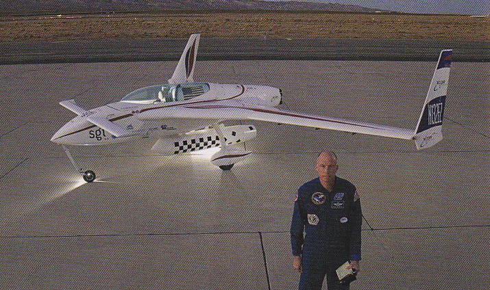
A rocket powered version of the Long-Ez flew twice at Mojave in 2002. Its twin rocket motors of 400 lb thrust each burned for less than three minutes after which it took seven minutes to glide to landing. It is fuelled by isopropyl alcohol and liquid oxygen. The engines can be shut-down and restarted in flight.
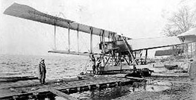
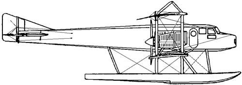
One of the largest seaplanes then in existence, the plane was built by Witteman-Lewis Aircraft Corp in 1923 for an intended transatlantic flight by the two Swedish aeronauts.
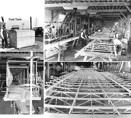
Sundstedt-designed, linen-covered balsawood floats of 32′ length, all else was of ash and spruce construction; 750-gallon fuel tanks.
It crashed in a test flight in Feb 1919 and was considered beyond economical repair.
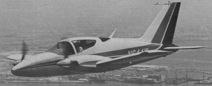
By 1962, George Wing had moved on to the development of John Thorp’s little twin, which eventually became the Wing Derringer. George Wing hired John Thorp to design a high performance two seat twin. Thorp, who had been toying with the idea of hanging two engines on his Sky Skooter (one of which Wing owned), was already primed for the idea. They started with a clean sheet of paper and, using two Continental O 200 engines and fixed pitch props, came up with an airplane that was, for its operating costs, a wonderful performer, first built in 1978. John E Robey designed the major assembly tooling for the Wing Derringer at Olin-Dixon in Coffeyville Ks in the late 1960’s. Derringer project leader was Larry Heuberger.
The prototype carried two special Continental 115 hp IO-200 engines with fuel injection. The cowling was 21.5 inches deep. The prototype N3261G first flew on 1 May 1962, kept throwing prop blades, however, its engine out performance was inadequate, and the tweaked engines were not a realistic choice for a production airplane; and so eventually, production prototypes were equipped with 160 hp Lycoming engines. Originally, the Derringer was equipped with very thin, narrow bladed racing props.
While testing the prototype, the next two units were nearing completion in Torrance, California.
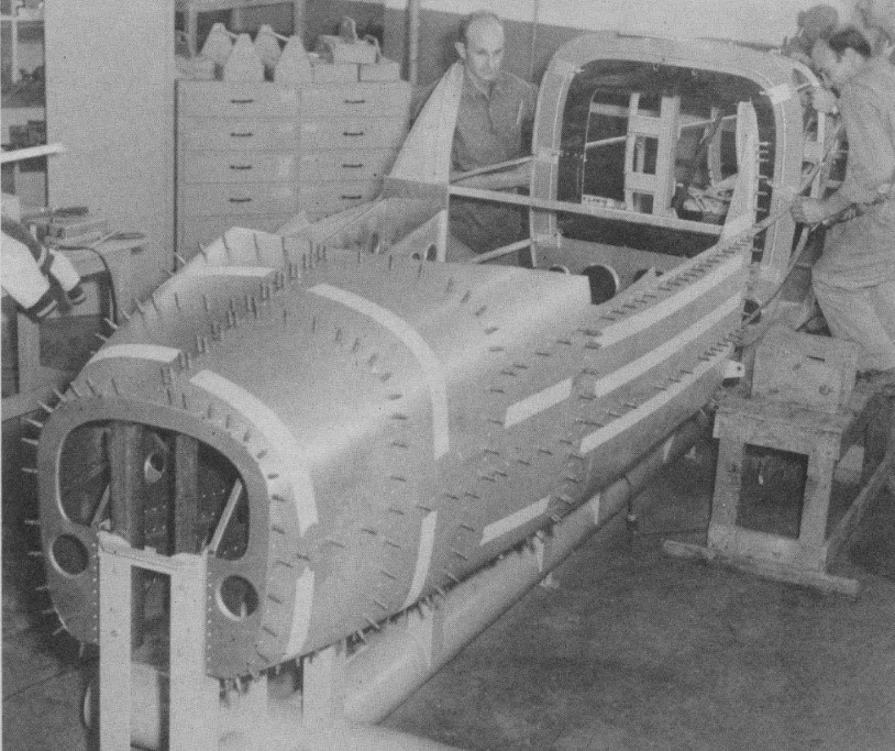
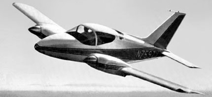
The airplane was a compact two-seater with a huge baggage bay behind the seats, a simple rectangular wing and a fuselage that was all curves from nose to tail. Its structure used stretched chem milled skins throughout. With stretch-formed, chemically-etched skins, the number of metal pieces requied is greatly reduced and labour time is cut accordingly. The Derringer has eight fuselage pieces and there isn’t a flat surface on any of them. There are only 13 major skins in the entire plane with the wing a single wrap-around sheet .064 thich where ribs and attachments occur. Remaining metal is etched away to .032 where no stresses occur. The wing walk for instance is .064. Metal skins start out at .064 or .040, depending on their function, and are etched down to whatever thickness the specs call for.
The flight test and production models, under construction in 1964, were to be equipped with 150 hp Lycoming IO-320 engines that operate on 80/87 octane fuel. The production aircraft would have full-feathering, constant speed, two-blade Hartzell props.
Matched-hole tooling means the Derringer can be assembled with a minimum of jigs and fixtures. All holes were to be in a temperature-controlled room so that the parts for number 2 and 3 aircraft were interchangeable with any others, All skin assembly is butt-jointed and flush riveted.
Derringer no.2
The prototype had a fuselage two inches narrower than the production model and was fitted with a slide-back cover. The prototype had a hand brake while the production craft were to have toe brakes. A simple automotive window motor operates the Saginaw ball and screw system for gear retraction and flap movement.
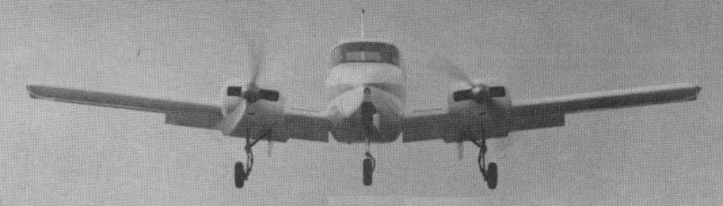
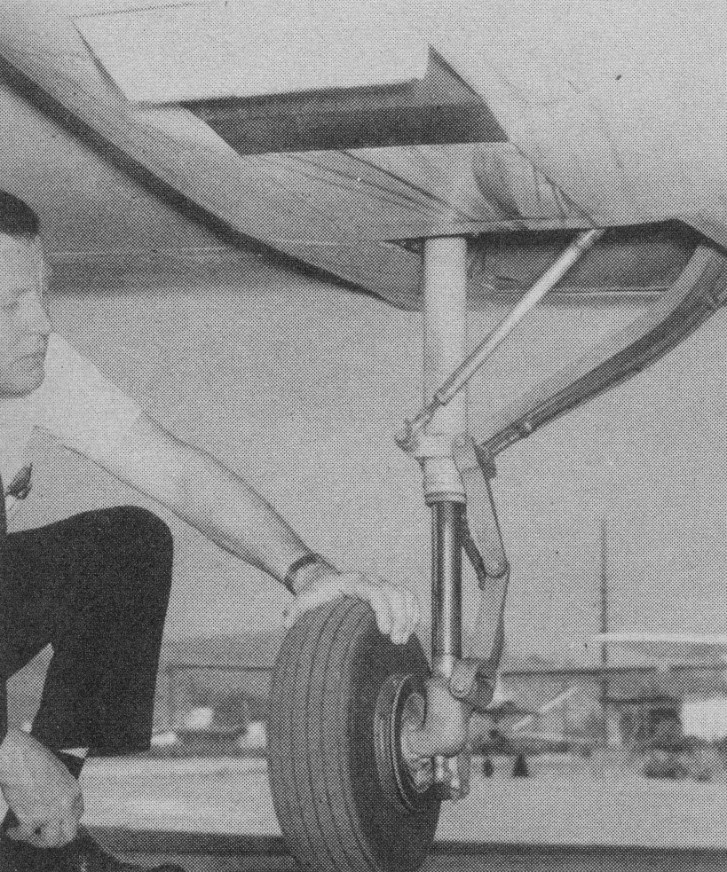
The Derringer undercarriage is fitted with three oleo struts, each with 9 inches of travel.
It would cruise at 190 knots, climbing at 1,700 fpm and boasting a range of over 1,000 nm with reserves.
There is no steering on the ground except with the engines.
Pre-take off check list Fuel on Crossfeed off Trim set Mixture rich Flaps 10 deg Controls free Canopy locked
Landing check list Mixture rich Gear down and locked Flaps as desired
First deliveries were expected in the Spring of 1964, priced at $27,500.
Wing spent $3 million of his own money, $5 million all told, in developing and certificating the airplane.
Wing contracted with a Kansas manufacturing firm, Olin Dixon, to manufacture an initial production of five with 150hp, ATC A9WE, in 1966, and a second production with 160hp. Problems developed, which Olin blamed on Wing and Wing blamed on Olin. Litigation followed. The first 3 if the initial production were built by Wing’s Transland company
In 1979 Wing Aircraft’s two seat Derringer twin seemed to be on the verge of entering the general aviation marketplace at $40,500. Company President George Wing said that the first production Derringer were to be delivered in the fall. The aircraft, which is powered by two 160 horsepower Lycomings, has a book cruise speed of 182 knots at 65 percent power. Sea level rate of climb is 1,700 feet per minute, and the empty weight is 2,100 pounds. An IFR equipped Derringer was to sell for about $100,000.
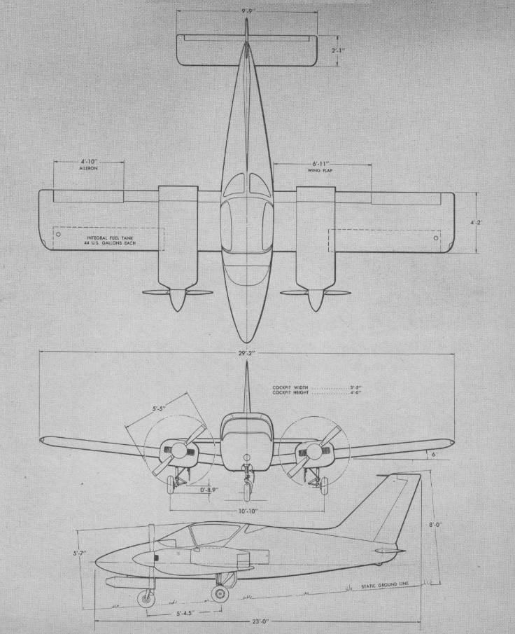
Prototype Engine: Continental IO-200, 115 hp Props: fixed pitch Wingspan: 29 ft 2 in Cabin height: 5 ft 7 in Fin top: 8 ft Fuel capacity: 2 x 44 USG Wing loading: 22.15 lb/sq.ft Liftoff speed: 90 mph TO roll: 700 ft Cruise climb: 130 mph / 1200 fpm UC down max: 125 mph Stall speed: 66 mph SE critial speed: 77 mph Cruise speed 75%: 250mph at 20,000 ft Baggage compartment: 22 cu.ft Baggage door is 10×30 in on thebleft side of the fuselage. Cabin height: 48 in Cabin width: 44 in Cabin length: 98 in Seats: 2 Gear cycling: approx 6 sec
Engine: 2 x Lycoming O-320-B1C, 160 hp TBO: 2000 hrs Prop: Hartzell, 2 blade, variable pitch 66 in Seats: 2 Length: 23 ft Height: 5.8 ft Wingspan: 29.1 ft Wing area: 121 sq.ft Wing aspect ratio: 7 Max ramp wt: 3050 lbs Max take off wt: 3050 lb Standard empty wt: 2100 lb Max useful load: 950 lb Max landing wt: 2900 lb Wing loading: 25.2 lbs/sq.ft Power loading: 9.5 lbs/hp Max useable fuel: 522 lb Climb rate: 1700 fpm @ 104 kt Climb gradient: 981 ft/nm Rate of climb @ 8000 ft: 1015 fpm Service ceiling; 19,600 ft SE climb rate: 420 fpm @ 96 kts SE climb gradient: 263 ft/nm SE ceiling: 8,000 ft Max speed: 202 kt Cruise @ 65% power @ 8,000ft: 182 kt Fuel flow @ 65% power @ 8,000ft: 95 pph Endurance @ 65% power @ 8,000ft: 5.2 hr Stalling speed clean: 70 kt Stall speed gear/flaps down: 63 kt Turbulent air penetration speed: 148 kt
From about 1937, the London-based Willoughby Delta Company was considering the construction of a flying wing airliner. Early in 1939, the Delta 9 was to be a tri-motor monoplane with a span of over 100 ft (30 m) with a thick and wide chord centre section, outboard of which the wing was thicker and much greater in chord, in part forming one of a pair of tail booms that carried the double finned empennage. Its trailing edge was at about 20° to the centre line, continuing forwards then turning through 70° to produce the trailing dge of the outer wing section. This was narrower in chord than the centre section. The Delta 9 was seen as a realistic approximation to a true flying wing, with its advantage of a well-distributed load because of the absence of parts like a fuselage which did not contribute to lift. There was also the intention of producing an aircraft that was essentially stall-free.
The unusual design called for a lot of preparatory wind tunnel work, carried out in the UK at the National Physical Laboratory, the City & Guilds, Farnborough and Queen Mary College, London. Valuable pressure distribution measurements were made in the United States at the Guggenheim Institute of New York University. The results were encouraging, producing for example curves of lift coefficient versus angle of incidence that increased linearly in the normal way and then flattened without the usual decrease in lift associated with the stall. It appeared that, at high speed and low angles the forward part of the wing provided most of the lift, but as the stall approached the rear part contributed more. These results encouraged the company to build the Willoughby Delta 8 to investigate the general aerodynamics of the layout with a smaller aeroplane. The exact name seems to be uncertain: the contemporary (February 1939) Flight article calls it Delta 8, in line with the airliner named as Delta 9, but the registration documents from that January refer to the Delta F and the latter name has been widely used. The design had first been announced in Flight in 1937 as the Delta F. The Delta 8 was not a scale model of the proposed airliner, but the arrangement of its lifting surfaces was similar.
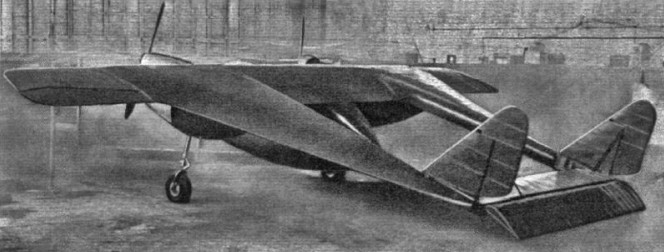
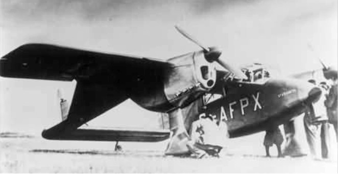
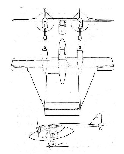
A twin-engined aircraft constructed of wood, the Delta 8 was a twin boom machine. It had a central nacelle, almost elliptical in profile, suspended beneath the wing and containing the glazed cabin. This had tandem seats, accessed via a starboard side door. The wings were built around two conventional transverse spars, unusual only in becoming deeper between the outer boundary of the centre section and the inboard limit of the narrow chord outer sections. The latter carried ailerons over the whole of its trailing edges. The longitudinal spars of the “side wings”, acting as booms, slipped into slots cut into the transverse wing spars. On each side, three longitudinal and very long chord ribs, plus a stiffening diagonal rib that ran to the rear end of the side wing, formed the aerofoil section of these wings. The transverse section of the side wings was also aerofoil shaped, blunt on the inner edge and fine outboard.
Two 125 hp (93 kW) Menasco Pirate C.4 four-cylinder air-cooled inline engines driving two-bladed propellers were mounted against the underside of the wing in steel cradles, at the points where the wing thickness increased. There was a wooden fairing behind, through which ran, to the front spar, the cantilever fixed main undercarriage legs, faired and spatted. The tailplane joined the rearmost inner edges of the side wings, carrying the tailwheel at its centre, and a broad elevator hinged clear of the rest of the structure. Small fins mounted over the tailplane carried balanced rudders, their overall profile almost triangular. The fins were externally braced to the tailplane.
The Delta 9 as described in Flight was expected to carry 36 passengers in two side wing cabins for a gross weight of 38,000 lb on three 1,000 hp engines. The cabins were expected to be have at least a 6 foot headroom but lacked side windows.
The design was constructed at Minster Lovell between Witney and Burford, and first flew on 11 March 1939 at Witney, registered as G-AFPX and named “St Francis”. On 14 May 1939, piloted by A.N. Kingwill, it was demonstrated at the Royal Aeronautical Society’s garden party fly-in at Great West Aerodrome, also at Heston Aerodrome. On 10 July 1939, it crashed near Bicester, killing the pilot Hugh Olley and the Delta’s designer, Percival Willoughby. The crash was not attributed to the novel configuration but to an ill-designed elevator trim tab that sent the Delta into a dive. With the death of the designer and the coming of war, no more was heard of this type of flying wing.
Delta 8 Engines: 2 × Menasco Pirate C.4, 125 hp (93 kW) Wingspan: 34 ft 6 in (10.52 m) Length: 26 ft 1 in (7.95 m) Empty weight: 1,585 lb (719 kg) Gross weight: 2,350 lb (1,066 kg) Maximum speed: 183 mph (295 km/h; 159 kn) Cruise speed: 165 mph (143 kn; 266 km/h) Stall speed: 60 mph (52 kn; 97 km/h) Range: 340 mi (295 nmi; 547 km) Crew: 2