The subsequent PN-9 (converted from one of the PN-8s) and two newly built PN-10 aircraft were similar to the PN-8. The engines had problems-the Navy always preferred simpler, air-cooled engines-and radial engines were thus used to produce the later PN-12.
The PN-9, however, was a good performer. On 1-2 May 1925, Navy Lieutenants Clarence H. Schildhauer and James R. Kyle, on a test flight over Philadelphia, broke the world endurance record for Class C seaplanes by remaining aloft for 28 hours, 35 minutes, 27 seconds.
The following 1 September, the PN-9 took off from San Francisco for Pearl Harbor. With Commander John Rodgers-Naval Aviator No. 2-in command and navigating, and a crew of four, the aircraft was heavily laden with 1,278 gallons of fuel in its tanks and another 50 gallons in five-gallon cans. The plane nevertheless ran out of fuel and came down several hundred miles short of its destination. Despite an extensive air search, the PN-9 was lost at sea for ten days. Rodgers and his crew, meanwhile, improvised. Relying on their training as sailors, they fashioned a sail out of the lower wing’s fabric and set out for Kauai Island. After covering about 450 miles they were sighted on 10 September by the submarine R-4 (SS-81) about ten miles short of their goal. Still, the aircraft had flown 1,841 statue miles, a record for Class C seaplanes that stood for almost five years.
Construction of the PN-7 was begun during 1923, the first being completed in January 1924 and the second in June. While it retained the wooden hull of the PN-5, the PN-7 incorporated an entirely new set of single-bay biplane wings, fabric covered, and metal construction that utilised a muck thicker section USA 27 airfoil in place of the RAF 6 of the PN-5. The increase in lift permitted a significant reduction in both wingspan and area, plus the strength resulting from the deeper spars required only one bay of struts outboard of the engines. In place of the old Liberty engines, experimental Wright T-2 powerplants were tractor-mounted in neat, streamlined nacelles with the water radiators slung under the upper wing centre section.
Trials conducted during 1924 indicated vastly improved performance. Although the wing design was successful, the engines were unreliable, and the wood hull required considerable maintenance.
PN-7 Engines: 2 x Wright T-2, 525 hp Prop: 2 blade fixed pitch Armament: 2 x .30 mg Bombload: 4 x 230 lb Max speed: 105 mph Ceiling: 9200 ft Range: 655 mi Empty weight: 9637 lb Loaded weight: 14,203 lb Span – upper: 72 ft 10 in Length: 49 ft 1 in Wing area: 1217 sq.ft
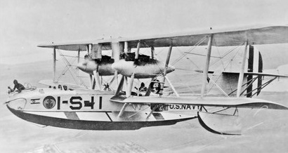
Immediately after World War I, the emphasis in naval aviation was on carrier operations, and patrol-plane development was carried out on a very limited budget. Building on the F-5-L flying boat-developed from the British-designed Felixstowe F.5 aircraft-the Naval Aircraft Factory (NAF) in Philadelphia produced an improved version of the twin-engine flying boat, which was redesignated PN-5 in 1922. 1 The designation PN-6 was used for two modified variants (originally F-6-L). In 1922 the F6L became Naval Aircraft Factory PN-6.
In mid 1980s, Research Council recommended that National Aerospace Laboratories should study the civil aviation requirements of India and recommended ways and means of establishing a viable civil aviation industry. It further recommended that NAL should carryout a formal techno economical feasibility study of a multi role Light Transport Aircraft (LTA – renamed SARAS in October 1993). The feasibility study (November 1989) showed that there was a significant demand for a 9–14 seat multi-role LTA in the country and estimated a market potential of about 250–350 aircraft in the next 10 years. NAL submitted the feasibility study report to RC in November 1990 and started its search for an industrial partner.
The project began in 1991 as a collaboration with Russia (Myasishchev had a similar project called the Duet), but financial trouble led the Russians to drop out early in the project, in 1997. The project almost came to a halt when it was hit by US-imposed sanctions in 1998, after India’s nuclear tests in Pokhran. It was recommenced in September 1999 upon receiving development approval from the Cabinet Committee on Economic Affairs in June 1999.
The project of ‘Saras’ was sanctioned on 24 September 1999 with initial schedule of its maiden flight by March 2001.
The original design target parameters included a maximum take-off weight of 6,100 kg and a maximum payload of 1,232 kg, a high cruise speed of over 600 km/h, an endurance of six hours, a maximum flight altitude of 12 km (cruise altitude 10.5 km), short take-off and landing distances of about 600 m, a maximum rate of climb of 12 m/s, a low cabin noise of 78 dB, a range of 600 km with 19 passengers, 1,200 km with 14 passengers and 2,000 km with eight passengers, a high ‘specific range’ of 2.5 km/kg and a low cost of operation of Rs. 5/km.
The Saras was designed to fly both day and night from semi-prepared airfields and grass runways. It was designed adhering to the FAR-25/23 standard regulations and can offer air taxi and commuter services.
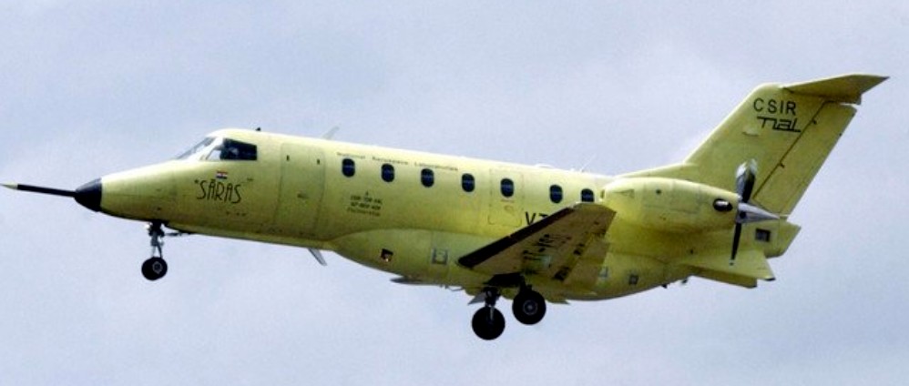
The first Saras (PT1) completed its maiden flight at the HAL airport in Bangalore on 29 May 2004 powered by two 850hp Pratt & Whitney PT6A-66 turboprop.
While the designed empty weight of the aircraft is around 4,125 kg, the first prototype weighed in around 5,118 kg. This was to be addressed by including composite wings and tail by the third prototype. It is being upgraded with 1,200hp Pratt & Whitney PT6A-67A engines to accommodate the overweight, new propellers and modern flight control and electrical systems.
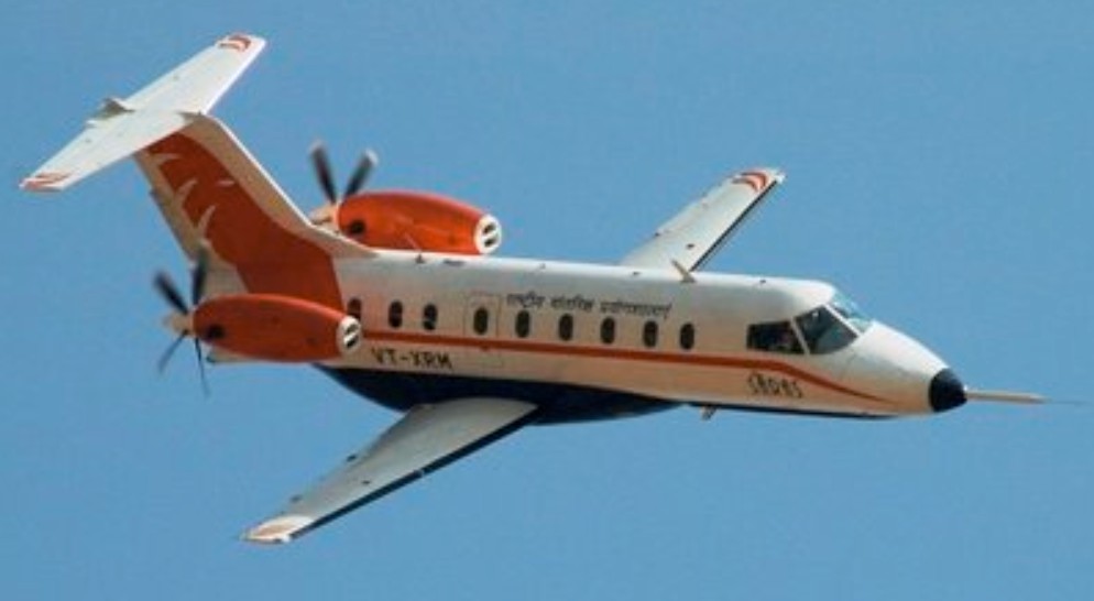
The airframe of Saras-PT2 was built with lighter composites to reduce its overall weight by about 400 kg from its first prototype, which was overweight by about 900 kg. The PT2 was powered by Pratt & Whitney PT6A-67A engine and completed maiden flight on 18 April 2007. A 2.65m diameter Hartzell five-bladed propeller will be fitted to each engine. The propellers can make 1,700rpm in pusher configuration.
The IAF has signed up with National Aerospace Laboratories, Bangalore for the purchase of 15 Saras aircraft.“NAL signed a memorandum of understanding with IAF to sell 15 Saras aircraft. The Kanpur unit of Hindustan Aeronautics Ltd will manufacture these planes,” The 14-seater twin-engine aircraft would be used for coastal surveillance as well as training young cadets on transport flying.
On 6 March 2009, 2 Indian Air Force test pilots, Wing Commander Praveen Kotekoppa and Wing Commander Dipesh Shah along with a Flight Test Engineer Squadron Leader Ilayaraja, were killed when the second prototype Saras aircraft crashed and caught fire in an open field near Bidadi, about 30 km from Bangalore. A court of inquiry found that wrong engine relight drills given to the pilots caused the crash.
Saras Engines: 2 × Pratt & Whitney Canada PT6A turboprop, 2150 shp (1634 kW) Wingspan: 14.70 m (48.23 ft) Length: 15.02 m (49.28 ft) Height: 5.20 m (17.06 ft) Useful load: 1,232 kg (2,710 lb) Max. takeoff weight: 7,100 kg (15,653 lb) Maximum speed: 550 km/h Cruise speed: 450km/h Range: 920 km Ferry range: 1,935km Service ceiling: 7,500 m (24,600 ft) Rate of climb: 10.5m/s Endurance: 4 hours 45 minutes Crew: 3 (Pilot, Co-Pilot, Flight Engineer) Capacity: 14 passengers
Robert T. Jones of Ames calculated that an aircraft’s wing made to pivot 4 degrees to the fuselage might halve the fuel consumption. Specifications bases, in particular geometric configuration were established by NASA based on one made by Boeing. In consultation with the Rutan Aircraft Factory, Ames and Dryden built the AD-1 oblique wing aircraft in 1977, a twin jet composite aircraft with direct controls and a top speed of 175kts (324kph). Set perpendicular to the fuselage for takeoff and landing, the oblique wing could be made to rotate up to 60 degrees for higher speed flight and between 1979 and 1982, demonstrated the feasibility of such a concept, performing three landings with the wings pivoted at 45 degrees.
The test aircraft’s 32 foot wing can be pivoted 60 degrees during cruise, to reduce drag while still allowing high airspeeds. In the conventional position, the wing should provide ample lift and stability for takeoffs, landings and low speed manoeuvres. Designated the AD 1, the test aircraft is 40 feet long, has a gross weight of 2,000 pounds and is powered by two 220 pound thrust turbojets. The structure was made entirely of fiberglass.
The aircraft was delivered by Aimes at Dryden Flight Research Center at Edwards Air Force Base in March 1979. The first flight was performed by test pilot NASA Thomas C. McMurtry December 21, 1979. Thomas flew only the 79 flights until 7 August 1982.
Although the oblique wing is still considered by some as a viable concept for large transport, unpleasant flight characteristics of the AD-1 at certain angles discouraged designers to adopt this configuration.
Engines: 2 x Microturbo TRS-18, 220 lb / 100 kg Wing span: 9.85 m / 34 ft 2 in Length: 11.82 m Wing area: 8.60 m² Aspect ratio: 11.2 Thickness/chord: 12% Loaded weight: 809 kg Empty weight: 535 kg Max speed: 220 knts Min speed: 74 knts Seats: 1
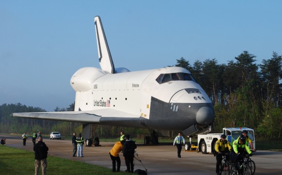
There had long been the desire to have a reusable vehicle that could be launched into Earth orbit, have the ability to manoeuvre in space, re enter Earth’s atmosphere and land conventionally on an airfield. The first step in this direction was made with lifting body research aircraft which, in turn, led to design of the Space Shuttle Orbiter, for which Rockwell International became prime contractor in July 1972.
A large vehicle with a thick section wing of double delta planform, the SSO has a fuselage which conforms to lifting body outlines. Mounted in the rear fuselage are three Rocketdyne SSME rocket engines, each developing 417,300 lb (189287 kg) thrust for launch, at which time the SSO has mounted beneath it a large external fuel tank for the SSME rocket engines, and at each side of the tank a solid propellant rocket booster. The whole assembly is launched with the main engines and the boosters firing; after burn¬out the boosters are jettisoned and recovered by parachute, the main engines then being fed from the external fuel tank, which is jettisoned just before entry into orbit. Having completed its orbital mission, during which the SSO is controlled by orbit manoeuvring and reaction control engines, a de orbiting manoeuvre is initiated and, at a high angle of attack, the SSO re enters Earth’s atmosphere to make an unpowered but otherwise conventional aircraft type landing.
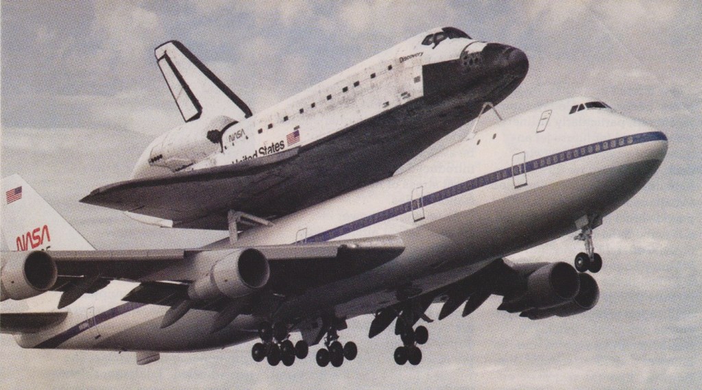
It was not until 13 August 1977 that the Enterprise and its crew were launched in free flight from the SCA at a height of 22,800 ft (6950 m), to make a gliding and unpowered flight to a conventional landing at Edwards AFB, California.
Boeing 747 123 Shuttle Carrier Aircraft (SCA) (NASA 905)
Almost four years later, on 12 April 1981, the spacecraft OV 102 Columbia, crewed by astronauts John Young and Robert Crippen, lifted off from Cape Canaveral on the first orbital mission. It then completed 37 orbits of the earth in 54 hours and on 14 April made a near perfect unpowered 200 mph (322 km/h) landing on Runway 23 at Rogers Dry Lake, Edwards AFB, California. The first ever “soft” return from space in a re-usable craft that is part spaceship and part aeroplane.
The Columbia was subsequently flown back to Cape Canaveral on the back of its Boeing 747 mother-plane for full examination and preparation for the next mission.
As Shenyang began developing MiG-19s locally under the J-6 name in 1958, the PLAAF requested the development of the design into a dedicated attack aircraft. Shenyang assigned the same project manager as the one in charge of the J-12 program. The aircraft was designated Qiangjiji-5 (Q-5) which stands for Attack aircraft 5. A long list of changes was made to the MiG-19 design, making the new aircraft virtually unrecognizable. The intakes were moved to the fuselage sides to make space for a radar, while the aircraft was lengthened and area ruled to make space for an internal weapons bay and reduce transonic drag, respectively. The wing root 30mm cannon of the J-6 were replaced with 23mm cannon, but payload was doubled to 2,000kg, and the number of hardpoints was increased from four to six. Meanwhile, larger, less swept wings were added. Although it was designed by Shenyang, further development and production were assigned to Nanchang. The prototype was completed in 1960, but due to the political climate at the time, was cancelled before it took flight in 1961.
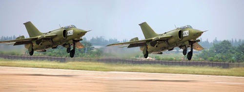
The prototype program was kept alive by small team and resumed officially 1963, when the PLAAF revived the project and moved it to Nanchang. First flight took place on 4 June 1965, featuring an area ruled fuselage for minimum transonic drag, cockpit armour protection, a “solid” nose and a weapon bay (for early test and production aircraft, but omitted from improved production versions). The Q-5 (particularly its wing) is based on the Mikoyan-Gurevich MiG-19, already built in the People’s Republic under the designation Shenyang J-6. Slightly longer than its ancestor, the Q-5 differs considerably in profile by reasons of a ‘solid’ nose and cheek air inlets made necessary by transfer of some avionics from the centre fuselage to make way for an internal weapons bay (now used for additional fuel), although the MiG’s four wing strongpoints and root-mounted cannon are retained for close support work. Over¬all length was increased, and wing span was extended to compensate. An internal weapons bay was incorporated, but this is now used to house additional fuel, increasing internal fuel capacity by 70 per cent. External stores are carried on four underwing and four under-fuselage stations. Powered by the same Soviet-designed, Chinese-built engines as the J-6, this variant has a taller fin and a narrower centre fuselage. A camera mounted on starboard side of the nose is for gunnnery recording only.
Performance was found to be slightly worse than the J-6 at high altitude, but it was just as fast at low altitudes. Further modifications were found necessary, leading to flight test of two much modified prototypes from October 1969. Known in the West as the Nanchang A-5 ‘Fantan-A’ and to the People’s Liberation Army Air Force as the Qiangjiji-5 (Attack Aircraft Type 5), the Q-5 was revealed in limited detail only during 1980.
Series production was approved at the end of 1969, with deliveries beginning 1970. A total of approximately 1000 aircraft were built, of which nearly 600 were the improved Q-5IA variant. A small number, perhaps a few dozen, of the Q-5IAs were modified to carry nuclear weapons. The nuclear capable Q-5A first flew on 1st August 1970. The Q-5A added two more hardpoints. On 7th January 1972, a Q-5A dropped a 20 kT nuclear bomb on Lop Nor nuclear test site in northwest China.
A long-range variant emerged, replacing the interal bay with a fuel tank, and the late production Q-5D received advanced HUDs, laser designators, and FLIR. In the late 1980s, there were plans to upgrade the Q-5 fleet with the avionics of the AMX International AMX, but these plans fell through after sanctions over the heavy-handed response to the 1989 Tiananmen Square protests.
Exported from 1983 as the A-5, North Korea was the first export customer for the aircraft, buying 40 Q-5As.
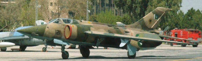
Peak production levels were attained in the early 1970s, and by 1978 production had almost come to an end. Export orders from North Korea, Burma and Pakistan, together with additional local requirements, caused production to be increased in the early 1980s. 40 or more were delivered to Pakistan in 1982-3. Pakistan required an eventual total of some 150 of this type.
1984 production models at Nanchang were the Q-5-III for Chinese use, and the A-5C for export. The A-5C (Q-5III) is the improved version of the Q-5I variant. It was flight tested in late 1980 and certified for production on 20 October 1981 and was exported in 1983 to Bangladesh (20) and Pakistan (52).
In 1988 the A-5M version first flew with a ranging radar, and simultaneously the Q-5K Kong Yun entered testing with a French avionics package.
A small number of aircraft were modified to carry nuclear weapons designated Q-5A. The Q-5B was equipped with a Doppler radar in a reshaped nose and was capable of carrying two torpedoes for maritime strike missions. Q-5I was the first improvement of the Q-5 design. The internal bomb bay was deleted in favour of more internal fuel storage to extend the aircraft’s range. The landing gear was strengthened and two extra hardpoints were fitted. Some of the Q-5I aircraft for the Navy were fitted with Doppler radar making it capable of using the C-801 Anti-Ship Missile.
The Q-5IA is an upgraded Q-5I featuring two extra underwing hardpoints and a new gun/bomb-sighting system. Later RWR was added which resulted in the Q-5II. The Q-5IA was further enhanced and offered for export designated A-5C (Q-5III). The A-5C incorporated many modifications including upgraded avionics and AIM-9 Sidewinder AAM capability.
Upgrade programmes involving Western avionics such as laser rangefinder, INS, and HUD systems from Thomson-CSF started in 1986 with France (Q-5K Kong Yun based on the Q-5II) and Italy (A-5M), but Kong Yun programme terminated in 1990. The all-weather Q-5M (A-5M) incorporated the nav/attack system from the AMX aircraft, and made its first flight on 30 August 1988 and 24 aircraft were ordered by Myanmar. Later that year the A-5M prototype crashed and somewhere in the second half of the 1990s the program was ultimately stopped. Some sources say that Myanmar bought 24 A-5Cs from China instead.
In late 2003, Sudan was reported to have acquired 15-20 A-5Cs from China, believed to be financed by Iran. Reports indicated that Sudanese pilots were trained in China, Iran and locally in Sudan. Pakistan Air Force instructors were said to be involved in the training of Sudanese aircrew, particularly at Dezful-Ardestani Air Base in southern Iran. In January 2007, two Sudanese Air Force A-5Cs (serials 402 and 403) deployed to Nyala Airport, southern Darfur, with at least one more (410) being deployed later. Sudan failed to submit a prior request to the UN for their deployment, as required under UN Security Council resolution 1591.
The two-seat JQ-5J version was developed by Hongdu Aviation Industry Group (HAIG). It was first revealed to the public in the form of a model at the Zhuhai Air Show in December 2004. In addition to the redesigned front fuselage the aircraft features a larger vertical tail. The first prototype JQ-5J made its maiden flight on 25 February 2005.
Q-5 Powerplant: two 3250-kg (7,165-1b) thrust Shenyang Wopen-6 (Tumansky R-913F-811) afterburning turbojets Wing span: 9. 70 m (31 ft 10 in) Length 16.73 m (54 ft 10.5 in) Height 4.51 m (14 ft 9.5 in) Empty weight: 6494 kg (14,317 lb) Maximum take-off weight: 12000 kg (26,455 lb) Maximum speed 11000 m (36,090 ft): 1190 km/h (739 mph) or Mach 1.12 Maximum speed sea level: 1210 km/h (752 mph) Service ceiling 16000 m (52,495 ft) Combat radius lo-lo-lo max load: 400 km (249 miles) Combat radius hi-lo-hi: 600 km (373 miles) Armament: two 23-mm Type 23-2 cannon (with 100 rpg) in wing roots Hard points: four wing and four fuselage pylons carrying (normally) 1000 kg (2,205 lb) or (maximum) 2000 kg (4,409 lb) of ordnance
Q-5A
Q-5 Fantan A Engine: 2 x Wopen WP-6. Installed thrust (dry / reheat): 51 / 64 kN Span: 9.7 m Length: 15.7 m Wing area: 28 sq.m Empty wt: 6500 kg MTOW: 12,000 kg Warload: 2000 kg Max speed: 1.1+ Mach Ceiling: 16,000 m T/O run: 1250 m Ldg run: 1050 m Combat radius lo-lo-lo: 400 km Fuel internal: 3700 lt Air refuel: No Armament: 2 x 23 mm Hard points: 8
Q-5B
Q-5I
Q-5IA
Q-5II
Q-5III / A-5C Powerplant: two 31.87 kN (7,165 lb st) Shenyang Wopen-6 (WP6) afterburning turbojets Length 16.25m (53 ft 4 in) Height 4.52m (14 ft 10 in) Wing span 9.70m (31 ft 10 in) Empty weight: 6494 kg (14,317 lb) Max Take-Off Weight: 12000 kg (26,455 lb) Max level speed at 11.000m (36,000 ft) Mach 1.1 or 1190 km/h (740 mph) Service ceiling 15,850 m (52,000 ft) Armament: two Type 23-2K 23mm cannons with 100 rounds per gun; up to 2000 kg (4,410 lb) of ordnance
Design work on the YS-11 began in 1957 when the Japanese Ministry of International Trade and Industry (MJTI) urged six of the country’s leading aviation companies to join forces in the development of what was to become Japan’s first postwar airliner. The ensuing joint design bureau became known as TADA (Transport Aircraft Development Association or Yusoki Sekkei Kekyu Kyokai). What finally came off the drawing boards was a conventional design, tailored for the Japanese domestic market. In 1959 TADA was replaced by NAMC (Nihon Aeroplane Manufacturing Company) to provide manufacturing and marketing capability. Among the participating companies, construction responsibilities were divided as follows: Fuji – tail unit; Japan Aircraft – control surfaces; Kawasaki – wings; Shin Meiwa- aft fuselage; Showa Aircraft – composite structures; and Mitsubishi – forward fuselage and final assembly.
Two prototypes were built by NAMC, each powered by two 3,060 h.p. Rolls-Royce Dart RDa.10/1MkP542 engines, plus two further airframes for static testing. Fifty-four YS-11s were to be built between 1963 and 1966, according to plans, for All-Nippon Airways (25), Japan Air Lines (about 10), the Japanese Defence Agency (10), the Maritime Safety Agency (2 for ASR) and the Meteorological Agency (four for weather observation).
The first flight came on August 30, 1962, when the YS-11 first took to the skies. Japan Domestic Airlines placed the type into service on April 1, 1965. A higher gross weight version, the YS-11A, became available in 1967. Not surprisingly, Japanese airlines were the largest customers, although Piedmont Airlines took delivery of 21 aircraft. Other customers included Hawaiian Airlines, Cruzeiro do Sul, VASP, and Olympic Airways. Throughout its production life, the YS-11 was dependent on state subsidies. In 1971 the Japanese government announced that it would no longer provide financial backing and production ended two years later, with a total of 182 aircraft completed. Although from an economic point of view the YS-11 was a Y38 billion disaster for Japanese taxpayers, the airplane itself proved to be a solid and reliable design. Over the years, many YS-11s were passed on to smaller operators all over the world. Among these were a number of US-based com¬panies, such as Mid Pacific Air, Provincetown-Boston Airline, Reeve Aleutian Airways, Simmons Airlines, Pinehurst Airlines, and Airborne Express.
112 of the YS 11 were in service in 1981, the largest operators being TDA with 42 and ANA with 34. The fleet has totalled more than three million hours.
Engines: two 3,060 h.p. Rolls-Royce Dart RDa.10/1MkP542 Span: 105 ft Length: 86 ft 3 in Height: 30 ft Gross weight: 50,265 lb Empty weight (equipped): 31,970 lb Max cruising speed at 20,000ft: 296 mph Econ cruising speed at 20,000ft: 288 mph Max rate of climb at SL: l,520 ft/min Service ceiling: 27,500 ft TO field length (SR422B): 2,900 ft; Landing field length (SK422B): 3,790 ft Range max fuel/ 5,4001b load, res 230-mile & 45min: 1,485 miles Range with max payload, same res: 380 miles
YS-11A-500 Engines: 2 x RR Dart Length: 26.3m (86.3ft) Wing span: 32m (105ft) MTOW: 25,000kg (55,115kg) Max payload: 5,900kg (13,000lb) Economical cruise: 245kt ROC: 800fpm at l40kt Takeoff dist: 1,200m (3,940ft) Landing dist: 1,000m (3,280ft) Range (max fuel): 1,735nm Range (max load): 600nm
Japan’s interest in jets increased in September 1944, when the Japanese air Attache in Berlin sent a large number of detailed reports on the German Me262 program. The Japanese naval staff instructed Nakajima to develop a single seat attack bomber based on the Me 262, capable of a speed of 690 km/h (430 mph) and able to carry a small bombload.
Design started in Septem¬ber 1944 under the direction of Kazuo Ohno and Kenichi Matsumur, and the resulting aircraft resembled the Ger¬man design although somewhat smal¬ler owing to the very low power avail¬able from the early Japanese jet en¬gines. The Kikka first design studies envisaged the use of 440 lb. thrust TSU-11 units which were based on the Campini principles and employed the Hitachi Hatsukaze (Fresh wind) piston engine to drive a ducted fan compressor. However, at an early design stage the Tsu-11 was dropped in favour of the Ne-10 (TR-10) centrifugal-flow turbojet, and the 340 kg (750¬lb) thrust NE-12 (TR-12), which added a four-stage axial compressor to the front of the Ne-10. The first mock-up of the Kikka was inspected by Naval Officials on January 28, 1945, but estimated performance with the NE-12 turbo jet was uninspiring, and it was decided to make a further power plant change, supplanting the NE-12 with two 475 kg (1,047 1b) thrust powerful NE-20.
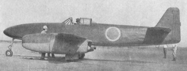
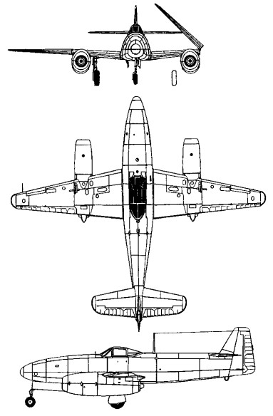
The Kikke was a single-seat twin-jet attack bomber, of all-metal construction with fabric-covered tail surfaces.
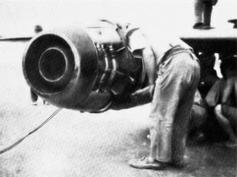
Ishikawajima NE-20 fitted on Kikka No1
These also proved inadequate and for the first flight Ne 20 axial flow turbojets were fitted; however, it was still necessary to employ an auxiliary rocket for assisted take off.
The prototype commenced ground tests at the Nakajima factory on 20th may 1945, and on 25th June the first Kikka was completed. The following month it was dismantled and delivered to Kisarazu Naval Air base where it was re-assembled and prepared for flight testing. Ground tests continued on this airfield until 13th July.
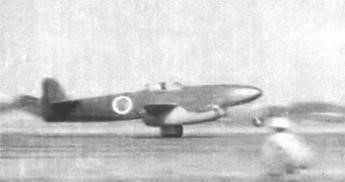
On the 7th August 1945, Lieutenant Commander Susumu Takaoka made the first flight, with a duration of 11 minutes at Kisarazu Naval Air Base. His take-off run of 2,380 ft. took 25 seconds at an all-up weight of 6,945 lb. Wind speed was 23 ft.per second. He landed in 3,280 ft.
A ceremonial official “initial” test flight was made on 11th August, four days later. For this flight, rocket assisted take off (RATO) units were fitted to the aircraft. Because their alignment had been miscalculated, the acceleration was so heavy that the nose of the aircraft came up, the tail went down and skidded along the runway. Tanaoka abandoned the take off and the aircraft was damaged when it ran off the end of the runway. Before it could be repaired Japan had surrendered and the war was over.
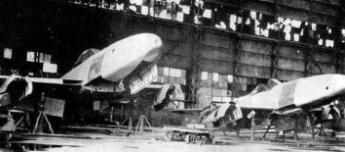
A second prototype was then nearing completion and manufacture of between 18 and 25 further aircraft had started. Some of these were two-seat trainers. On 15 August, the entire programme was abandoned. Production, which included versions for training, reconnaissance and air combat, had also been planned.
Kikka (1st prototype) Powerplant: two Ishikawajima Ne 20 axial flow turbojets, 475 kg (1,047 1b) thrust Wing span 10.00 m (32 ft 10 in) Length 8.125 m (26 ft 8 in) Height 2.95 m (9 ft 8 in) Wing area 13.2 sq.m (142.08 sq.ft) Empty weight 2300 kg (5,071 lb) Maximum take off weight 4080 kg (8,995 lb) Wing loading: 54.3 lb./sq. ft. Power loading: 3.7 lb./lb. s. t. Max speed sea level (est): 387mph Max speed 697 km/h (433 mph) at 10000 m (32,810 ft) Climb to 10000 m (32,810 ft) in 26 min Service ceiling 12000 m (39,370 ft) Range 940 km (586 miles) Armament: one 800 kg (1,764 lb) bomb Crew: 1