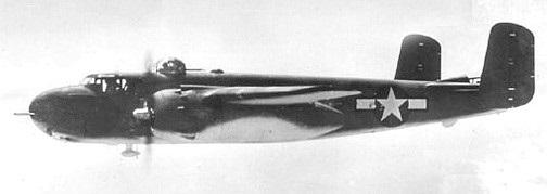
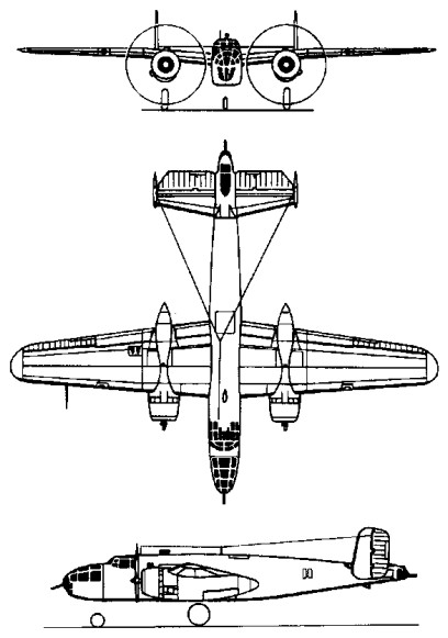
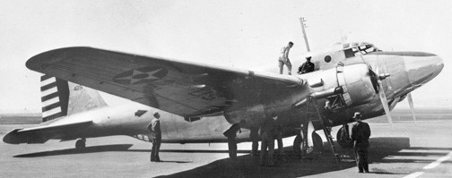
Envisaged originally as a high-altitude version of the B-25 Mitchell, the North American NA-63 (XB-28) emerged finally as an almost entirely different aircraft. With single vertical tail surfaces and a circular-section fuselage with a pressure cabin for the five-man crew, the XB-28 was powered by two 1491kW Pratt & Whitney R-2800 radials and bomb bay capacity was 1814kg and -28A with R-2800-27. Dorsal, ventral and tail turrets, each containing two 12.7mm machine-guns, were remotely controlled from the cockpit; three similar forward-firing weapons were also fitted.
North American XB-28 40-3056
Of three prototypes ordered in February 1940, the first flew in April 1942 (40-3056), the second (40-3058), with a reconnaissance camera installation, crashed during the test programme and the third was cancelled. Although the XB-28 achieved a maximum speed of 599km/h at 7620m and could carry a 272kg bomb load for 3283km, production orders were not placed when no particular need for such a plane was found. A third prototype was unbuilt.
XB-28 / NA-63 Engines: two Pratt & Whitney R-2800-11, 11491kW / 2000 hp Wingspan: 22.12 m / 72 ft 7 in Length: 17.20 m / 56 ft 5 in Wing area: 62.80 sq.m / 675.97 sq ft Max take-off weight: 16226 kg / 35772 lb Empty weight: 11611 kg / 25598 lb Useful load: 10,165 lb Max speed: 372 mph Cruise speed: 411 km/h / 255 mph Stall: 86 mph Ceiling: 34,600 ft Range: 3284 km / 2041 miles
XB-28A / NA-67 Engines: two Pratt & Whitney R-2800-27, 11491kW / 2000 hp Wingspan: 22.12 m / 72 ft 7 in Length: 17.20 m / 56 ft 5 in Wing area: 62.80 sq.m / 675.97 sq ft
Built as a private venture, the NA-40-1 prototype flew in January 1939. The design was extensively modified as NA-62 after Wright Field testing and 1700hp R-2600s installed.
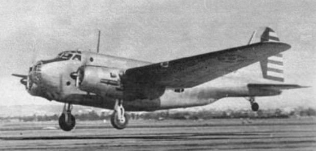
Ordered into production in 19 August 1939 it took just fifty-three weeks after receiving the initial contract before the first prototype took to the air. The initial order for 24 as B-25: 40-2165 to 40-2188. The prototype of the B-25 was flown for the first time on August 1940. The first of these 184 B-25 Mitchell entered service in 1941.
North American B-25 Straight-wing, narrow tails 40-2165
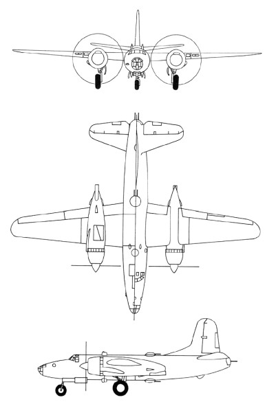
It and the first few B-25s off the production line had wings with a constant dihedral from the fuselage to the tips. Only after the 10th one were the wings redesigned with the characteristic gull configuration. Its armament included four .30-caliber machine guns, one in the nose and three amidships, and a single .50-caliber gun in the tail. The usual bomb load was 2,000 pounds with a maximum overload of 3,600 pounds. Large scale production began immediately and early models were in service by the time America entered the war in December 1941.
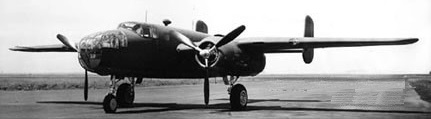
North American B-25A
The B-25A was fitted with self-sealing fuel tanks and armor for the pilot. The B replaced the midship and tailguns with electrically operated turrets. Each turret had two .50-caliber machine guns. The lower turret was remote-controlled. 120 of the 1941 B-25B (NA-62B) were built; 40-2229 to 40-2242, and 40-2244 to 40-2348, of which 23 to went to the RAF/RAAF.
North American B-25B 40-2321
The C and D were provided with automatic flight control equipment.
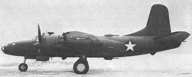
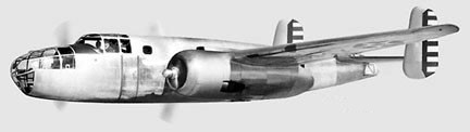
North American B-25C 41-12800
The B-25C was the first version of the Mitchell to be mass-produced. Following the completion of the initial B-25, B-25A, and B-25B contracts, a number of contracts were awarded to North American for 1625 B-25Cs to be built at its Inglewood factory. At the same time, an additional contract was issued for 2290 essentially identical B-25Ds, to be built at a new North American plant in Kansas City, Kansas.
The first B-25C contract was approved on September 24, 1940 for 863 aircraft under the company designation NA-82. On June 24, 1941, the Netherlands government ordered an additional 162 aircraft under the designation NA-90 which were later built as the B-25C-5. Lend-Lease funds financed contracts signed on January 23, 1942 for 150 NA-94 (B-25C-10) for Britain and 150 NA-93 (B-25C-15) for China. However, these allotments were not followed in the delivery of actual aircraft.
The B-25C was outwardly almost identical to the B-25B. It introduced the R-2600-13 Double Cyclone engine with Holley 1685HA carburetors in place of the earlier Bendix Stromberg PD-13E-2 units. The Bendix carburetors were favored because of their easier maintenance, but they required more careful anti-icing procedures. De-icer and anti-icing systems were added, and a Stewart-Warner cabin heater was added in the left wing. A 24-volt electrical system was also added.
The armament of the B-25C was the same as that of the B-25B, namely a single 0.30-inch machine gun in the nose, two 0.50-inch machine guns in the dorsal turret, and two 0.50-inch machine guns in a retractable ventral turret. The ventral turret was often removed in the field.
The B-25C introduced a new type of tail skid underneath the extreme rear fuselage, a solid unit which replaced the spring-loaded tail skid of earlier versions. This type of tail skid was retained throughout the Mitchell production run.
On the earlier B-25s, the exhaust pipe coming out of the back of the engines extended all the way to a position underneath the forward leading edge of the wing. On the B-25C, the exhaust pipes were considerably shortened, and terminated immediately behind the engines.
The fuel was carried in four tanks in the inner wing panels, with a total capacity of 670 US gallons. In addition, a 515-gallon tank could be installed in the bomb bay for ferrying purposes, bringing total fuel capacity to 1255 US gallons.
Beginning with B-25C serial number 41-12817, a small transparent scanning blister was installed above the navigator’s station. At this time, the turrets were changed to Bendix Amplidyne type, and a carbureter air filter was added. Changes were made so that an additional 304 US gallons of fuel could be carried in auxiliary cells in the outer wing panels, for a total of 974 US gallons.
The B-25C-1 production block introduced under-wing bomb racks which could accommodate six to eight 100- to 325-pound bombs. In addition, provisions were made for a rack underneath the fuselage capable of carrying a short 22.4-inch torpedo weighing 2000 pounds. If the torpedo was carried, no bombs could be, although a bomb bay fuel tank could be used. The Mitchell was employed only in limited numbers as a torpedo plane against Japanese shipping. However, extensive use was made of the external wing racks, which could carry six to eight bombs of 100-325 pounds in weight.
Beginning with the B-25C-5 production block, the 0.30-inch nose gun was removed and replaced by a flexible 0.50-inch machine gun in the extreme nose and a fixed 0.50-inch machine mounted on the starboard side of the nose and firing through a hole cut into the side of the Plexiglas glazing. At the same time, better winterization provision were made.
The B-25C-5 production block also introduced a new type of engine exhaust. The B-25B and earlier C versions had a problem with bright spurts of flame being emitted from the exhaust, a dead giveaway during night operations. This problem was so bad that the Mitchell had to be restricted from night operations where enemy aircraft could be expected. In these earlier versions, the exhaust from each cylinder head was gathered by a collector ring, which directed the exhaust to the outside via a single pipe on the side of the nacelle away from the fuselage. Several different exhaust modifications were tried out in an attempt to alleviate this problem. The most effective arrangement was found to be a the replacement of the single exhaust pipe by a set of “finger”-type flame dampening exhaust collectors which ported the exhaust through groups of small rectangular outlets that stuck out underneath the trailing edge of the cowl flaps. These “finger”-type flame dampeners were installed on the production line beginning with the B-25C-5 production block. These were fairly effective flame quenchers, but they suffered considerable cracking and few B-25Cs reached combat zones without the replacement of these finger exhausts by full collector rings or by the later Clayton S-shaped stacks that were introduced on the -15 production block.
The B-25C-10 production block introduced an AM remote reading compass, provisions for additional cabin heating, and an improved scanning lens for the sig.
Beginning with the B-25C-15 production block, the exhaust collector ring was replaced with Clayton “S”-shaped flame dampening stacks attached to each individual cylinder. Cutouts and fairings were added to the cowling panels where each of the stacks protruded, creating a rather cluttered cowling shape. These protrusions introduced a slight speed penalty, but this was considered an acceptable tradeoff in view of the better flame dampening that was achieved. This feature was provided on all subsequent Mitchells. However, the new exhaust system was not all that popular with Mitchell crews, since it resulted in an increase in cockpit noise as compared to the old arrangement in which collector rings ported the exhaust to the outboard side of the nacelles.
At the same time, emergency hydraulic landing gear lowering devices were provided. The fuel capacity consisted of four tanks in the inner wing panels, with a total capacity of 670 US gallons. In addition, a 515-gallon tank could be installed in the bomb bay for ferrying purposes, bringing total fuel capacity to 1255 US gallons. Later versions had additional auxiliary fuel tanks in the outer wing panels. Later versions could also have 125-gallon tanks fitted in side waist positions, a 215-gallon self-sealing fuel tank installed in the bomb bay, and provisions could be made for a droppable 335-gallon metal bomb-bay fuel tank. Armament: Two 0.50-inch machine guns in dorsal turret. Two 0.50-inch machine guns in retractable ventral turret. One 0.30-inch machine gun in flexible mount in the nose. Starting with B-25C-5 the 0.30-inch nose gun was removed and replaced by a flexible 0.50-inch machine gun in the extreme nose and a fixed 0.50-inch machine mounted on the starboard side of the nose and firing through a hole cut into the side of the Plexiglas glazing. Normal bomb load was 3000 pounds but could be increased on the B-25C-1-NA with external underwing racks to a maximum of 5200 pounds.
Deliveries on a new contract (NA-96) began in February 1943 with the similar B-25C-20.
Beginning with production block B-25C-25, a “clear-vision” windshield was installed. Provisions were made for the fitting of additional fuel tanks for ferrying purposes. 125 gallons of fuel could be carried in side-mounted tanks in the waist position. A 215-gallon self-sealing fuel tank could be installed in the bomb bay, and provisions for a droppable 335-gallon metal bomb-bay fuel tank were made on every second airplane. B-25C serial number 43-32732 was fitted with a special bomb bay rack to carry an airborne flame thrower. The results of tests with this unusual feature are unknown.
The first B-25C was accepted in December of 1941, with the 1619th and last one being delivered in May of 1943. The B-25C; 42-32233 to 42-32280, 42-32282 to 42-32383, 42-32389 to 42-32532, 42-53332 to 42-53493, and 42-64502 to 42-64901, were built as NA-82, NA-90, NA-93, and NA-94. The NA-93 and -94 were exports to China and RAF, respectively.
The 1942 XB-25E and -25F were fitted with experimental deicing equipment. One each were conversions from -25C with new s/n; 43-32281 and 43-32282.
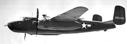
The G was the first model to carry a 75mm Army M-4 cannon in the nose. One conversion from a B-25C with new s/n, 43-32384, was completed in 1942 as the XB-25G.
North American B-25G Cannon installation
The B-25G (NA-96) of 1942 was a four-crew production model with the M-4 cannon. 405 were built; 42-64902/65201, and -64802/65201.
North American B-25G 42-65128
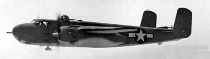
The 1943 B-25H (NA-98) increased its armament to four .50-caliber guns in an armored nose and two pairs of .50-caliber guns on each side of the fuselage. It was the precision bomber version of the H; the crew increased to six to include a bombardier.
North American B-25H
1,000 B-25H were built: 42-4105/5104.
The B-25J, built at the Kansas plant, was the most widely produced version, 4318 being produced 1943-45.
More than 700 B 25s were acquired by the U.S. Navy and Marines, as the PBJ. USN/USCG transfers of USAAF B-25 for use in mine-laying, harassing night raids, and bombing and torpedoing ships in the Southwest Pacific theatre.
The US Marine Corp operated B-25s as the PBJ-1C (1943 50 ex-B-25Cs; 34998-35047), PBJ-1D (1943 152 ex-B-25Ds; 35048-35096, 35098-35193, 35196-35202), PBJ-1G (1 ex-B-25G; 42-65031/35097), PBJ-1H (248 ex-B-25Hs; 35250-35297, 88872-89071), and PBJ-1J models (255 ex-B-25Js; 35194-35195, 35203/35249, 35798-35920, 38980-39012, 64943-64992).
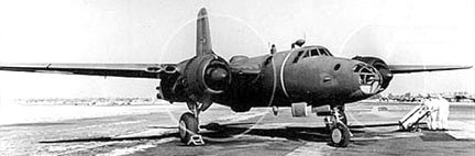
North American PBJ-1H
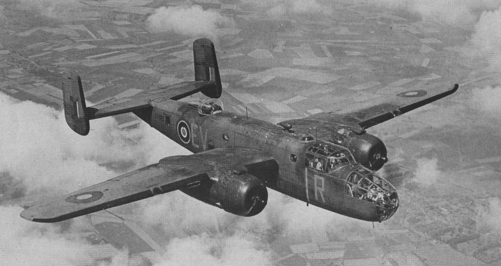
The Royal Air Force received about 800, and the airplane was flown more than a dozen other countries. Top speed only reached about 270 mph but the Mitchell’s 1,350 mile range made it very useful.
The Americans did not use Mitchells operationally from the United Kingdom but based them with the 12th United States Army Air Force in the Mediterranean. However the British, Dutch and Russians received large numbers.
Mitchell II
Training aircraft were the AT-25, later designated the TB-25.
All B-25 models were powered by Wright R-2600 Cyclone 14 engine. More than 12000 aircraft built.
In April 1942 sixteen Mitchells, operating from the American aircraft carrier USS Hornet, made one of the most daring bomber raids in the Second World War, on Tokyo.
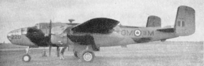
In 1955 large numbers of these wartime medium bombers were still used by the R.C.A.F. for a variety of duties. The target towing version shown here is powered by two 1,700 h.p. Wright R2600-13 engines.
B-25D
About 100 B-25Js, with glazed noses, are used for all weather crew training and guided weapon development. Other B-25Ds and Js were used by Reserve squadrons. TB-25s were in service with the U.S.A.F.
The Mitchell was used in all theatres and a total of 9816 were built, essentially unaltered in airframe and engines, but revised in armament, armour and fuel. There were 1619 B-25C built, and 1000 B-25J. A total of 9,816 were delivered to USAAF, and about 2,000 more exported to Allied air services. The USN version was the PBJ. The last, a TB-25, was finally retired from USAAF duty in Jan 1959.
B-25A / NA-62A Max speed: 315 mph Cruise speed: 262 mph Stall: 90 mph Range: 1350 mi Ceiling: 27,000 ft
B-25B Dorsal & ventral turrets
B-25C / PBJ-1C Engines: Two Wright R-2600-13 Double Cyclone, 1700 hp takeoff, 1500 hp at 2400 rpm. Wingspan: 67 ft 67.7 in Length: 53 ft 0 in Height: 15 ft 9 in Wing area: 610 sq.ft Empty weight: 20,300 lb Maximum weight: 34,000 lb Maximum speed: 284 mph at 15,000 ft. Cruising speed: 233 mph at 15,000 ft. Initial climb rate: 1100 fpm Time to 15,000 ft: 16.5 min Service ceiling: 24,000 ft Range: 1500 miles with 3000 lb bombs. Internal fuel capacity: 670 US gal Ferry fuel capacity: 1255 US gal Opt fuel later mods: 800 US gal Armament B-25C: 4 x 0.50-inch machine guns, 1 x 0.30-inch machine gun Armament B-25C-5: 6 x 0.50-inch machine guns Normal bomb load: 3000 lb Underwing bomb load B-25C-1-NA: 2200 lb Max bomb load B-25C-1-NA: 5200 lb
B-25D Mitchell / PBJ-1D Ventral bomb racks Engines: two 1,700 h.p. Wright R2600-13 Span: 67 ft. 7 in Max Weight: 33,500 lb Max Speed: 303 m.p.h.
B-25G / PBJ-1G / NA-96 Length: 51’0″ Max speed: 281 mph Cruise speed: 248 mph Stall: 105 mph Range: 1560 mi Ceiling: 24,300 ft Armament: 75 mm M-4 cannon Crew: 4
B-25H / PBJ-1H / NA-98 Improved B-25G Engines: Wright R-2600-13 Cyclone, 1700 hp / 1268 kW Wingspan: 67 ft 7 in / 20.60 m Length: 51 ft 0 in / 13.34 m Height: 15 ft 9 in / 4.80 m Wing area: 610,0 sq.ft / 56.67 sq.m Empty weight: 19,975 lb / 9061 kg MTOW: 36,047 lb / 16,351 kg Max speed: 275 mph / 442 kph at 13,000 ft / 3960 m Cruise speed: 230 mph Stall: 105 mph Climb to 15,000 ft / 4570 m: 19 min 0 sec Service ceiling: 23,800 ft / 7255 m Range: 2700 mi / 4344 km Armament: 1 x 75mm T-13E1 cannon, 12 x .50 in mg Bomb load: 3200 lb / 1452 kg or 1 x 2000 lb / 907 kg torpedo Seats: 5
B-25J / PBJ-1J Improved B-25H initially with B-25D glazed nose, later solid 8 gun nose Engines: 2 x Wright R-2600-92 Cyclone, 1268kW / 1700 hp Wingspan: 20.6 m / 67 ft 7 in Length: 16.13 m / 52 ft 11 in Height: 4.98 m / 16 ft 4 in Wing area: 56.67 sq.m / 609.99 sq ft Max take-off weight: 15876 kg / 35001 lb Empty weight: 8836 kg / 19480 lb Fuel capacity: 811 gal Max. speed: 237 kts / 438 km/h / 272 mph at 13,000 ft Cruising speed: 200 kts / 370 km/h Ceiling: 7375 m / 24200 ft Cruising altitude: 12992 ft / 3960 m Wing load: 57.4 lb/sq.ft / 280.0 kg/sq.m Range: 2173 km / 1350 miles with 3000 lb bombload Armament: 12 x 12.7mm / .50 machine-guns, 1300-1800kg of bombs Crew: 5
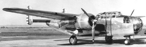
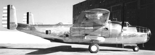
A twin-engined Attack Bomber was produced in 1939 and was available for export as the NA-40 series. A single prototype was built.
The NA-40-1 NX14221 was first flown in January 1939 by Paul Balfour, powered by two 1100hp P&W R-1830. It was re-powered on factory model NA-40-2 with 1350hp Wright GR-2600.
North American NA-40-1 NX14221
Designed by Howard Evans and team, NA-40B NX14221 crashed during Wright Field tests, but the shoulder-wing, twin-tail, tri-gear design eventually led to B-25.
NA-40 Engines: 2 x P&W R-1830-S6C3, 1100hp Wingspan: 66’0″ Length: 48’3″ Useful load: 5780 lb Max speed: 309 mph Cruise speed: 282 mph Range: 1200 mi Crew; 5
Similar in appearance to the Douglas B-18 Bolo, but intended to achieve significantly improved performance, the North American NA-21 bomber was developed at the company’s Inglewood, California plant during 1935-3, the prototype being completed in March 1937 at a cost of $122,600.
North American XB-21 38-485
Powered by two 895kW Pratt & Whitney R-1820 Twin Hornet engines with F-10 turbo-superchargers, the XB-21 carried a six-man crew and armament comprised single 7.62mm machine-guns in nose and dorsal turrets, plus a similar weapon in each of the ventral and two waist positions. Short-range bomb load was 4536kg, reducing to 998kg over 3058km.
North American XB-21 Nose mod at Wright Field
Only the prototype was built, 38-485, as XB-21 Dragon, an unofficial title, with no appeal to the USAAC despite a second attempt the following year by Douglas to use it for their B-23, which led to the NA 40 prototype, which led directly to the B-25.
XB 21 Engines: 2 x Pratt & Whitney R-1820 Twin Hornet 1200 hp Wingspan: 28,96m / 95 ft 0 in Length: 61’9″ Max weight: 18144 Kg / 40001 lb Useful load: 8171 lb Power loading: 7,560 Kg/hp Max speed: 354 kph / 220 mph Cruise speed: 190 mph Ceiling: 25,000 ft Range: 3060 km Armament: 3 x 7,62 mm mg Bombload: 4535 kg Crew: 6
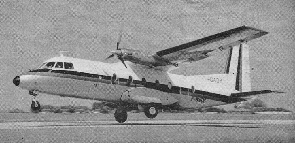
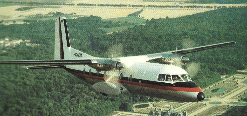
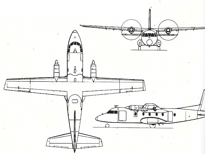
Ten MH260 with its rectangular section fuselage were built by Nord Aviation as the Nord 260. In 1961 started a significant redesign of the Nord 260. This resulted in the Nord 262 that had a redesigned fuselage with a circular cross section, pressurisation and more powerful powerplants. On 24 December 1962, this pressurised Nord 262 made its first flight.
The first production aircraft, F WKVA, flew in time to be exhibited at the Paris Aero Show in June 1963.
Air Inter, the French domestic airline, was expected to be the first operator of the Nord 262 pressurized version of the Nord 260.
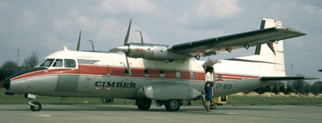
The first Nord 262 for Climber Air – 1967
On 1 January 1970, the main three French nationalised aircraft companies – Sud-Aviation, Nord Aviation and the missile manufacturing company, SEREB – were merged into Aérospatiale. As a result of this merger the Nord 262 became a product of Aérospatiale. The Nord 262 became the Aerospatiale Fregate turboprop.
The 262A was powered by two Turbomeca Bastan VIC. The 262B designation was for the first four production aircraft. Aerospatiale developed the improved 262C Fregate, with more powerful Bastan VII engines and new wingtips that increased wingspan by 2 ft 3.5 in (0.70m). The generally similar military 262D Fregate or Frigate D was produced.
In 1964 Lake Central Airlines was buying eight Nord 262 to replace DC-3s in its fleet, with an option of eight additional.
When production ended in 1976, a total of 110 Nord 262 were built.
Mohawk Air Services, a subsidiary of Allegheny Airlines Inc., Washington D.C., was formed to control a conversion program for the Mohawk 298, UACL PT-6A-45-powered Nord 262 airliner, being undertaken by Frakes Aviation Inc. The first example flew on January 7,1975.
N.262A Engines: 2 x Turbomeca Bastan VIC, 1080 shp / 805 ekW Wingspan: 71 ft 10.25 in / 21.90 m Wing area: 592.03 sq.ft / 55.00 sq.m Length: 63 ft 3 in / 19.28 m Height: 20 ft 4 in / 6.20 m Empty operating weight: 15,498 lb / 7030 kg MTOW: 23,369 lb / 16,600 kg Max speed: 239 mph / 385 kph Cruise: 233 mph / 375 kph Service ceiling: 23.500 ft / 7165 m Range no res: 864 mi / 1390 km Crew: 2 Passenger capacity: 29
Nord N 262 D Frégate Engine: 2 x Turboméca Bastan VIII A, 1341 shp Length: 63.255 ft / 19.28 m Height: 20.374 ft / 6.21 m Wingspan: 71.85 ft / 21.9 m Max take off weight: 23373.0 lb / 10600.0 kg Max. speed: 226 kts / 418 km/h Service ceiling: 26247 ft / 8000 m Range: 567 nm / 1050 km Crew: 2 Payload: 29 pax
Fregate Engines: 1045shp Max cruise: 225 mph Econ cruise: 192mph Stall: 80mph Fuel cap: 3530lb Service ceiling: 25,750 ft SE service ceiling: 13,500ft ROC: 1160fpm SE ROC: 500fpm Min field length: 2575ft Payload with full fuel: 4209 lb Max range: 965sm Max payload: 5867 lb Pressurisation diff: 4.2psi Seats: 29 Gross wt: 22,100 lb Equipped empty wt: 14,555 lb Useful load: 7545 lb
Development of a 17-seat light commuter airliner, known as the M.H.250 Super Broussard started in 1957. The prototype of the MH250, powered by two Pratt & Whitney Wasp-1830 piston engines, flew first on 20 May 1959. It was soon realised that turboprops should be employed and further development resulted in the MH260 with enlarged fuselage and powered by Turboméca Bastan turboprops. In October 1959, Avions Max Holste entered into a co-production arrangement with Nord Aviation so that the new aircraft could be manufactured. The prototype of the M.H.260, the F-WJDV, flew on 29 July 1960. Ten MH260 with its rectangular section fuselage were built by Nord Aviation as the Nord 260. In 1961 started a significant redesign of the Nord 260. This resulted in the Nord 262.
Air Inter, the French domestic airline, was expected to be the first operator of the Nord 262 pressurized version of the Nord 260, formerly known as the Super Broussard. Four Nord 262s were ordered by Air Inter.
Production of the Nord 260 was virtually complete in 1963, having totalled ten in addition to the prototype F WJDV. The first eight of the production batch were registered as follows: No. 1 F-WJSN trials aircraft No. 2 F BKRB Nord demonstrator No. 3 F BKRH Air Inter trials, 1963 No. 4 F BKSS Air Inter trials, 1963 No. 5 LN LMB Leased to Wideroe No. 6 F BLGP No. 7 F BLHN No. 8 LN LME Leased to Wideroe
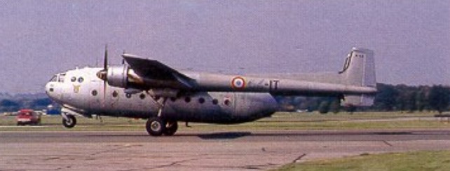
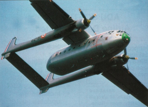
Designed as a military transport for service with the French air force, the Nord 2500 Noratlas prototype (F-WFKL) was flown for the first time on 10 September 1949. Of similar twin-boom configuration to the Fairchild C-82 and C-119 Flying Boxcar, the prototype was powered by two 1212kW SNECMA-built Gnome-Rhone 14R radial engines. This was followed by two N 2501 prototypes which introduced the powerplant intended for production aircraft, comprising two 1521kW SNECMA-built Bristol Hercules 739 radial engines, and the first of these (F- WFRG) was flown on 28 November 1950.
Satisfactory testing led to the initiation of production, and the Noratlas became standard equipment in the air forces of France, West Germany and Israel, providing valuable long-term service. Operated normally by a crew of four or five, the Noratlas has the capacity for 7.5 tons of cargo, or can accommodate 45 troops (or passengers in civil use), 36 fully-equipped paratroopers, or 18 stretchers and medical attendants when used for casualty evacuation. The German Luftwaffe received a total of 186 of these transports, 25 built by Nord and the balance produced under licence in Germany by the Flugzeugbau Nord. When production ended in October 1961, French and German sources had built a total of 425 Noratlas aircraft in several versions, and the type remained in service until the late 1980s.
Nord 2501 Engines: 2 x SNECMA Hercules 730, 1521kW / 2012 hp Max take-off weight: 21000 kg / 46297 lb Empty weight: 13075 kg / 28826 lb Wingspan: 32.5 m / 106 ft 8 in Length: 21.95 m / 72 ft 0 in Height: 6.0 m / 19 ft 8 in Wing area: 101.2 sq.m / 1089.31 sq ft Max. speed: 238 kts / 440 km/h / 273 mph Service ceiling: 7500 m / 24600 ft Range: 3000 km / 1864 miles Crew: 4-5 Passengers: 45 Payload: 8458kg
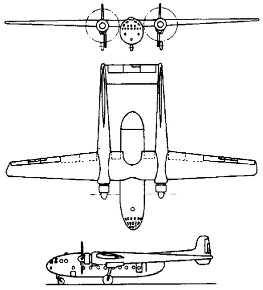
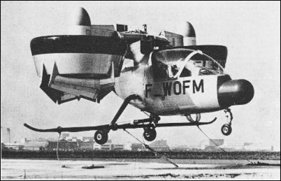
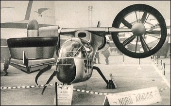
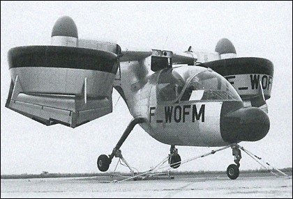
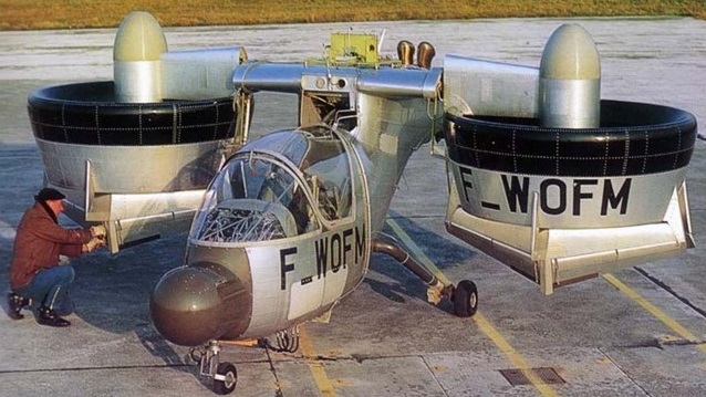
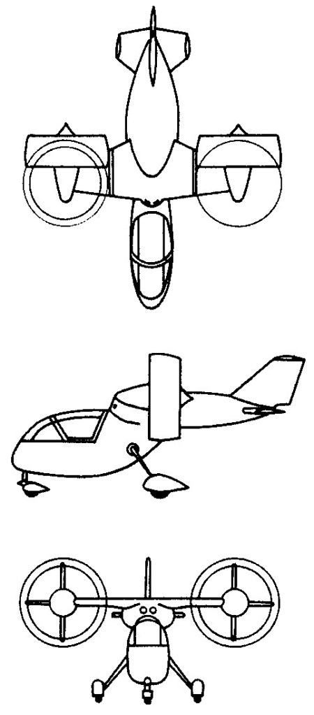
The Nord 500 was a single seat, company funded research aircraft. Its mission was to evaluate principles of the Tilt Duct propulsion concept for VTOL aircraft. The enclosed cabin contained an ejection seat. Two 317hp Allison T63-A-5A (or Allison T63-A5T, or 250-C18, depending on the source) turboshaft engines were located side by side in the rear part of the fuselage. They drove two 1.5m diameter props through interconnected shafts. Moveable vanes in the propeller slipstream controlled the duct positions aerodynamically. There were no other mechanical controls for rotating the ducts. The ducts tilted, along with a short section of wing. During hover, control in roll was by differential thrust, while control in pitch was by collective tilting of the ducts. There was no provision for attitude control of the fuselage because the ducts pivoted freely. The intended top speed was 218 miles per hour.
The first prototype was completed in Spring 1967 and was used for mechanical and ground tests. The second prototype made its first tethered flight during July 1968.
Nord merged with the Aerospatiale Corporation in about 1970, and the aircraft became known as the Aerospatiale N 500. Although a more sophisticated and more powerful version was in planning, all efforts on the Nord 500 appear to have stopped by 1971.
Nord-500 Engine: 2 x Allison T-63-A-5A turboshaft, 233kW Wingspan: 6.1m Length: 6.6m Height: 3.1m Max take-off weight: 1200kg Max speed: 350km/h
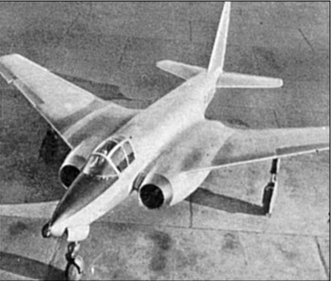
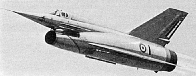
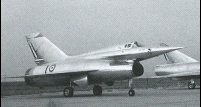
Under the designation Nord 1601, Nord designed a single-seat twin turbojet-powered aircraft to investigate the aerodynamic capability and efficiency of swept wings and related high-lift devices. A cantilever mid-wing monoplane with 33° of sweepback on the wing leading edges, the N 1601 had a wing incorporating ailerons, spoilers, leading-edge slats and trailing-edge flaps. The configuration included swept tail surfaces, and there were retractable tricycle landing gear and two 1814kg thrust Rolls-Royce Derwent 5 turbojet engines in underslung wing-mounted nacelles on each side of the fuselage. The pilot was accommodated on a Martin-Baker ejector seat in a cockpit enclosed by a jettisonable canopy. The aircraft was first flown on 24 January 1950, and the research programme of the 12.46m span N 1601, which had a maximum speed of 1000km/h and a ceiling of 12000m, provided valuable design information. An all-weather fighter version of this aircraft was allocated the project number N 1600 but was not built.
Nord 1601 Engines: 2 x Rolls-Royce Derwent 5 turbojets, 1814kg Wingspan: 12.46 m / 41 ft 11 in Max. speed: 1000 km/h / 621 mph Ceiling: 12000 m / 39350 ft
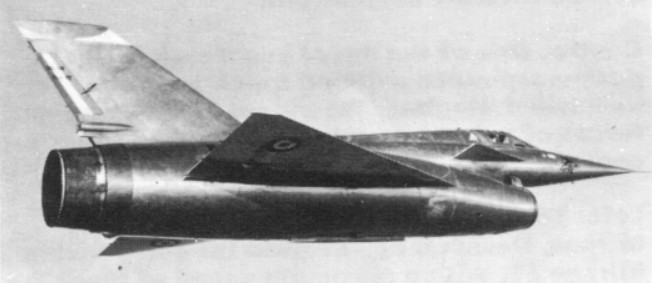
The Gerfaut lB and Gerfaut II prototypes paved the way for the N.1500 Griffon prototype of interceptor potential. After early tests of the Gerfaut la, Nord designed and built the Nord 1500-01 Griffon I research aircraft, which was intended to flight-test a combined turbojet-ramjet power unit. A delta wing aircraft with 60 degrees of sweepback on the leading edge, the N 1500 had elevons for control in pitch and roll. Thus the tail unit comprised only swept vertical surfaces, and fixed foreplanes were mounted on each side of the forward fuselage.
This flew on 20 September 1955 with a 4100kg thrust SNECMA Atar 101G21 afterburning turbojet, but was soon fitted with the planned combination powerplant comprising a 3800kg thrust Atar 101F turbojet and a Nord ramjet to produce the Griffon II and achieved Mach 1.85 in 1957. This was capable of supersonic performance on its ramjet, but was not developed into an operational type.
At the completion of initial testing the airframe was modified to accept a 3500kg thrust Atar 101E3 turbojet within the ducting of an integral ramjet of Nord design, the turbojet being located just forward of the ramjet burners. Then redesignated N 1500-02 Griffon II, it was flown first on 23 January 1957, completing more than 200 test flights before the Nord research programme ended in 1959.
27 October 1958 pilot Andre Turcat set closed circuit speed record of 1,638 kmh. On 25 February 1959 it set a 1018 mph, world speed record over a 100 km closed course and 13 October 1949 saw 1448 mph at 50,000 ft.
Some testing was carried out under USAF research contract.