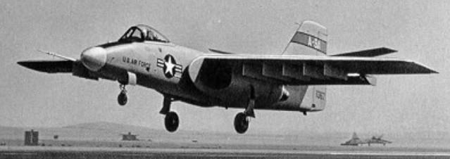
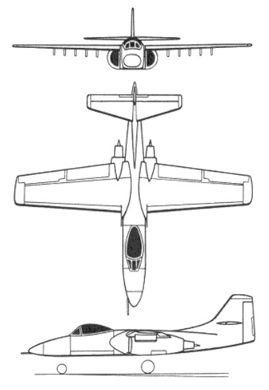
Under the designation Northrop YA-9A, the company built two prototypes (71-1367 and 71-1368) of a single-seat close-support aircraft as the company’s submission for the competitive development phase of the USAF’s A-X close-support aircraft competition in late 1972. Designed by Robert Bratt, Walt Fellers, Don Heinze, and Jerry Huben, the A-9 was a cantilever high-wing monoplane, powered by two 2722kg thrust Avco Lycoming ALF 502 turbofan engines, the first of the prototypes made its maiden flight on 30 May 1972 piloted by Lew Nelson. In competitive evaluation the YA-9A lost out to the YA-10A by Fairchild Republic.
Northrop A-9A 71-1367
Both of the A 9s built were passed on to NASA for further tests and were later retired to museums.
The first YA 9A built, 71 1367, first flew on May 30, 1972 and at the end of its military career was put on display at the Castle Air Force Base Museum, until its move back to Edwards.
In the storage yard at Edwards AFB on April 7, 2006. Previously on display at Castle AFB
Engines: 2 x Lycoming F-102-LD-100, 33.4kN / 7500 lb Max take-off weight: 18160 kg / 40036 lb Empty weight: 10318 kg / 22747 lb Wingspan: 17.7 m / 58 ft 1 in Length: 16.3 m / 53 ft 6 in Height: 5.2 m / 17 ft 1 in Wing area: 54.9 sq.m / 590.94 sq ft Max. speed: 740 km/h / 460 mph Cruise speed: 322 mph Ceiling: 40,000 ft Range w/max.fuel: 4800 km / 2983 miles Armament: 1 x 30mm machine-guns, 7264kg of bombs and missiles Crew: 1
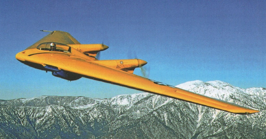
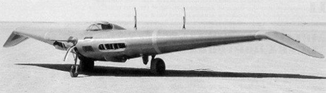
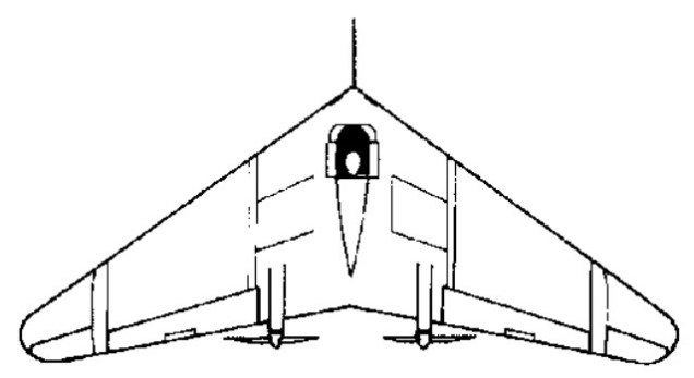
In January 1943, Northrop was awarded a USAAF contract for the design and construction of three prototypes of a highly original rocket-propelled interceptor fighter of all-wing configuration and designated XP-79. By 1944 Northrop had a range of projects stemming from the MX 324, including Ram Wing. This was a true flying wing with tip duct bellows spoilers, and a pilot lying prone to fit within the wing pro¬file and withstand violent combat manoeuvres. To be powered by a single 907kg Aerojet rocket motor, the XP-79 was to have accommodated its pilot in the prone position, but, in the event, development problems with the rocket led to cancellation of the project. However, a contract was placed for the redesign of the fighter for turbojet power, one prototype being ordered as the XP-79B.
It was schemed in various forms but the basic concept was that the wing should have a leading edge of thick magnesium endowing it with exceptional impact strength. Unlike almost every other flying machine in history the XP 79 was planned with mid air collision as a basic design case. Its four 0.50in guns were officially called “secondary”. There were still no powerful rocket motors and Northrop built the XP 79B with two of the new turbojets.
The engines chosen were the 19 inch Westinghouse Navy axials, which as the pre production J30 (model 19B) were each rated at about 1,150 1b / 619kg. This was judged enough to make the 8,670 lb XP 79B a practical proposition, and technically it was a design of exceptional interest. The pilot was accommodated in a modified cradle, stressed for sustained 12g manoeuvres, with an engine close on each side. To overcome the nose gear problem there was “a wheel at each corner”, each leg folding into the wing. After testing with no fin or with a central fin it was decided to fly with a fin above each jet. The aircraft that bore AAF serial 43 52437. It was delivered to Muroc in June 1945 to start testing with Harry Crosby as a test pilot.
Flown for the first time on September 12, 1945, after several days of preliminary tests, an incident marked the beginning of the flight when an Army Air Force fire truck crossed runway. Crosby had time to cut the power to avoid the collision, then he climbed to 10,000 feet. Crosby seemed quite at home, and flew confidently for 15 minutes. He returned to his take-off area by describing a large circle with a particularly high speed (estimated at more than 400 mph). On his second pass over the salt lake, Crosby started a climbing turn, then the Ram Wing went into an agonizingly slow roll and went straight into the ground in “a steep vertical spin”. Crosby was seen jumping at the last moment but was struck by a portion of the plane. His parachute never opened. The cause was attributed to a hard over runaway by the electric trim tab in the lateral control system. As the war was over ramming was dropped.
XP-79B Wingspan: 11.58 m / 37 ft 12 in Length: 4.27 m / 14 ft 0 in Height: 2.13 m / 7 ft 0 in Wing area: 25.83 sq.m / 278.03 sq ft Max take-off weight: 3932 kg / 8669 lb Empty weight: 2649 kg / 5840 lb Max. speed: 880 km/h / 547 mph Range: 1600 km / 994 miles Service ceiling: 40,000 ft / 12 000 m Rate of climb: 4,000 ft/mn / 1 220 m/mn Crew: 1
The Northrop P-61 Black Widow began in August 1940, at the height of the Blitz on London. During this time, the US air officer in London, Lt. Gen. Delos C. Emmons, underwent a briefing on British progress on radar. British scientists and engineers were at that time working on the early versions of AI (Airborne Interception) radar sets which could be carried aboard airplanes, enabling them to detect and intercept other airplanes in flight without having to rely on ground installations.
At the same time, the British Purchasing Commission that was shopping for aircraft in the USA announced that they urgently required a night fighter that would be capable of stopping the German bombers that were attacking London by night. Such a fighter would have to be able to stay on station above London all night, which meant at least an 8-hour loiter time. In addition, the night fighter needed to have sufficient combat altitude in order to take on the bombers when they showed up.
When General Emmons returned to the USA, he reported that the British had an urgent need for night fighter aircraft, and that American industry might be able to supply that need. A preliminary specification was drawn up by the Emmons Board and was passed on to Air Technical Service Command at Wright Field in late 1940. Because of the heavy weight of the early AI radar and because of the high loiter time required, a twin-engined aircraft was envisaged.
Northrop Chief of Research Vladimir H. Pavlecka happened to be at Wright Field at that time on an unrelated project, and was told of the Army’s need for night-fighters. However, he was told nothing about radar, only that there was a way to “see and distinguish other airplanes”. He returned to Northrop the next day. On October 22, Jack Northrop met with Pavlecka and was given the USAAC’s specification. At this time, no other company was known to be working on night fighters, although at about this time Douglas was starting work on their XA-26A night fighter and the AAC were considering the A-20B as an interim night fighter.
Northrop’s proposal was a twin-engined monoplane powered by a pair of Pratt & Whitney R-2800 Double Wasp air-cooled radial engines mounted in low-slung nacelles underneath the wings. The nacelles tapered back into twin tail booms which were connected to each other by a large horizontal stabilizer and elevator. The long fuselage housed a crew of three. The crew consisted of a pilot, a gunner for the nose turret, and a radar operator/rear turret gunner. Each turret housed four 0.50-inch machine guns. A tricycle landing gear was fitted. Estimated weights were 16,245 pounds empty, 22,654 pounds gross. Height was 13 feet 2 inches, length was 45 feet 6 inches, and wingspan was 66 feet. These dimensions and weights were more typical of a bomber than a fighter.
On November 14, Northrop presented this revised design to the USAAC. An additional gunner’s station was fitted. Nose and tail turrets of the original version were replaced by twin 0.50-in machine guns in the belly, and four 0.50-in machine guns in a dorsal turret. The crew was now up to four-a pilot, a radar operator, and two gunners. The airborne intercept radio was moved to the nose.
The design was revised still further on November 22. The belly turret was deleted, and the crew was changed back to three-pilot, gunner, and radar operator. The pilot sat up front, and the gunner sat immediately behind and above the pilot. The gunner was to operate the turret via remote control, using a special sight attached to a swiveling chair. A “stepped-up” canopy was used to provide a clear field of view for the gunner. The rear fuselage with its clear tail cone provided the radar operator with an excellent rearward view which enabled him to act as a tail gunner if the plane happened to be attacked from astern. Optionally, the dorsal turret guns could be “locked” into the forward-pointing position, so that they could be fired by the pilot. The belly guns were deleted, and four 20-mm cannon were to be fitted in the wings. This design was formalized into Northrop Specification 8A (or NS-8A), dated December 5, 1940.
Incorporated into the night fighter design was the Zap wing and Zap flap, named after Edward Zap, a Northrop engineer. These were attempts to increase the maximum lift coefficient and to decrease the landing speed by the use of improved lateral control and lifting devices
NS-8A was submitted to Wright Field. The Army was generally pleased with the design, but they suggested some changes. A letter of quotation prepared by Northrop for two experimental prototypes was presented to Materiel Command on December 17, 1940. Northrop signed the formal contract on January 11, 1941. A contract was let on January 30, 1941 for two prototypes and two wind-tunnel models. On March 10, 1941, a contract was issued for 13 YP-61 service test aircraft, plus one engineless static test airframe.
The mockup was ready for inspection in April of 1941. At that time, it was decided to move the four 20-mm cannon from the outboard portion of the wings to the belly. This was done to improve the ease of maintenance and to make the airflow over the wing smoother. The internal fuel capacity was increased from 540 gallons in two tanks to 646 gallons in four self-sealed tanks built into the wings.
In the meantime, development of the A/I radar had proceeded at a rapid pace. Radar development in the United States had been placed under the control of the National Defense Research Committee. The NDRC’s Microwave Committee in turn had established the Radiation Laboratory at the Massachusetts Institute of Technology. The Radiation Laboratory was to handle the development of the XP-61’s airborne interception (AI) radar. The designation of the radar was AI-10. The AI-10 radar was given the military designation SCR-520, where SCR stood for “Signal Corp Radio” (some references have this as standing for “Searchlight Control Radar”). The Western Electric corporation was assigned the responsibility of refining the design and undertaking the mass production of the radar.
In October 1941, a pedestal-type mount for the turret guns was substituted for the General Electric ring-type mount.
A letter of intent was initiated on December 24, 1941, which called for 100 P-61 production aircraft and spares. Fifty more were ordered on January 17, 1942. The order was increased to 410 aircraft on February 12, 1942, fifty of which were to be diverted to the RAF under Lend-Lease. The RAF order was eventually cancelled. The XP-61 flew at Northrop Field for the first time on May 26, 1942, piloted by contract test pilot Vance Breese. It was powered by a pair of Pratt & Whitney R-2800-10 radials of 2000 hp each. In keeping with its nocturnal role, it was finished in black overall, befitting its popular name that was taken from the poisonous North American spider. Wingspan was 66 feet, length was 48 feet 10 inches, and height was 14 feet 2 inches. Weights were 19,245 pounds empty, 25,150 pounds gross, and 28,870 pounds maximum. The aircraft was equipped with only a mockup of the top turret, as General Electric had not yet been able to deliver the real thing because of the higher priority of other projects.
The XP-61 had a maximum speed of 370 mph at 29,900 feet, and an altitude of 20,000 feet could be attained in 9 minutes. Service ceiling was 33,100 feet, and maximum range was 1450 miles.
In mid-June 1942, a new horizontal tail was designed to complement the full-span flaps. Eventually, the Zap flaps were completely eliminated because of their high cost and complexity of manufacture, and spoilers were added to supplement the conventional ailerons. The spoilers were located in the rear one-third of the wing, and were one of the most successful innovations introduced during the entire Black Widow program. Operating in conjunction with the conventional ailerons, the spoilers provided the desired rolling moment at speeds even below the stalling speed. Although the spoilers were fully capable of providing all necessary lateral control on their own, the ailerons were nevertheless still left on the airplane if only to provide “warm fuzzies” to pilots who were used to conventional ailerons.
On May 25, 1942, an agreement was reached between Northrop and the USAAC to produce 1200 P-61s at a government facility in Denver, Colorado. By the end of July, that order had been cut down to 207 aircraft and it was decided that the Northrop facilities at Hawthorne were to be used after all.
The thirteen YP-61s were delivered during August and September of 1943. In order to reduce vibrations from firing the 0.50-inch turret machine guns, some YP-61s were fitted with only two turret guns. The assignments of the YP-61s were varied. Some stayed at Northrop for flight testing and factory training of maintenance personnel. Some went to Wright Field in Ohio for service testing. Others went to Florida where they underwent operational suitability testing.
The YP-61s initially did not have any airborne interception radar fitted, but the SCR-520, a preproduction version of the SCR-720 which was to go into the production P-61A, was installed.
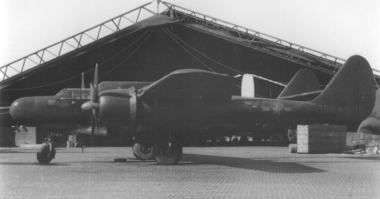
Northrop P-61A-5NO 42-5549, 9th AF
It made its operational debut in the South Pacific in the summer of 1944 and was the standard USAAF night fighter at the end of the war. Unlike other USAAF fighters such as the P-47 Thunderbolt or P-51 Mustang, the Black Widow did not chalk up a particularly impressive number of kills, because by the time of its entry into service, the Allies had already established almost overwhelming air superiority over virtually all fronts, and enemy aircraft were rather few and far between, especially at night.
The F-15A two-seat strategic reconnaissance variant first flew in 1946.
P-61A Engines: 2 x Pratt & Whitney R-2800-10, 2000 hp Wingspan: 66 ft / 20.12 m Length: 48 ft 11 in / 14.92 m Height: 14 ft 8 in / 4.49 m Empty weight: 24,000 lb / 10,886 kg Max loaded weight: 32,400 lb / 14,696 kg Max speed: 366 mph / 590 kph ROC: 2200 fpm / 670 m/min Service ceiling: 33,000 ft / 10,060 m Range max fuel: 500 mi Armament: 4 x 20mm M-2 cannon (belly), plus in first 37 A: 4 x 0.5in dorsal
P-61B Engines: 2 x Pratt & Whitney R-2800-65 Double Wasp, 1491kW / 2219 hp Wingspan: 20.12 m / 66 ft 0 in Length: 15.11 m / 49 ft 7 in Height: 4.47 m / 14 ft 8 in Wing area: 61.53 sq.m / 662.30 sq ft Max take-off weight: 16420 kg / 36200 lb Empty weight: 10637 kg / 23451 lb Max. speed: 589 km/h / 366 mph ROC: 2200 fpm / 670 m/min Ceiling: 10090 m / 33100 ft Range: 2173 km / 1350 miles Range max fuel: 2800 mi / 4500 km Bombload: 6400 lb Armament: 4 x 20mm M-2 cannon (belly), plus in last 250 B: 4 x 0.5in dorsal Crew: 3
P-61C Engines: 2 x Pratt & Whitney R-2800-73, 2800 hp Wingspan: 66 ft / 20.12 m Length: 49 ft 7 in / 15.1 m Height: 14 ft 8 in / 4.49 m Empty weight: 24,000 lb / 10,886 kg Max loaded weight: 40,300 lb / 18,280 kg Max speed: 430 mph / 692 kph ROC: 3000 fpm / 914 m/min Service ceiling: 41,000 ft / 12,560 m Range max fuel: 2800 mi / 4500 km Bombload: 6400 lb Armament: 4 x 20mm M-2 cannon (belly), 4 x 0.5in dorsal
F-15 2 seat strategic reconnaissance Engines: 2 x Pratt & Whitney R-2800-73, 2800 hp Wingspan: 66 ft / 20.12 m Length: 50 ft 3 in / 15.3 m Height: 14 ft 8 in / 4.49 m Empty weight: 22,000 lb / 9979 kg Max loaded weight: 28,000 lb / 12,700 kg Max speed: 440 mph / 708 kph ROC: 3000 fpm / 914 m/min Service ceiling: 41,000 ft / 12,560 m Range max fuel: 4000 mi / 6440 km Armament: none
Faced with the distinct possibility of a British defeat in the war in Europe, America’s most pressing need in 1941 was for a bomber with intercontinental range which could strike Germany and return home. The US Army gave the go ahead for an aircraft which spanned 52.4 m (172 ft), had a gross weight of 78,845 kg (165,000 lb) and could carry a 23,225 kg (51,200 lb) bombload. Four 3000 hp Pratt & Whitney Wasp Major engines driving contra rotating pusher propellers powered the aircraft which had a crew of 15 and was to have been defended by 20 remotely controlled 12.7mm (0.5 in) machine guns.
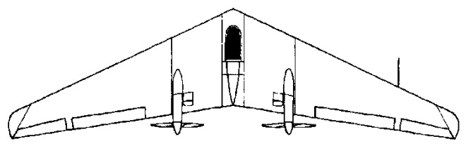
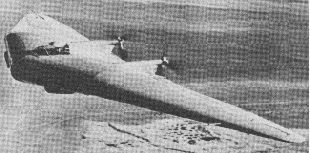
By mid 1941 Northrop was well advanced with a far more ambitious design based on the encouraging results obtained with the N-1M. This design was for a flying wing bomber.
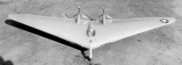
The scale model of the bomber was designated N 9M. This was approximately a one third linear scale of the great bomber, and thus weighed about 1/27th as much, the actual weight being of the order of 7,100 lb. The first two aircraft, and the third (designated N 9M A), had two 275 hp Menasco Buccaneer engines driving pusher propellers positioned midway between the thrust lines of the four propellers of the bomber; the fourth aircraft, designated N 9M B, had two 300 h.p. Franklins. The fact that four aircraft were needed is explained by the sheer volume of work that had to be accomplished. Not only was the definitive form of surface system controls and flaps far from settled, but there were also extensive development programmes for autopilot and other systems, while concurrently exposing the aircraft to the hands of the greatest possible number of Army test pilots in order both to acquire critical feedback from the customer and also allay a whole string of fears about how all wing aircraft behaved.
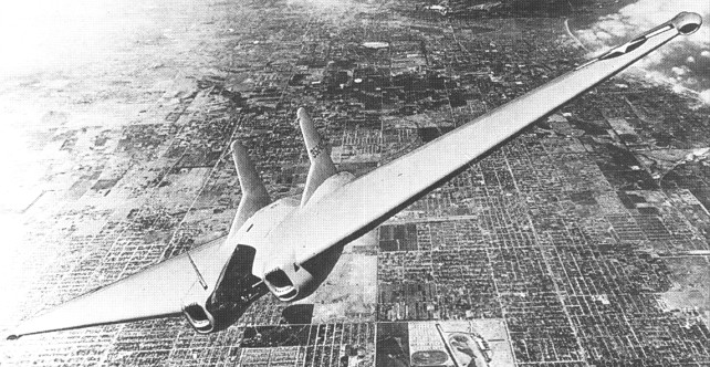
N9MB
The first N 9M was flown on December 27, 1942. After about 30 encouraging hours it crashed, killing the pilot. Nobody had the slightest indication of what happened. Northrop could not find evidence of in flight failure and decided the pilot must have got into a spin at low level. The other three N 9Ms gave no trouble at all, and in the course of many hundreds of hours were stalled and spun even with c.g. at the aft limit.
A three-year test programme was flown from Muroc Army Air Base, providing much data and giving pilots experience in the handling and performance of flying wings, and the autopilot for the XB-35 was developed in an N-9M. All N-9Ms had retractable landing gear and varying colour schemes; the first two were all yellow, the third (N-9MA) was blue on top and yellow underneath, while the fourth (N-9MB) had the colour reversed. The colours identified the top or bottom of the aircraft during observations of the flight programme.
N 9M A Engines: two 205kW / 275 hp Menasco Buccaneer
N-9MB Engines: 2 x Franklin 224kW / 300 hp Max take-off weight: 3200 kg / 7055 lb Wingspan: 18.3 m / 60 ft 0 in Length: 5.3 m / 17 ft 5 in Wing area: 46 sq.m / 495.14 sq ft Crew: 1
Northrop began to build one flying wing in 1939, designating it N 1M (Northrop model Mock up). Essentially it was just a 38 foot stressed skin wing, with a very fat section (and as much camber underneath as on top) and a slightly swept back shape. The upper surface had very slight dihedral, so that there was quite sharp dihedral on the underside, but the tips sloped sharply downwards so that the ailerons, which were entirely out¬board of the kink, could also serve as rudders. On the trailing edge were powerful elevators incorporating trim¬ming tabs. The pilot sat close to the centre of gravity, his head projecting above the upper surface under a small canopy and his forward vision being improved by four small windows in the remarkably fat leading edge. Just outboard of these windows were intakes for the cooling air for the two 65 hp Lycoming engines, which were buried in the wing and drove pusher propellers through 10 foot shafts housed in fairings which made no contribu¬tion to lift but which Northrop could not avoid. The N 1M rode on a short wheelbase retractable tricycle landing gear, with a long fixed tailwheel added to, keep the propellers from touching the ground.
Northrop bore most of the costs of building it himself, but in view of its long term importance he did not invite the press in to have a look at it. Indeed he had already come to the conclusion that the ideal role for an all wing machine was that of a long range bomber, and had discussed the possibility with the Army Air Corps and with the top technical staff at Wright Field. They were extremely interested, and it was agreed that the N-1M should be kept under wraps.
In May 1940 the completed machine was painted bright yellow, registered as NX 28311 and trucked by night from the plant at Hawthorne to the very new Army test base at Lake Muroc out in the remote Mojave Desert. Pilot Vance Breese tried taxying and then, on July 3, cautiously lifted off and held the yellow wing as close to the ground as he could as someone said, “to make the crash a bit easier”. Northrop’s comment was “It looks like we have a plane with a twenty foot ceiling”, but of course Breese later made proper flights which on the whole were remarkably successful. There was no catastrophic accident, and the N-1M explored a wide range of configurations with different planform, dihedral, tip shape, c.g. location and, most important of all, control system. Soon it was flying much faster with 117 h.p. Franklin 6AC 264 F2 engines driving three blade v p propellers.
The N 1M really flew extremely well, in the hands of several pilots (notably Moye Stephens), and the only persistent difficulty was the cooling of the engines. Ordinary flying had by mid 1941 become a safe and routine operation, with the whole design envelope, including stalls and spins, fully explored in 200 flights. The only control “problem” was that it took a long time to find the best arrangement to control yaw (weathercocking of the nose, for example, due to asymmetric thrust). The original idea of using the ailerons on the down turned tips to serve as rudders was not wholly adequate, and eventually Northrop considered the best answer was to eliminate the kinked tips and make the ailerons in the form of split upper and lower halves which could be opened to act as a powerful brake. With just one aileron thus opened there would be an extremely potent yawing moment amply capable of holding any asymmetric condition.
The N-1M has survived in the US National Air and Space Museum.
N-1M Engine: 2 x Lycoming, 48kW / 65 hp Max take-off weight: 1360 kg / 2998 lb Wingspan: 11.6 m / 38 ft 1 in Length: 5.2 m / 17 ft 1 in Wing area: 28 sq.m / 301.39 sq ft Crew: 1
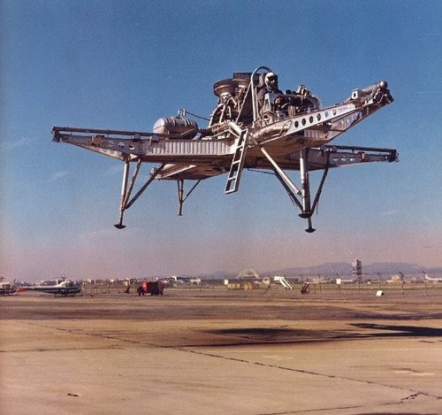
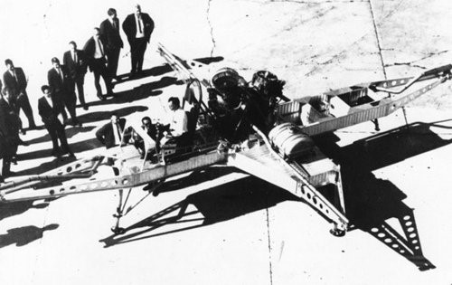
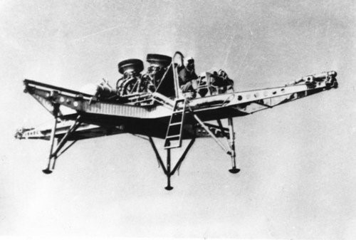
The North American FS-1 (Flight Simulator Number 1) Hoverbuggy was a 1965 open framework VTOL research vehicle with two 2200 lb GE YJ85 turbojets for lift, and four engine bleed-air nozzles on outriggers for control.
The craft had made 15 tethered and 185 free flights at altitudes up to 100ft when the program was shut down in 1967.
Engines: two x GE YJ85, 2200 lb Span: 23’0″ Length: 36’0″ Useful load: 1550 lb Max speed: 58 mph Range 10 mi
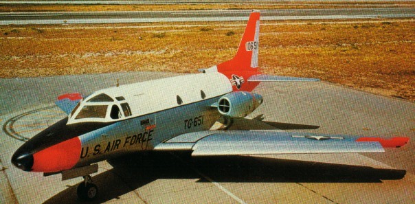
The NA-246 Sabreliner started its life as a private venture in the mid 1950s to meet the USAF’s UTX requirements for a combat readiness trainer and utility aircraft. Announced on 27 August 1956, It was laid out with a six-seat interior and to be flown by a two-man crew, the civil-registered prototype was completed in May 1958, although the lack of suitable engines delayed the first flight, which took place at Los Angeles, until 16 September, under the designation T 39. The initial powerplant comprised two 1134kg thrust General Electric YJ85 turbojets and, thus powered, the prototype completed its military evaluation programme at Edwards Air Force Base in December 1958.
In October 1958 the Sabreliner won its first order, for seven NA-265 or T-39A aircraft with 1361kg thrust Pratt & Whitney J60 engines. Production of the highly successful T 39 series commenced in 1958, and 213 were purchased by the Air Force and the Navy. All military models of the T-39 series were certificated to civil airworthiness standards, beginning with the T-39A on 23 March 1962.
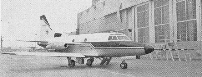
The commercial version of the T 39, known as the NA-265-40 Sabreliner / Sabre 40, was type certificated on 17 April 1963 and was one of the first jets available to business aviation. It is larger and more rugged and powerful than jets that have been designed solely for civilian use. Its speed by jet standards is modest with a cruise of 489 knots. The aircraft maintained its popularity throughout the 1960s and 1970s as improvements were made to the airframe and powerplants.
In 1965 North American increased the Sabreliner’s gross weight by beefing up landing gear and re-qualifying wheels. The modification allows the twin-jet to carry full fuel with nine people and baggage aboard totalling 18,650 lb. The previous max was 17,760 lb. Changes were offered free to Sabreliner owners.
One of the unusual features that the Sabreliner was automatic leading edge slats. The slats added impressive low speed handling qualities to the bizjet.
Gone are the slats, however, from a Sabreliner 60. The stretched Sabre 60, introduced in 1969, is powered by two 3,300 pound thrust P&W JT12A 8 turbojets, the same engine that was used in the Dash 8 JetStar.
The Rockwell Sabreliner 65 is essentially a fanjet, supercritical wing version of the Sabre 60. Its engines are Garrett AiResearch TFE 731-3s, which the factory may also retrofit to Model 60s and the even earlier Sabre 40s. Its IFR range was just under 2,500 nautical miles. The first production lot of Sabre 65s was sold at an average equipped price of $3,250,000.
Both the 74 and 60 models were fitted with thrust reversers to aid in shorter landings and assist in braking on icy or wet runways.
75A
The Sabre 75A, with its expanded cabin height and higher gross weight, uses two General Elec¬tric CF700 2D2 turbofans identical to the 4,315 pound thrust powerplants employed on the Falcon 20. The 75A model features square windows, a ‘stand-up’ cabin and a long span tailplane.
In 1978 Rockwell International’s Sabreliner 80A made a first flight from St. Louis. The new business jet is a modified version of the Model 75A, with a supercritical wing.
Civil production of all models, including the final model, the Sabreliner 65A, totalled well over 600 aircraft when the last aircraft came off the line in 1981.
Rockewell International’s Sabreliner Division was acquired in 1983 by the specially formed Sabreliner Corporation of St Louis, Missouri to continue product support. Type Certificate A2WE was reissued to Saberliner Corp in 1983 to cover active Model 265s. At the end of 1990 the company completed the design of a new version of the Sabreliner designated the Model 85. This has a supercritical wing incorporating winglets, a fuselage stretch of 1.5m, and more powerful TFE731-5 turbofan engines, but further development would require a risk-sharing partner.
NA-246 Sabreliner / T-39 Engines: 2 x General Electric YJ85 turbojets 1134kg thrust
T-39 Engines: 2 x P&W Wing span: 44 ft 5 in (13.54 m) Length: 43 ft 9 in (13.34 m) Height: 16 ft 0 in (4.88 m) Max TO wt: 17,760 lb (8055 kg) Max level speed: 595 mph (958 kph)
NA 265-65 Sabreliner 65 Engines: 2 x Garrett TFE 731-3R-1D, 3700 lbs / 1678kg thrust Seats: 10 Length: 14.30 m / 46 ft 11 in Height: 4.88 m / 16 ft Wingspan: 15.37 m / 50.5 ft Wing area: 380 sq.ft Wing aspect ratio: 6.7 Maximum ramp weight: 24,000 lbs Maximum takeoff weight: 10886 kg / 24,000 lbs Standard empty weight: 13,350 lbs Maximum useful load: 10,650 lbs Zero-fuel weight: 16,250 lbs Maximum landing weight: 21,755 lbs Wing loading: 63.2 lbs/sq.ft Power loading: 3.2 lbs/lb Maximum usable fuel: 8644 lbs Best rate of climb: 3540 fpm Certificated ceiling: 13715 m / 45,000 ft Max pressurisation differential: 8.8 psi 8000 ft cabin alt @: 45,000 ft Maximum single-engine rate of climb: 950 fpm @ 127 kts Single-engine climb gradient: 452 ft/nm Single-engine ceiling: 25,000 ft Maximum speed: 513 kts Normal cruise @ 43,000ft: 430 kts Fuel flow @ normal cruise: 1090 pph Stalling speed clean: 117 kts Stalling speed gear/flaps down: 81 kts Turbulent-air penetration speed: 225 kts
Sabreliner 65A
Sabreliner 75A Engines: 2 x General Elec¬tric CF700-2D2, 4315 lb Seats: 8/10 Wing loading: 68.11 lb/sq.ft Pwr loading: 2.53 lb/lb Max TO wt: 22,800 lb Operating wt: 13,600 lb Equipped useful load: 9200 lb Payload max fuel: 1820 lb Zero fuel wt: 15,620 lb Range max fuel/cruise: 1985 nm/4.0 hr Range max fuel / range: 1897 nm/ 4.6 hr Service ceiling: 45,000 ft Max cruise: 489 kt Max range cruise: 417 kt Vmc: 92 kt Stall: 105-113 kt 1.3 Vso: 137 kt ROC: 4500 fpm SE ROC: 1050 fpm @ 190 kt SE Service ceiling: 24,000 ft Cabin press: 8.8 psi Fuel cap: 7380 lb Takeoff run (balanced) 4,420 ft Landing roll 2,525 ft
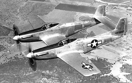
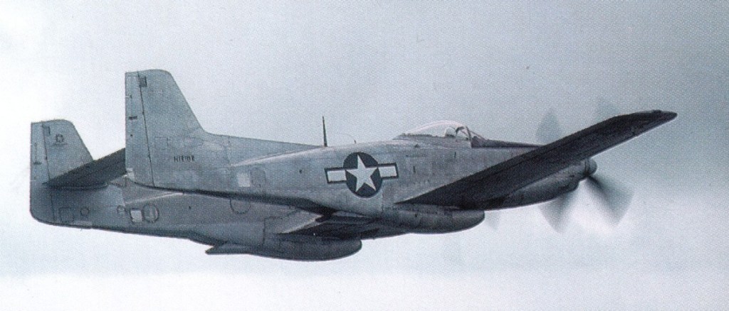
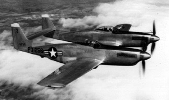
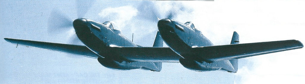
The long-range, high-altitude escort fighter, development of the P-51 Mustang, the Twin Mustang was formed by two fuselages joined by the wing and the horizontal stabilizer. The P-82 was a separate new design, not just a mating of P-51s, as commonly assumed. It was also the last prop-driven fighter to be ordered into production by USAF.
Two XP-82 (NA-120) prototypes were built (44-83886/83887) in 1945 powered by Packard-Merlin V-1650-23/25 with opposite rotating props. First flying at XP-82A on 15 April 1945.
With a pilot in each fuselage, it reduced the problem of pilot fatigue on ultra-long-range missions.
North American XP-82A 44-83888
One XP-82A (NA-120), 44-838881945, was built with Allison V-1710-119 engines.
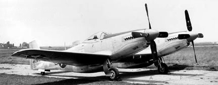
The P-82B (NA-123) of 1945 was the initial production version. Twenty were built, 44-65160-65179.
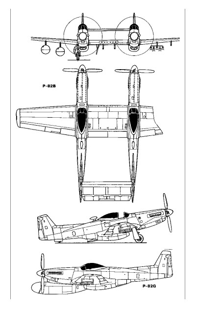
North American P-82B
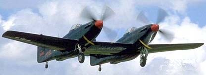
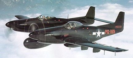
North American P-82C 44-65169
The NA-123 P-82C and -82D of 1946 were night fighter conversions of P-82Bs with a centre-section APS-4 radar pod.
North American P-82E 46-258
100 (46-255/354) of the P-82E / NA-144 escort fighter were built in 1946.
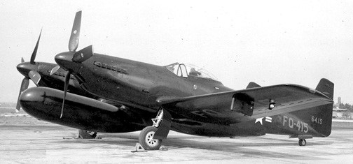
North American P-82F 46-415
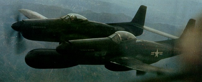
The P-82F (NA-149) and G models carried a radar operator in the right cockpit instead of a co-pilot. 100 P-82F (46-405/495) night fighter were built in 1946. 45 P-82G / NA-150 (46-355/383, -389-404) all-weather night fighter with tracking radar were built in 1946, powered by Allison V-1710-143.
An F-82G was credited with downing the first enemy aircraft in the Korean War (p: Lt William Hudson), on 27 June 1950.
F-82G
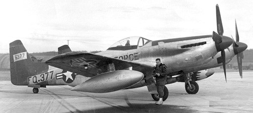
The P-82H of 1947 were Alaskan winterized conversions. Five were built from F-82F [46-384/388] and nine from F-82G [46-496/504].
North American P-82H 46-377
Re-designated F-82 in June 1948.
Although a few initial models had Merlin engines, the great majority were Allison powered and saw service in Korea.
P-82B. One of 20 initial production variants out of 500 ordered. Serialled 44-65162, restored as N12102
272 were built, the final delivery, an F-82G, in April 1949.
XP-82 / NA-120 Engines: 2 x Packard-Merlin V-1650-23/25 Props: Contra-rotating No built: 2 [44-83886/83887]
XP-82A / NA-120 1945 Engines: Allison V-1710-119 1 built 44-83888
F-82 Engine: 2 x Allison V-1710-143/145, 2300 hp Wingspan: 51 ft 3 in / 15.61 m Height: 13 ft 10 in / 4.2 m Armament: 6 x .50 mg Bombload: 2 x 4000 lb
P-82B / NA-123
P-82C / NA-123 1946 Night fighter conversions of P-82B with centre-section APS-4 radar pod. 1 built 44-65169
P-82D / NA-123 1946 Night fighter conversions of P-82B with centre-section APS-4 radar pod. 1 built 44-65170
P-82E / NA-144 1946 Escort fighter 100 built 46-255-354 Length: 39 ft 1 in / 11.88 m Height: 13 ft 10 in / 4.2 m Empty weight: 14,350 lb / 6509 kg Max loaded weight: 24,864 lb / 11,276 kg Max speed: 465 mph / 750 kph Range: 2504 mi Armament: 6 x .50 mg Bombload: 2 x 4000 lb
P-82F / NA-149 1946 Night fighter 100 built 46-405/495
P-82G / NA-150 Engine: 2 x Allison V-1710-143/145, 1600hp / 1193kW Wingspan: 15.62 m / 51 ft 3 in Length: 12.93 m / 42 ft 5 in Height: 4.22 m / 13 ft 10 in Wing area: 37.90 sq.m / 407.95 sq ft Max take-off weight: 11608 kg / 25591 lb Empty weight: 7256 kg / 15997 lb Useful load: 9594 lb Max. speed: 401 kt / 742 km/h / 461 mph Cruise speed: 285-300 mph Ceiling: 11855 m / 38900 ft Range w/max.fuel: 3605 km / 2240 miles Armament: 6 x 12.7mm machine-guns, 4x 454kg of bombs Crew: 2 45 built (46-355/383, -389-404)
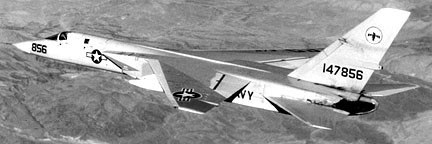
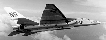
The Vigilante was designed as a Mach 2 carrier-based attack aircraft capable of carrying nuclear or conventional bombs. The airframe has high-set wings sweptback at 37.5 degrees, and sweptback tail surfaces, both horizontal and vertical surfaces consisting of one-piece all-moving surfaces. There are three section spoilers instead of ailerons. Three-section leading-edge flaps are on each wing. There is a flap blowing system for the trailing-edge flaps. The wingtips fold upward, fin-tip sideways and fuselage nose upward for stowage on board ship. The engines are mounted side-by-side in the rear fuselage, with wedge-shape air intakes on each side of the fuselage. A tricycle undercarriage has a single wheel on each unit, the nosewheel retracts inward and mains retract inward.
Two YA3J-1 (NA-233, -247 / 145157/145158) were built, powered by 16150 lb GE YJ79-GE-2. First deliveries were made to the US Navy were made in June 1961 for service trials. They became YA5-A in 1962.
57 production A3J-1 (NA-247, -258, -263, -269, -272) attack aircraft were delivered to the US Navy during 1960, becoming operational on board USS Enterprise in February 1962 (146694/146702, 147850/147863, 148924/148933, 149276/149299). These became A-5A.
A-5A 147856
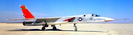
A-5A 147858
In 1962 six A3J-2 (NA-269) were built (149300/149305) with Additional fuel in a humped fuselage-top decking. First flying on 29 April 1962, they became A-5B.
First flying on 30 June 1962, 55 A3J-3P (149306/149317, 150823/150842, 151615/151634, 151726/151728, 156608/156643) were built as a long-range photo-recon version of the A3J-2, plus 59 converted A-5A and A-5B. These became A-5C/RA-5C in 1962.
North American A-5C 156638
North American RA-5C
The other major version of the Vigilante was the RA-5G, a reconnaissance type of which more than 90 were built as new; most of the A-5A were subsequently converted to this standard.
A3J-1 Engines: 2x General Electric J79-GE-2, 10,500 lb (15,000 with reheat) Wingspan: 53 ft Length: 73 ft Height: 20 ft
A3J-1 / A-5A Engines: 2 x J-79, 17000 lb Wingspan: 53’0″ Length: 76’6″ Max speed: 1385 mph Cruise speed: 805 mph Stall: 156 mph Range: 985 mi Ceiling: 43,800′
A3J-3P / A-5C / RA-5C Engines: 2 x J79, 17860 lb Length: 76’6″ Useful load: 42,090 lb Max speed: 1290 mph Cruise speed: 783 mph Stall: 154 mph Range internal fuel: 547 mi Range max fuel: 944 mi Ceiling: 48,400′ Combat radius: 1,500 mi
RA 5C Vigilante Engines: 2 x GE J-79-8(N) turbo-jet, 75.6kN Max take-off weight: 27300 kg / 60187 lb Wingspan: 16.2 m / 53 ft 2 in Length: 22.3 m / 73 ft 2 in Height: 5.9 m / 19 ft 4 in Wing area: 65.0 sq.m / 699.65 sq ft Max. speed: M2+ Ceiling: 18300 m / 60050 ft Range: 3700 km / 2299 miles Crew: 2
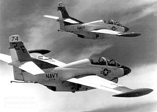
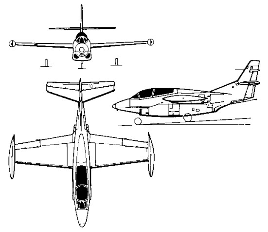
With a requirement in 1956 for a multi-role jet trainer, the US Navy awarded North American a contract to build its North American NA-241 design, which combined proven components and equipment from earlier aircraft manufactured by the company. Ordered as the T2J-1 (later T-2A), this trainer combined a wing derived from the FJ-1 Fury and the control system of the T-28C Trojan with a single 1542kg thrust Westinghouse J34-WE-36 turbojet, and accommodated the instructor and pupil in tandem, seated (eventually) on zero-zero ejection seats.
The first of six initial production T-2As was flown on 31 January 1958 and deliveries to the US Navy began in July 1959, by which time the name Buckeye had been allocated to this trainer. Equipping US Navy Training Squadrons VT-4, -7, -9 and -19, a total of 217 T-2As was built.
Two T-2A were modified to serve as YT-2B prototypes, in which the single J34 turbojet was replaced by two 1361kg thrust Pratt & Whitney J60-P-6 turbojets. The first was flown on 30 August 1962, being followed by 97 similar T-2B aircraft , 152382-152391, 152440-152475, 153538-153555, and 155206-155238 (NA-280, -288, -291, -294, -310) from 1962.
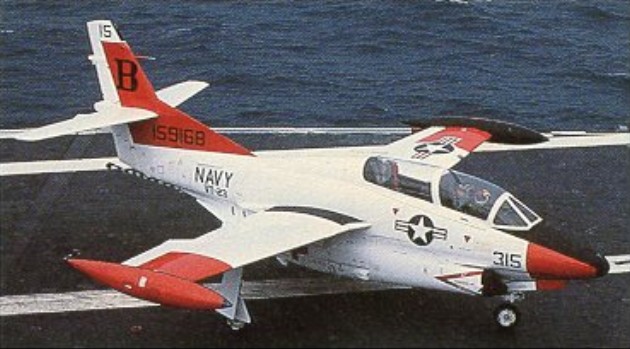
Rockwell-North American T-2B
Final production version was the 1958 T-2C (NA-307, -318, -332, -340) which introduced General Electric J85 turbojets, preceded by a single YT-2C prototype conversion from a T-2B.
A total of 273 was built under US Navy contracts before production ceased, comprising 231 T-2Cs for navy use (155239-155241, 156686-156733, 157030-157065, 158310-158333, 158575-158610, 158876-158911, 159150-159173, 159704-159727) plus 12 T-2D and 30 T-2E aircraft in 1969, procured for Venezuela and Greece respectively.
The DT-2C was a drone director conversion.
It was to be re¬tired in favour of the more advanced T 45 Goshawk which has cockpit instrumentation similar to the F/A-18 Hornet.
T 2A Engine: 1 x 3,400 lbs.t. (1542 kpg) Westinghouse J34 WE 36 Max speed, 492 mph (792 kph) at 25,000 ft (7620 m) Cruise, 422 mph (679 kph) Initial climb, 5,000 fpm (25.4 m/sec) Service ceiling, 42,500 ft (12 950 m) Range, 550 mls (885 km) Empty weight, 6,893 lb (3 127 kg) Loaded weight, 9,916 lb (4498 kg) Span, 36 ft (10.97 m) Length, 38 ft 8 in (11.78 m) Wing area, 255 sq.ft (23.7 sq.m)
T 2B Engines: 2 x 3,000 lbs.t. (1316 kgp) J60. MTOW: 12,300 lb Top speed: 545 mph
YT-2B / T 2B Engines: 2 x J60-P, 3,000 lbs.t. (1316 kgp) Useful load: 3842 lb Speed: 540 mph Ceiling: 44,000 ft
T-2C / DT-2C Engines: 2 x General Electric J85-GE-4 turbo-jet, 13.1kN / 2950 lb Max take-off weight: 5978 kg / 13179 lb Empty weight: 3681 kg / 8115 lb Wingspan: 11.63 m / 38 ft 2 in Length: 11.79 m / 38 ft 8 in Height: 4.51 m / 14 ft 10 in Wing area: 23.70 sq.m / 255.10 sq ft Useful load: 5065 lb Max speed: 521 mph Cruise speed: 465 mph Ceiling: 13535 m / 44400 ft Range: 1465 km / 910 miles Crew: 2
T-2J Engines: 2 x Westinghouse J34, 3400 lb Wingspan: 36’0″ Length: 38’4″ Max speed: 494 mph Cruise speed: 417 mph Stall: 67 mph Range: 967 mi