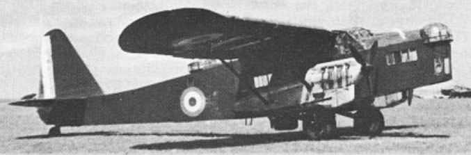
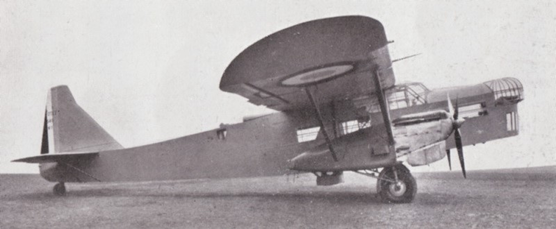
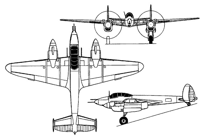
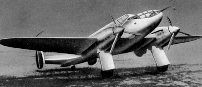
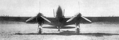
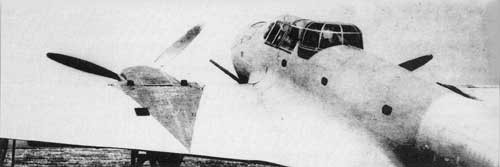
This two-engine aircraft was built as a private venture by the French Potez company to fulfill a 1932 specification for a new reconnaissance bomber. Designed by Louis Coroller, designated the Potez 54, it was intended as a four-seat aircraft capable of performing duties such as bomber, transport and long-range reconnaissance. The Potez 54 was a high-wing monoplane, of mixed wood and metal covering over a steel tube frame. The prototype had twin fins and rudders, and was powered by two 515 kW (690 hp) Hispano-Suiza 12Xbrs V-12 engines in streamlined nacelles, which were connected to the fuselage by stub wings. The main landing gear units retracted into the nacelles, and auxiliary bomb racks were mounted beneath the stub wings. There were manually-operated turrets at the nose and dorsal positions, as well as a semi-retractable dustbin-style ventral turret. The main landing gear units retracted into the nacelles, and bomb racks were mounted beneath the stub wings.
The Potez 54 M.4 category prototype flew for the first time on 14 November 1933 and during development, the original tailplane was replaced by a single fin and rudder, and in this form, the type was re-designated the Potez 540 and delivered to the Armee de I’Air on 25 November 1934.
Parallel with the Potez 540 were developed the Potez 541 prototype, powered by Gnome-Rhone 14Kdrs radials, and the Potez 542 with 537kW Lorraine Petrel engines.
All versions had defensive armament of manually-operated nose and dorsal turrets and a semi-retractable ventral ‘dustbin’ position; radio, oxygen, night and blind flying equipment were standard, and reconnaissance cameras could be carried.
A total of 192 Potez 540s were built.
The French Government declared on 25 July 1936 that it would not send arms to Spain, but its Air Minister, Pierre Cot, secretly permitted a consignment of aircraft to be dispatched. At the end of July, about 70 aircraft were sent across the border to Barcelona, including Potez 54 bombers and Dewoitine 371 fighters.
In early 1938, the Ilmavoimat / Maavoimat test team evaluated the Potez 540. Given the role that the aircraft was expected to fill, the evaluation was cursory and simply confirmed that the aircraft was completely unsuited to the intended role and should not be considered further. In point of fact, the evaluation team were highly annoyed that the French would even put the aircraft forward for consideration given the obvious unsuitability when evaluated against the requirements the Ilmavoimat had provided.
Their first combat was in the Spanish Civil War, where they were employed by the Spanish Republicans. In the late 1930s, these aircraft were becoming obsolete so they were withdrawn from reconnaissance and bombing duties and were relegated to French transport units. They were also employed as paratrooper training and transport aircraft. By September 1939 and the beginning of World War II, they had been largely transferred to the French colonies in North Africa, where they continued to function in transport and paratrooper service. Their role in even these secondary assignments was problematic given their poor defensive armament and vulnerability to modern enemy fighters. Following the French capitulation to Germany in June 1940, those Potez 540s still flying served the Vichy French Air Force mainly in the French overseas colonies. Most of these machines were retired or destroyed by late 1943
Potez 540 Engine: 2 x Hispano-Suiza 12Xirs / Xjrs, 515kW / 690 hp Max take-off weight: 5950 kg / 13118 lb Loaded weight: 3785 kg / 8345 lb Wingspan: 22.1 m / 73 ft 6 in Length: 16.2 m / 53 ft 2 in Height: 3.88 m / 13 ft 9 in Wing area: 76.0 sq.m / 818.06 sq ft Max. speed: 310 km/h / 193 mph Ceiling: 5182 m / 17000 ft Range: 1250 km / 777 miles Armament: 3 x 7.5mm MAC 1934 machine-guns Bomb load: 4 x 225kg or 10 x 55kg Crew: 4-7
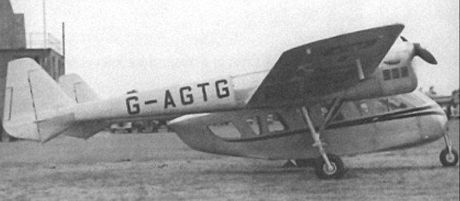
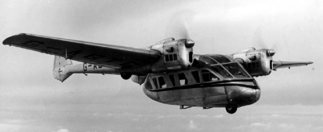
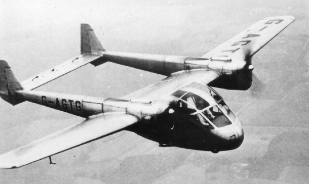
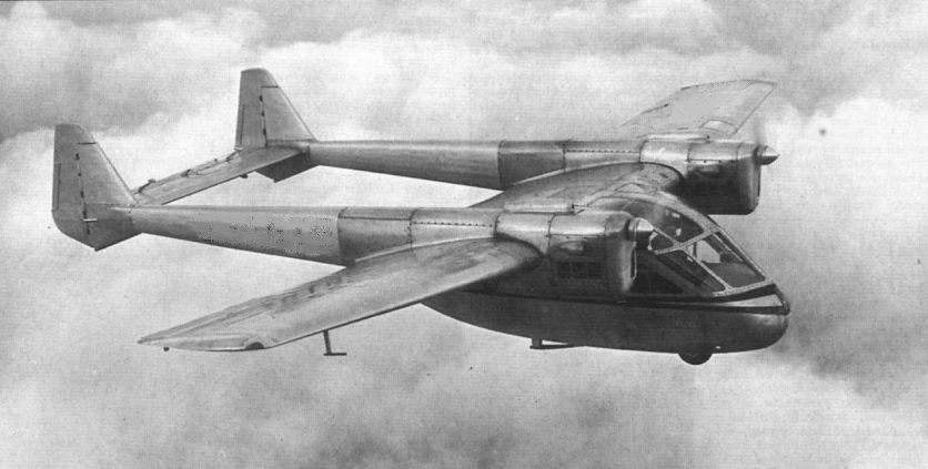
The prototype Portsmouth Aerocar Major G-AGTG was flown on June 18, 1947 when it was exhibited at the1947 SBAC Show held at Radlett, UK.
It was powered by two Blackburn Cirrus Major Series III engines of 155hp each. The retractable undrcarriage was pneumatically operated, and the manufacturer envisioned both ski and float versions as well. The pod and boom layout and its multi-role capability attracted much interest, despite the fact that the prototype was somewhat under powered or over weight. But after a promising start, financial backing for full development and production was not forthcoming, and by the latter part of 1948 the Aerocar project was abandoned following re-structuring of the Portsmouth Aviation Company. It was scrapped in 1950.
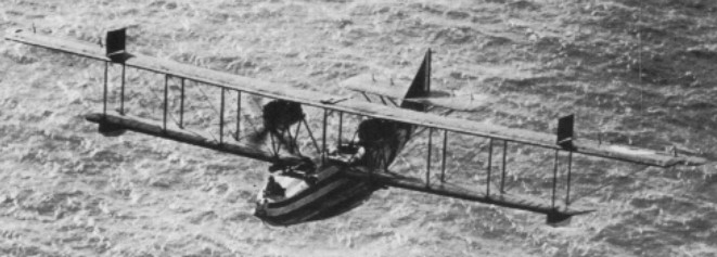
The Admiralty placed orders for Curtiss H.4 and H.12 flying-boats in 1924-15 on the recommendation of Squadron Commander John Porte. When they arrived, Porte fitted some with much improved hulls of his own design, built at the Naval Air Station of Felixstowe and by private manufacturers.
The engines were also replaced by Rolls-Royce Eagles in the H.12’s, which were redesignated F.2A.
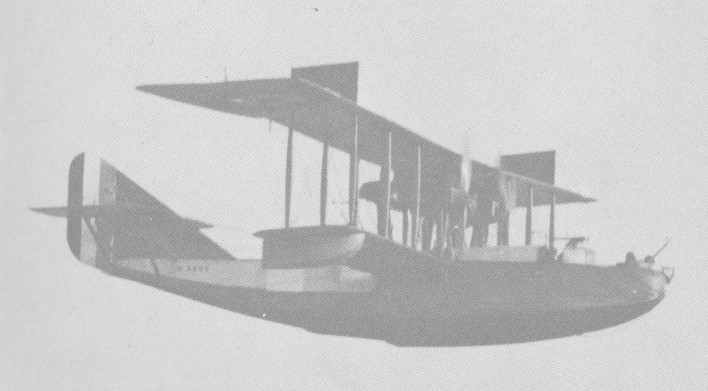
They featured three-bay biplane wings with two spar wood construction and fabric covering. The hull was wood with plywood covering. Conventional controls with ailerons on the top wings only. Stabilising floats were under each lower wing tip.
Normal defensive armament was four Lewis machine guns: one in the nose cockpit, one in the rear cockpit aft of the wings and one on each side of the fuselage. Sometimes the nose and rear positions were each fitted with two guns, and an additional gun could be mounted above the pilots’ canopy. Racks for two 230-lb bombs were under the wings.
Best known was the F.2A, which, in the last year of the war, formed the backbone of RNAS/RAF ocean activ¬ity. Carrying up to seven Lewis guns and two 220 lb bombs, it had a maximum weight of 11,000 lb, its two 345 hp Rolls¬Royce Eagles gave it a top speed of 95 mph and it could reach 2,000ft in 3.5min and 10,000ft in 39.5min. Despite its 120ft wingspan it was surprisingly agile. Gradually F.2s replaced H12s.
The F2A was basically a Porte II hull married to the wings and tail unit of the Curtiss H.12. Utilised by Britain during WW 1 and credited with shooting down Zeppelins L.22, L.43 and L.62.
F.2A Engines: 2 x Rolls-Royce Eagle VIII, 345 hp Propeller: 4 blade Wingspan: 95 ft 7.5 in Wing area: 1133 sq,ft Length: 46 ft 3 in Height: 17 ft 6 in Empty weight: 7549 lb MTOW: 10,978 lb Max speed: 95 mph at 2000 ft Service ceiling: 9600 ft Endurance: 6 hr Armament: 4-7 Lewis machine guns Bombload: 2 x 230 lb
By July 1916 first examples of a larger Curtiss flying boat design began arriving in England. Designated H.8, these were quickly modified to accept more powerful twin 250 hp Rolls Royce engines, and redesignated Curtiss H.12s, or ‘Large Americas’ as the RNAS crews usually referred to them. The Curtiss H.12 hull soon proved to be inadequate for its tasks, so Porte designed a new hull (the Porte II), resulting in all round improvement in performance. With a new tail unit added, the modified craft was designated Felixstowe F.2, and its general structure became a prototype for succeeding F boats.
Large scale production of the F.2 was ordered, and the type began to equip RNAS units in late 1917. Carrying a crew of four, and a bombload of approximately 272 kg (600 lb), the F.2a (its production designation) could achieve a maximum speed of some 145 km/h (90 mph), with an endurance of perhaps six hours. It was cumbersome to handle and slow in manoeuvre, yet gave formidable operational service for the rest of the war. With at least four machine guns in nose, tail, and flank locations, it also gave a good account of itself when engaged by German seaplanes. The F.2a’s main duty was antisubmarine hunting; an air deterrent which undoubtedly proved successful in the protection of Britain’s vital mercantile shipping.
Span: 29 m (95 ft 7.5 in) (upper), 20.8 m (68 ft 5 in) (lower) Length: 14.1 m (46 ft 3in) Height: 5.3 m (17 ft 6 in) Maximum speed: 153.7 km/h (95.5 mph) at 609.5 m (2000 ft)
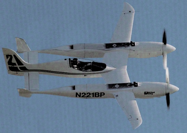
In 1988 Robert Pond (who derives a comfortable income from the manufacture of floor-cleaning products) contracted Burt Rutan’s Mojave, California, Scaled Composites, for the design and production of a prototype new-generation racing plane. Scaled engaged Nissan subsidiary Electramotive, a motorsport engine developer in Vista, California, to provide engines and gearboxes for the airplane. Rutan wanted to keep his pilot away from fuel, oil and hot coolant which meant a fuselage separate from the engine nacelles. The weight of the pilot’s pod is low, since it is supported at both ends and serves no structural purpose other than to hold up the pilot. The interference drag between the wing and the pod is nil. But most important, the pilot is as far away as he can be from the hazards of the powerplants. The airplane’s structure is mostly of graphite composites, often in the form of a sandwich with plastic foam cores. A special epoxy is used for compatibility with the engines’ methanol fuel. Despite its tiny size – 25-foot span and 20-foot length—and advanced materials, the Pond Racer is a dense little airplane, weighing 4,500 pounds ready to fly. Its useful load is only 650 pounds.
Liquid-cooled, with a single overhead cam, two valves per cylinder, and 3.2-liter (200-cubic-inch) displacement, the Electramotive VG30 engines are based on the Nissan V-6 block used in the 300ZX and Maxima automobiles. Though their blocks are very compact, the engines use up a lot of space once the turbochargers and radiators and associated ducting are included (in fact, the complete installed powerplant weighs around 700 pounds versus 350 for the basic engine). They are packed incredibly tightly into the two-foot-diameter, five-foot-long nacelles. The engines are mounted solidly to the airframe and the cowling skins are a load-bearing part of the engine mount, permitting the gap between spinner and cowling to be little more than a knife-slit. More than a year was spent developing a gearbox to bring the engine’s 8,000-rpm operating speed down to a propeller-friendly 2,000.
The engines are electronically controlled. There are manual backups, but normally the throttle and prop controls move potentiometers, whose signals arrive, digitized, at each engine’s two Intel microcontroller chips along with temperature and pressure data from almost two dozen other sources. The microcontrollers consult schedules containing the desired boost and the duration and timing for the spark and injection, and adjust those parameters for each power stroke.
At the same time, airframe and powerplant data are recorded every two seconds, and can be dumped at the end of each flight to a computer and instantly displayed in graphical form. Technicians can then use the data drawn from each run to modify the laws governing engine operation until the optimum is achieved.
To deliver 1,000 hp, the engines must be boosted to 110 in. Hg and turn at 8,000 rpm. They must run continuously at that setting for the 15 minutes of a race, although they never gave more than about 600hp.
On March 22, 1991, the first flight was described as a “no-brainer”. It took several flights to get the engines working well at moderate power, and even late in August they were still chronically misfiring and undergoing constant readjustment. One source of difficulty is that the engine control computers don’t monitor one variable important to airplanes though not to race cars: air density. With a wing loading of over 70 psf, touchdown is at a hot 120 knots.
The original intention had been to remove some or all of the angled “butterflies” at the tips of the horizontal stabilizer after flight-test demonstrated sufficient directional stability. Now they may be moved to a horizontal position instead, since the airplane has so little static margin that it requires no trimming between 140 and 250 knots.
A major source of trouble during testing has been the methanol fuel. Not a petroleum product, methanol, like alcohol, is derived from plant fermentation. It has about half the specific impulse of gasoline, which means that twice as much of it must be burned to produce a given amount of power. But it also burns over a far wider range of mixtures, so that engine cooling can be supplemented simply by pumping a lot of excess methanol through the engine. What doesn’t burn in the cylinders emerges from the exhaust pipes as a roaring plume of flame familiar to drag-race buffs. Methanol also doesn’t detonate, and that is what allows it to run at the astronomical levels of boost necessary to pull 1,000 hp out of an engine having fewer cubic inches than that of a Cessna 152. Methanol has very unfriendly relations with many materials. “It eats us alive,” Dick Rutan says. After repeated episodes of corrosion and oil contamination, it became standard operating procedure to drain the fuel systems after each flight and refill them with aviation gasoline in order to protect components from the methanol. Even if Burt Rutan scored a bull’s-eye in flying qualities, there are still other major uncertainties waiting to be resolved. One is the reliability of the engines while being operated continuously at 1,000 hp. Another is handling qualities at top speed; because the engines can’t be opened up, the Racer has not yet been flown above 333 KIAS (357 knots true airspeed). Yet another unknown is the efficiency of the propellers. Four-blade and 80 inches in diameter, they are King Air props modified by Hartzell to specifications developed by John Roncz, a longtime consultant of Rutan’s who also designed the wing and tail airfoils for the Racer. Their knife-thin tips are designed to run at 98 percent of the speed of sound—not a regime in which propellers are routinely used. The other question mark is airframe drag. Although the Racer is small, it is complex in shape, with many intersections and much internal cooling flow whose drag is difficult to estimate. At 460 knots, air will slam into it like cinder blocks, with a force of 600 pounds per square foot. At that speed a small surplus of drag could mean the difference between success and failure for the whole project.
Its bulky fuel load notwithstanding, the Pond Racer turned out to be a tiny airplane only 20 feet long, with a wing span of slightly more than 25 feet. It weighs 4,000 pounds when fully fueled. Scaled Composites, Rutan’s company in Mojave, Calif., finished the racer’s airframe in June 1989, but the engines and gearboxes took another year and a half to be completed. During that time the Rare Bear pushed the official speed record to 528 mph one mph faster than Rutan’s hoped for top speed.
At Reno 1991, a connecting rod punched through the left engine’s oil pan, dumping lubricant on the hot exhaust pipes and causing a fire. Race pilot Rick Brickert triggered the Pond Racer’s Halon fire extinguishing system, which smothered the blaze, then flew the craft to a one engine landing. After Reno, the racer was transferred from Mojave to Pond’s home airport at Palm Springs, Calif., to await further development.
N221BP appeared at Reno in 1991-93, qualified at 400mph.
Destroyed in a forced landing crash in 9/14/93, killing pilot Rick Brickert.
Engines: 2 x Electromotive-Nissan VG-30 GTP, 600 hp Wingspan: 25’5″ Length: 20’0″ Useful load: 640 lb
About 1997, Marvin Polzien decided he wanted a homebuilt blimp. There were no quick-build kits for homebuilt blimps, set of plans and a kit of materials for a homebuilt blimp. Marvin, along with friends Dennis Riley and Louie Remondino, decided to design their own. Marvin subleased part of a large military hangar on the Ardmore airport, Oklahoma, and the work began, with other volunteers pitching in.
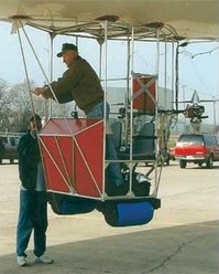
Their first model was a cylindrical bag of aluminized plastic attached along the bottom to a welded-aluminum truss structure. A simple platform suspended from the truss provided a place for the pilot to sit (in a plastic patio chair) and a place to mount the power unit (a hot-air balloon inflator fan). About that model, Marvin says, “It was a total disaster– the material we used was no good – it leaked like a sieve. We took it out of the hanger once and I made one tethered trip around the ramp, but that was all. Then we deflated it and put it away.”
Using lessons learned from the first model, the team designed the second model. He says, “We just made it up as we went– we didn’t know what we were doing. Our learning curve was pretty wide, so we’ve got a lot of junk lying around that didn’t work.”
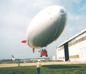
The first step was to select a better material for the envelope. Helium is a small molecule that can sneak its way through most materials, so low permeability was a primary requirement. They selected a .009”-thick white heat-sealable polyester plastic with good tear resistance.
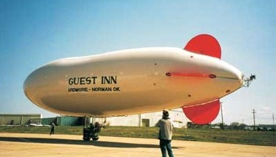
To achieve the desired buoyancy, they decided to make the envelope 82 feet long and 20 feet in diameter, tapered to form a streamlined nose and tail– an estimated 18,000 cu. ft. capacity. A two-place welded-aluminum “car” for a pilot and passenger would be supported from the bottom of the envelope, supported by a “catenary curtain” of suspension lines inside the balloon.
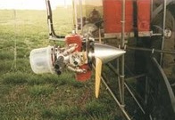
A 12-hp engine/propeller unit mounted on each side of the car would provide the main power. Each engine would be able to tilt up or down to vector thrust for climbing, cruising, or descending.
Pitch and yaw control would be provided by a third engine/propeller unit (24-hp) mounted on a gimbal at the extreme rear of the envelope and controlled from a control stick in the car. Fixed horizontal and vertical stabilizer panels would augment pitch and directional stability.
Inside the envelope would be two “balloonets” – smaller bags inside the large bag immediately forward and aft of the car– that could have air pumped in or out for trim control. Air would be provided from a compressor mounted on one of the engines.
A total of 13 gores of the 60” polyester would be required for the 20-ft diameter. In January 2002, the team laid out the gores on the hangar floor and cut them out. Then they began the monumental task of lapping and heat-sealing the gores together to form the envelope.
In February 2001, the envelope was fully sealed. After a preliminary filling with air (supplied ingeniously by a Shop Vac), the first filling with helium was an adventure. “We tried to fill from the middle first, but suddenly the helium all shifted to the front of the bag and up it went into the rafters! We were lucky we didn’t damage it. Now, we put sandbags across the envelope and fill from the back first. As it fills, the sandbags gradually roll toward the front,” Marvin said.
Of course, with the opportunity to fill with helium comes the necessity to empty it out now and then. But how does one keep from losing $1700 worth of helium? “Simple,” says Marvin, “We just built another storage bag bigger than the envelope and transferred it over!” But, how? “Shop Vac,” he says matter-of-factly. Marvin is a true innovator.
By March, the blimp had been taken outside for its first tethered flight. Finally, on August 3, 2002, the first free flight was accomplished. Watching video of the takeoff, Marvin said, “At that point, I didn’t know doodly about flying that blimp.”
After a short trip around the airport at about 200 feet at what appears to be about 30 mph, the video shows him approaching to land. He continued narrating, “About that time, I was asking myself how I was gonna land! I decided to rotate the engines down to pull me downward, but now I know I can just point the nose down a little to descend.”
Since then, Marvin has flown the blimp “five or six more times– I lose count.” On one flight he had an engine failure and, while trying to restart it, allowed the blimp to drift into some trees, punching a few holes in the envelope.
He has lost the lease on the big hangar and expects to be kicked out at any time. “I don’t know,” he says, “Sooner or later, I’ll have to deflate it, pack it up, and put it in my hangar.”
In December 2009 hundreds watched as a blimp piloted by 79-year-old Marvin Polzien flip flopped across the sky over Ardmore. He says he brought the blimp down near the freeway because a motor that helps steer the blimp failed. “I had three alternatives on how to land that thing. One was in the trees- that was not an option. Next one was in the median on the interstate, which is not good, and the third option which is to just take it up and let the wind blow me northwest of Ardmore,” Polzein said Thursday.
After the members of the FAA showed up wanting to see Polzien’s pilot’s license and medical certificate, which he couldn’t produce, his blimp could be grounded be for good. In order to operate an airship, it must first be certified with the FAA and its operator must have at least a private pilot’s license.
Also working against him is that fact this is not the first time he’s had to make an unscheduled landing. He crashed another home made blimp last May. That same blimp also floated away the next day and managed to make it all the way to North Texas with no one in it.
In March 1919 Polikarpov was selected as head of the technical department of the former Duks factory, soon to be renamed State Aviation Factory No.1 or GAZ No.1. In 1920, the first Soviet aircraft would be projected and built in GAZ No.1 and just three years later, it would already plan the construction of a multi-engine military aircraft known as 2B-L1 and powered by two 400 hp Liberty engines.
Nikolai Polikarpov’s construction activity was generally linked to fighters, but Polikarpov’s beginnings in aviation were directly linked to the Ilya Múromets bombers designed by Igor Sikorsky.
The development of this bomber began at GAZ No.1 in 1924 and the project was led by engineer L. D. Kolpakov-Miroshnichenko. Polikarpov had no relationship with the development of this project, since with the arrival of D. P. Grigorovich he would be excluded from the factory and transferred to the Glavnoavia aeronautical construction department. However, by the fall of that same year, after Grigorovich’s departure, Polikarpov would return to GAZ No.1 as head of the construction bureau. Once in this position he refused to take part in the construction of the 2B-L1 and acting as a consultant, he basically became a critic of the bomber.
The plane, however, began to be built. The VVS, foreseeing the possibility of practical use of the model, decided to replace the designation 2B-L1 with B-1, but it would soon become clear that the new bomber did not satisfy many of the requirements imposed by the military. This was the main reason why, even without finishing the B-1, it was decided to start working on a new bomber, which was called the B-2.
According to the requirements issued by the VVS management, the new bomber had to incorporate 3 to 4 Liberty engines. The B-2 should lift a weight of 1000 kg with an average speed of 170 km/h and transport it over a distance of 1000 km.
To meet this new requirement, the GAZ No.1 construction bureau developed six possible bomber variants:
4B-L3 – biplane with 4 Liberty engines and takeoff weight of 9 tons;
4B-L3 – biplane with 4 Liberty engines and takeoff weight of 10 tons;
4B-L3 – sesquiplane with 4 Liberty engines and takeoff weight of 11 tons;
3B-L3 – sesquiplane with 3 Liberty engines and takeoff weight of 9 tons;
3B-L3 – monoplane with 3 Liberty engines and takeoff weight of 8-9 tons;
4B-L3 – monoplane with 4 Liberty engines and takeoff weight of 10 tons.
Within this list were included projects by Polikarpov, Kolpakov-Miroshnichenko and Krylov.
Interest in these works remained between July and October 1925, but by this date it had already been decided to abandon the option of the Liberty engine, considering it lacking in perspective and to redesign the bombers with two 600-hp Wright Tornado North American engines.
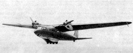
As a basis for this new design, it was decided to use the French Farman Goliath bomber. Several of these aircraft had been acquired and arrived in Leningrad at the beginning of October.
To evaluate this foreign bomber and become familiar with its assembly, it was decided to send a group of specialists from GAZ No.1 to Leningrad. Polikarpov managed to ensure that neither Kolpakov-Miroshnichenko nor Krylov were included in this group, leaving the competition aside.
Already in the autumn of 1924 Polikarpov, head of the construction bureau and later head of the experimental department, had managed to establish a new, more effective system of work organization. The main objective of this new system was destined to gradually relegate the work of the old engineer-builders, accustomed to developing, approving and building their models based on their customs and points of view. The new structure of the OKB planned to use a system similar to the one adopted by A. N. Tupolev at the TsAGI, where a group of engineers defined the general concepts and then the different departments worked on the development of the components and systems.
The new B-2 bomber with two Wright Tornado engines, in its development stage began to be called GAZ No.1 2B-R2. The project began development in the spring of 1926.
Because the Wright Tornado engine had to be used in other types of devices, the possibility of buying a certain amount and then copying the model was valued, in the same way that this had been achieved with the Liberty.
The 2B-R2 was designed as a twin-engine biplane of mixed construction and was characterized by its bi-derived tail with double horizontal planes. The landing gear was of the conventional and fixed type.
Despite the great projection work carried out and the progress in the work, in April 1926 it was decided to cancel the VVS request for the 2B-R2 bomber. The main reason was the appearance of the all-metal Tupolev ANT-4 bomber, developed at TsAGI at the request of the Ostiexbyuró. The VVS management, pleased with the results of this new model, otherwise quite superior to the 2B-2R, decided to introduce it into service with the designation TB-1.
After a year and the appearance of some problems in the development of the TB-1 due to the lack of practice in the use of metal construction, it was decided to develop an alternative version of mixed construction. This job was assigned to Polikarpov’s collective and would be the basis for the TB-2 bomber.
2B-R2 Engines: Two 600 hp Wright Tornado Empty weight: 5200 kg Maximum takeoff weight: 9150 kg Payload: 3950 kg Maximum speed: 180 km/h Practical ceiling: 4000 m Bombload: 1500 kg Accommodation: 5
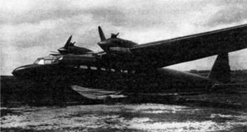
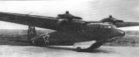
The excellent results obtained during Aeroflot’s experimental use of the BDP-2 prototype as cargo transport made Polikarpov think about the possibility of developing a motorized model, especially that there was talk of the possibility of producing a small series.
To achieve this goal, two cowled 145 hp M-11F engines were installed on the wing leading edge. The new model was called MP (Russian: Поликарпов М П), short for Motoplanior (motor glider).
In the MP operation, the autonomous take-off variant was envisaged, but with the full load capacity the low power of the engines was unable to guarantee take-off. Generally, the MP had to take off and even arrive at the site of operations dragged by a tow plane, but after dropping its load, unlike conventional gliders, it could return to its airfield using the installed motive power.
As a small capacity transport aircraft, the MP could carry 12 equipped soldiers or a similar weight capacity.
The MP motor glider generally maintained the constructive characteristics of the BDP glider. It was designed as a monoplane with a high wing of 20 meters of wingspan and a fuselage with an aerodynamic design. The entire construction was made of wood.
The fuselage was entirely made of wood and featured monocoque construction.
The exit of personnel and cargo was carried out through two doors of 860 x 900 and 850 x 950 mm, one located in the front region on the right and the other in the rear on the left. In the lower part of the fuselage, behind the cargo area, a hatch was prepared to leave the parachute glider.
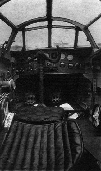
The pilot had an emergency cover with a structure also in wood. To improve visibility during landing, the lower area of the cabin was glazed. People sat on benches located on the sides of the glider, attached to the fuselage frame. Between the two benches there was a 600 mm wide corridor.
The wing of the BDP was made of wood and featured a double-spar centre and single-spar consoles. The coating of the leading edge and the force points was done with plywood. The rest of the wing was covered with fabric. The wing profile used was the NACA 230. In order to reduce the landing speed in the section between the ailerons and the fuselage, Shrenk-type flaps were installed.
The tail was monoplane and cantilever, constructed of wood covered with plywood and fabric.
The landing gear on this model was modified with the addition of wheels to the basic glider ski gear. These wheels were installed in two rows under the fuselage and featured rubber cushioning.
The powerplant consisted of two 145-hp M-111M-11F engines located on the wing leading edge and cowled, moving 2.35-meter propellers from Polikarpov U-2 training aircraft. The fuel capacity allowed for 7 hours.
The glider did not have its own weapons, but did have attachment points for seven DP-type infantry machine guns. Two machine guns could be installed in special hatches located in the area of the leading and exit edges of the wing to defend the upper hemisphere. To defend the tail a section of the upper rear fuselage could be raised and become a firing point for the gunner. Two other positions were located to the sides.
Inside the fuselage were 12 5.5 mm armored plates of 480 x 550 mm. The pilot had armor on the back of the seat. All this armor added 127 kg to the weight of the glider.
The motor glider was built ay the Novosibirsk Factory No.51 in the summer of 1943. The acceptance tests were carried out at the Moscow Central Airfield with flights to the Air Landing Forces (VDV) airfield at Medvied Lake and to the LII airfield in Ramenskoye. These flights were developed by the chief of flights and test pilot of the OIAE VDV Captain SA Anojin.
Between July 12 and September 10 of 1943 70 flights with a total duration of 40 hours and 10 min were performed. In flights towed by an SB bomber, heights of 4500 meters and speeds of 270 km / h were reached.
As a conclusion of the tests the pilots VN Yuganov, VL Rastorguyev, GM Shiyanov, AN Grinchik, PF Fedrova, PM Stefanovski, VV Shevchenko, AK Dolgov, PG Savtsov, Gavrilov, Romanov and Borodin wrote that the MP had good stability, it was simple in the piloting, accessible to pilots of low qualification. With a single engine and a flight weight of 3000 kg the aircraft was easily controllable, keeping its flight horizontal and responding to turns.
Between September 10 and 13, 1943 the MP was tested by the VDVs. Load tests were carried out with 4000 kg in different variants: 11 armed infantry soldiers with light weapons; A group of anti-tank artillery made up of 6 soldiers with a 45 mm piece and two shell boxes (40 units). Assembly of the barrel to its operational state took 8-10 minutes; A DShK antiaircraft battery with its 5 servers and ammunition; A light anti-tank group with 10 soldiers and three anti-tank weapons; Two or three motorcycles (3 of the Velosiet type or 2 Indiana).
The excellent layout of the motor glider for these configurations was highlighted and its use was recommended for VDV units and transport aviation. Series production of the model was also proposed.
Despite these results, the MP was never produced. By that time the Red Army had liberated a large part of the territory occupied by the Germans and the supply needs of the guerrilla groups had diminished.
Only the prototype was produced.
Polikarpov MP Engines: Two 145 hp M-11F Wingspan: 20.00 m Wing area: 44.72 m² Length: 13.60 m Height: 3.20 m Empty weight: 2420 kg Normal loaded weight: 3500 kg Payload capacity: 1280 kg Wing loading: 78.5 kg / m² Maximum speed at sea level: 185 km / h Maximum speed at 1000 m: 179 km / h Range: 390 – 700 km Endurance: 7 h Time to 1000 m: 12.5 min Service ceiling: 2,700 m Take-off run with 3500 kg: 480 m Crew: 1
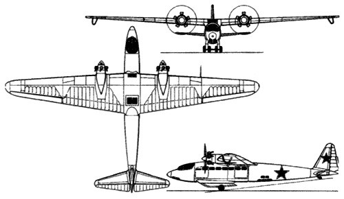
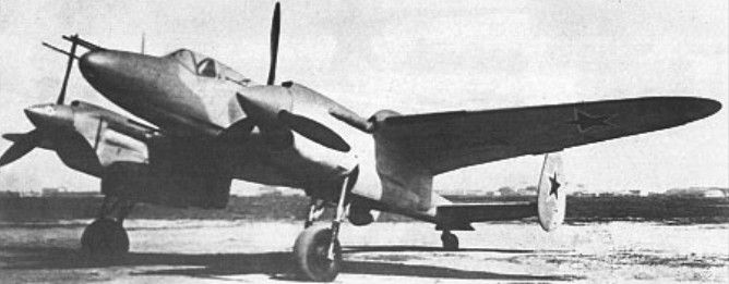
To meet a requirement for a heavy escort fighter, or TIS (Tyazhely istrebitel soprovozhdeniya), formulated in the autumn of 1938, the Polikarpov OKB designed a low-wing monoplane of all-metal construction powered by two 1,400hp Mikulin AM-37 engines. Fixed forward-firing armament comprised four 7.62mm and two 20mm guns, rear protection being provided by single flexible 7.62mm guns fired from dorsal and ventral positions by the second crew member. The first prototype, Samolet A, was flown in September 1941, but evacuation of the Polikarpov facilities to Novosibirsk delayed the programme, and an improved second prototype, Samolet MA, was not flown until 13 June 1944. The MA was intended to be powered by 1,700hp Mikulin AM-39 engines, but their non-availability dictated installation of 1,665hp AM-38 engines. Fixed forward-firing armament was changed to two 37mm cannon and two 12.7mm machine guns. The flight testing of the MA was in its early stages when, on 30 July 1944, Polikarpov died and his OKB was almost immediately disbanded, the TIS programme being abandoned.
Max take-off weight: 7840 kg / 17284 lb Empty weight: 5800 kg / 12787 lb Wingspan: 15.50 m / 51 ft 10 in Length: 11.70 m / 38 ft 5 in Height: 4.35 m / 14 ft 3 in Wing area: 34.85 sq.m / 375.12 sq ft Max. speed: 555 km/h / 345 mph Range: 1070 km / 665 miles
The first reference to a Polikarpov twin-engine model capable of executing bomber actions comes from the first half of 1936. This sketch would originally receive the name VT or Vozduzhni Tank (Flying Tank), which would later become MPI (Mnogomiestni Puchechni Isterbitiel or Multiseat Gunship Fighter) and SVB (Samoliot Vozduzhnovo Buoy or Air Combat Plane).
At the beginning of February, at one of the government meetings, Polikarpov learned that the OKB-2 collective, under the direction of Shpitalni, had developed a powerful 37 mm automatic cannon with a high muzzle velocity. Unfortunately, this weapon had not been tested due to the absence of an aircraft capable of using it.
In turn, Polikarpov reported that his group had developed a development of the TsKB-44 model with excellent technical specifications that could be ideally used as an aerial gunship intended to combat armored formations.
In this way, the idea of creating the new model according to Shpitalni himself constituted “…the synthesis of the achievements of the OKB-2 in automatic weapons, Polikarpov ‘s research in aviation aerodynamics and Polikarpov’s group of colleagues in the direction of automatic weapons”.
Shortly after this meeting, at Factory No.39 Polikarpov would develop three versions of the new aircraft that Polikarpov began to call VIT (Vozduzhni Isterbitiel Tankov or Aerial Tank Fighter (Russian: Поликарпов ВИТ-1)). Unfortunately, Factory No.39 soon began producing the DB-3 bomber and Polikarpov with his group was transferred to Factory No.21. This fact, together with the non-inclusion of these works in the experimental construction plan, led to the closure of work on the VIT as of July 5, 1936.
Faced with this situation, Shpitalni, at the beginning of 1936, sent a document to the secretary of the STO before the SNK USSR, GD Basilievich, in which he requested authorization to build the new VIT model in Factory No.22. This document was accompanied by M-100- powered and M-34FRN- powered VIT variants. The conceptual ideas were signed by Locev (drawings), Sigayev (brigade head) and Polikarpov (constructor). The designs were also signed by Shpitalni.
This model was presented as an all-metal monoplane with a low wing and a twin-engine power plant, with excellent aerodynamic shapes. On both sides of the fuselage were located the two 37 mm cannons with a total reserve of 100 projectiles. The magazines with 5 projectiles each were located in an elevator powered by an electrical system.
In the bow area, in front of the pilot, there was a fixed 20 mm ShVAK cannon with 100 – 200 projectiles and a belt feed. A ShKAS machine gun with 540 rounds was located in the gunner’s cabin to defend the rear hemisphere. This machine gun was installed on a mobile mount that guaranteed firing to the right or left.
The gunner’s cockpit had a glass cover that could be raised above the fuselage, which guaranteed a shooting angle of 65º upwards, 15º downwards and 45º horizontally to the sides.
The model was capable of carrying 200 kg (2 FAB-100 or 20 AO-10 bombs). In case of elimination of the 37 mm guns, the bomb load reached 1000 kg (2 FAB-500 or 4 FAB-250).
In the descriptive memory it was explained: “ – To judge the power of this aircraft it is enough to say, for example, that only the power of the weapons installed in the nose exceeds by more than 10 times the firepower of the most powerful fighter in service with our VVS. … To date, neither in the USSR nor in foreign armies there is a combat vehicle designed for active action against large groups of tanks. “This task is solved by our aerial tank fighter (VIT).”
The reaction to this Shpitalni document was instantaneous. State funding was provided and a resolution was prepared to include the model in the experimental construction plan.
On the other hand, the basis for production in Factory No.22 was not delivered. In its place for the development of the VIT at the end of August 1936 Factory No.84 in Khimki was made available. This factory, formerly part of the civil aviation scheme, had outdated equipment and lacked qualified personnel. Under these conditions, construction work on Polikarpov ‘s two-seat anti-tank aircraft began.
Unfortunately, the idea of this type of aircraft did not find the necessary support within military circles at that time.
It is noteworthy that from its conception the VIT was conceived as a technological demonstrator designed to study construction and technological methods. On its basis, a family of seven aircraft models with different tasks would be developed, capable of sharing a large percentage of common elements. This family included:
– Fast medium bomber with capacity for 800 kg of bombs inside the fuselage;
– Dive bomber with 900 kg of bombs on external supports;
– Long-range reconnaissance aircraft with a powerful armament of 4 20 mm cannons;
– Ground attack aircraft armed with six cannons, two machine guns and 300 kg of bombs;
– Fighter for large ground targets with two K-37 guns and two ShVAK;
– Escort aircraft for heavy bombers;
– Naval aircraft with floats with torpedo boat capacity.
By the end of 1936, the plans for the SVB version (Skorostnoi Visotni Bombardirovchik or High Altitude Fast Bomber) were practically finished. The word “visotni” represented a trend of the time, but in reality the model lacked a sealed cabin and turbochargers for high-altitude operations. In practice it was simply a high-speed medium bomber.
Based on this model, the plans for the model armed with VIT-1 2M-103 cannons would be developed. It is noteworthy that the “VIT” stamp appears on most of the SVB plans, but in that same period new plans were designed for the new model.
As weapons for destroying tanks, the use of two 37 mm ShFK-37 cannons of the OKB-15 NKV (as the Shpitalni construction bureau was now called) located in the wing roots was maintained. The name of these guns comes from the acronym Shpitalnovo Fyuselyazhno-krylevaya Pushka or Shpitalni Wing and Fuselage Gun.
Polikarpov presented the design of the aircraft in two variants: multiseat gunfighter or MPI and anti-tank aircraft or VIT. On January 31, 1937 the evaluation commission reviewed the model of the MPI-1 version with two M-103 engines and on July 25, by government decision, the experimental construction plan was approved for the current year in which it was considered. the construction of two examples of the multiseat gunfighter with two M-103 960 hp engines with a maximum flight speed of 500 – 550 km at an altitude of 5000 meters.
The VIT-1 was designed as a low-wing two-seat monoplane with beautiful aerodynamic shapes and smooth skin on a thin fuselage. The landing gear was of a retractable type and a monoplane tail with a single empennage.
The fuselage, built entirely of metal, had an oval cross section. The construction was semi-monocoque.
The central section constituted a combination of closed duralumin profiles and skeletal structures of welded steel tubes.
The wing, with a double spar, had a trapezoidal shape in the plane with rounded ends and ended at the junction with the fuselage, presenting the characteristic extensions of many Polikarpov models. The wing profile used was the Clark Y with a relative thickness of 14% at the root and 6.35% at the ends.
The wing spars were constructed of welded chrome-molybdenum steel tubes. The ribs were built with duralumin profiles, except for the engine area, where they were replaced by welded steel tubes. The ailerons featured aerodynamic and weight compensation.
The tail section was all metal. The stabilizer was fixed to the fuselage structure. The empennage was constructed of duralumin.
The entire cell was calculated according to resistance standards for fighters, supporting overloads of up to 13g.
The landing gear was of the conventional tailwheel type. The landers with the wheels were retracted backwards, inserting into the lower area of the power nacelles. The retraction system was pneumatic. The main wheels had brakes. The tail wheel was not retractable.
The 860 hp M-103 engines were selected as the power plant. The composition of the cooling radiators was somewhat unusual for a twin-engine aircraft. The radiators were located in retractable structures equipped with tunnels for the entry of air. These structures were located on the wing extrados on the outer sides of the power nacelles and depending on the flight regime, they extended or were practically hidden in the wing. Control was carried out with the help of a thermostat.
The VIT-1’s armament was the most powerful installed on any Soviet fighter up to that time and consisted of two 37 mm ShFK-37 cannons located in the wing roots.
The defensive armament consisted of a TUR-10 turret with a ShKAS machine gun on the rear fuselage, which would later be replaced by one of the SUDB-3 type, similar to that used in the Ilyushin DB-3 bomber, which was produced in the Factory No. 32.
The normal bomb capacity reached 600 kg on internal supports and up to 1000 kg of bombs (two FAB-500) could be installed outside.
The crew was made up of two people: pilot and gunner. Both crew members were located in a cabin on the wing spars. No shielding was provided.
On October 14, 1937, the assembly of the first flying example of the MPI-1 gunfighter was completed. The prototype was built in the Moscow factory No.84, where Polikarpov had been transferred with his team in the second half of 1936. Some time later this would begin to be called VIT-1 (Vozduzhni Isterbitiel Tankov or Aerial Tank Fighter No.1). This would be the definitive name used from now on to refer to the plane.
The first flight with Valeri Pavlovich Chkalov at the controls took place on October 31. On November 16, during the third test flight, the navigator’s cockpit would be occupied by designer Nikolai Polikarpov.
The VIT managed to reach a fairly high maximum speed for its time, of 494 km/h at 3000 meters altitude. The range recorded at 90% of maximum speed was about 1000 km.
The factory tests, carried out until February 1938, would never be completed due to the impossibility of achieving the specified performance. The plane did not manage to exceed 500 km/h and some problems related to longitudinal and transverse stability were evident.
Despite this, the model proved to have development prospects and only the lack of support from the GUAP prevented its presentation to the state acceptance tests. The VIT-1 incorporated powerful weapons for the time: two 37 mm ShFK-37 (K-37) cannons in the wings, so the VVS decided to receive the model to develop range tests, basically aimed at fine-tuning the cannons.
In these exercises, held at the weapons range near Noginski between July 13, 1938 and July 31, 1939, the guns received an excellent rating and the pilots appreciated the excellent diving qualities of the model. GF Baidukov and MM Gromov participated as pilots for the NII VVS in these tests. Unfortunately, the plane was not yet “polished” and had problems characteristic of any plane under development. On the other hand, firing both cannons in unison practically stopped the plane in flight, while firing just one of them forced the plane to turn to that side, slightly diverting the shot from the desired trajectory.
Testing was stopped after NIP AV VVS test pilot Major Anshitkov refused to continue flying the VIT-1 prototype. This was mainly due to the fact that he was a weapons test pilot and not an airplane test pilot, so flights in an unfinished airplane became especially difficult for him.
In the summer of 1937, in parallel with the military version VIT-1, the project of a civil model was developed, designed to participate in a Paris – New York competition, flying over the Atlantic. This race was scheduled for 1938, but finally it did not take place and the project was abandoned.
A total of five VIT-2 were built.
VIT-1 Powerplant: 2 x 960 hp М-103 Wingspan: 16.50 m Wing area: 40.40 m² Length: 12.70 m Height: 3.40 m Empty weight: 4013 kg Normal takeoff weight: 6453 kg Wing loading: 159 kg/m² Power load: 3.3 kg/hp Maximum speed at sea level: 450 km/h Cruising speed: 417 km/h Practical range: 1000 km Maximum climbing speed: 595 m/min Practical ceiling: 8000 m Time to 5000 m: 8.4 min Takeoff run: 390 m Landing run: 460 m Accommodation: 2 Armament: A ShVAK cannon in nose / two 37 mm cannons in wings / 1 x ShKAS machine gun in turret. Bombload: 600 kg internal / 1000 kg external.
Initial conception of the VIT tank destroyer with M-100 engines